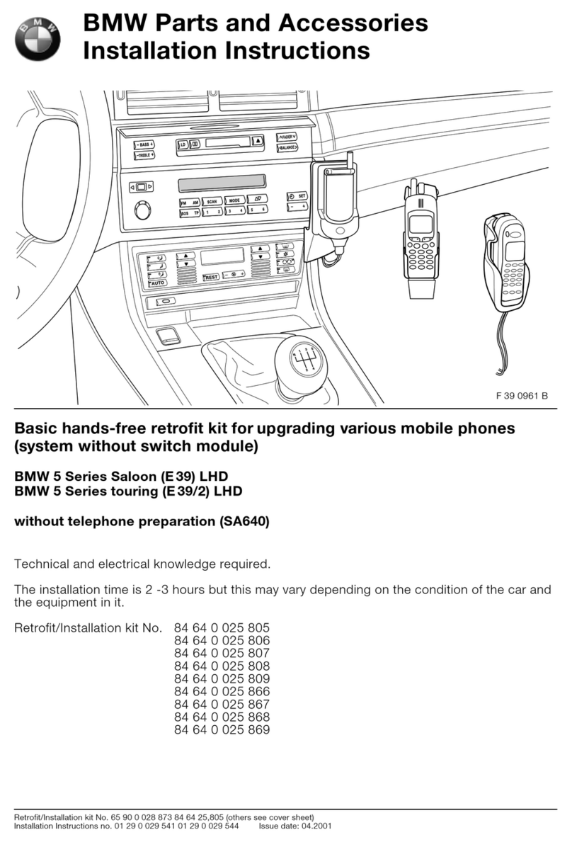
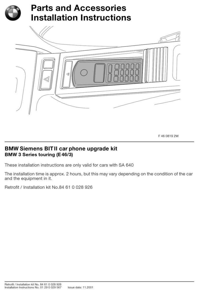
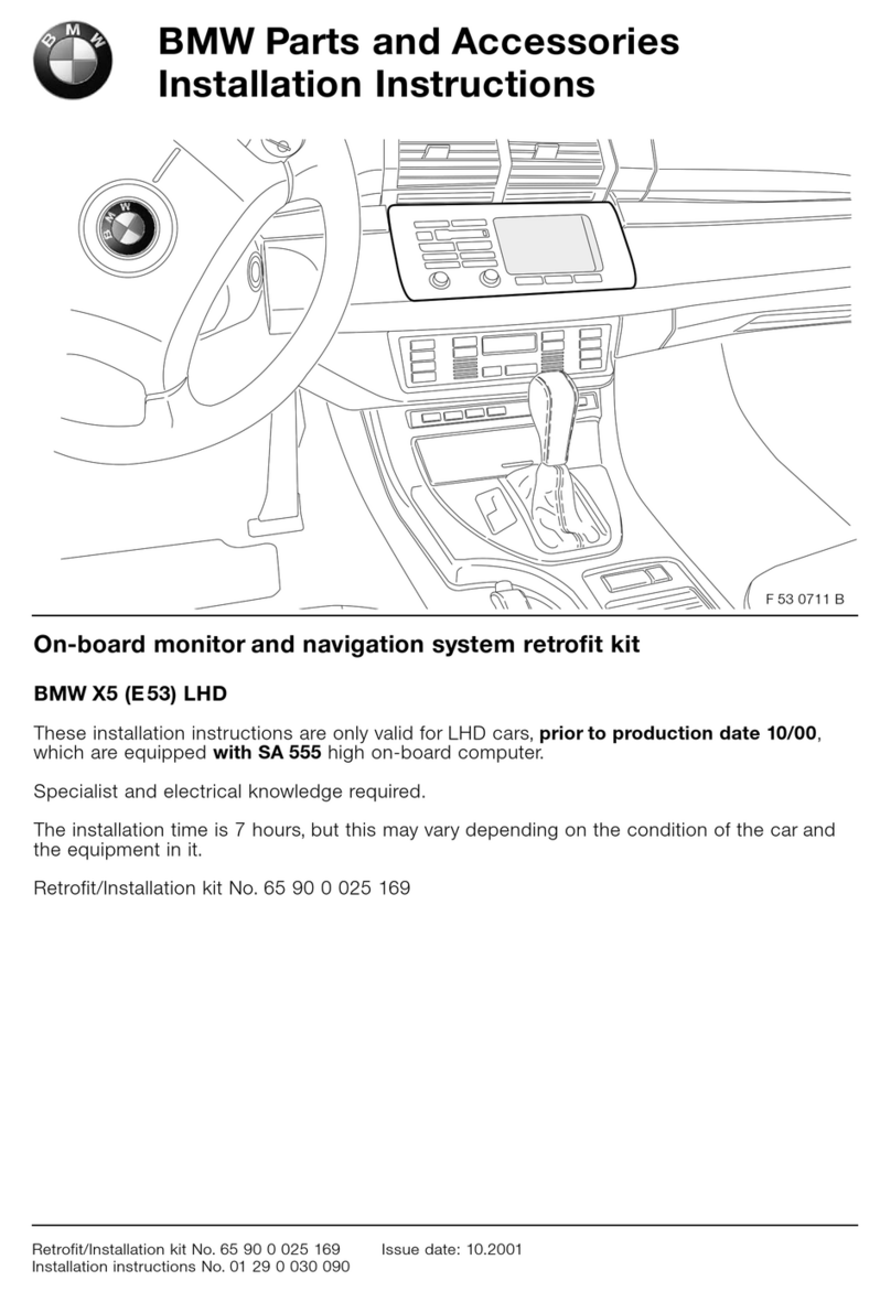
BMW 84 64 0 301 448 User manual

Parts and Accessories
Installation Instructions
© BMW Group Installation Instructions No. 01 29 0 301 626 Issue date: 02.2003
Classic Hands-Free Device Retrofit Kit
BMW Z4 (E
85 )
Retrofit kit part number: 84 64 0 301 448
Installation time:
The installation time is 4.0 hours, but this may vary depending on the condition of the car and the
equipment in it.
Important information:
- These installation instructions are primarily intended for use in the BMW dealer organisation and
by authorised BMW dealerships;
Irrespective of where these installation instructions are used, their target group is specialist
personnel trained on BMW cars with the appropriate specialist knowledge.
- All work must be completed using the latest repair manuals, circuit diagrams, servicing manuals
and work instructions in a rational order using the prescribed tools (special tools) and observing
current health and safety regulations.
- Ensure that the cables/lines are not kinked or damaged as you install them in the car.
- If the specified PIN numbers are occupied, bridges, double crimps or twin-lead terminals must
be used.
- All the figures show LHD cars, proceed accordingly on RHD cars.
- Item numbers refer only to the overview drawing and to the texts next to the appropriate figure.
- Subject to technical modifications.
- See the EBA CD or ASAP (Aftersales Assistance Portal) for explanations of the pictograms.
- Do not print out these installation instructions, since daily updates are available via ASAP!
Special tools:
None

EN/2© BMW Group Installation Instructions No. 01 29 0 301 626 Issue date: 02.2003
Contents
Section Page
Important information . . . . . . . . . . . . . . . . . . . . . . . . . . . . . . . . . . . . . . . . . . . . . . . . . . . . . . . . . . . . . .1
1. Parts list . . . . . . . . . . . . . . . . . . . . . . . . . . . . . . . . . . . . . . . . . . . . . . . . . . . . . . . . . . . . . . . . . . . . . . . . . 3
2. Preparations. . . . . . . . . . . . . . . . . . . . . . . . . . . . . . . . . . . . . . . . . . . . . . . . . . . . . . . . . . . . . . . . . . . . . . 4
3. Connection overview . . . . . . . . . . . . . . . . . . . . . . . . . . . . . . . . . . . . . . . . . . . . . . . . . . . . . . . . . . . . . . 5
4. Installation and cabling diagram . . . . . . . . . . . . . . . . . . . . . . . . . . . . . . . . . . . . . . . . . . . . . . . . . . . . 7
5. To cut the centre console. . . . . . . . . . . . . . . . . . . . . . . . . . . . . . . . . . . . . . . . . . . . . . . . . . . . . . . . . . 8
6. To install the wiring harness . . . . . . . . . . . . . . . . . . . . . . . . . . . . . . . . . . . . . . . . . . . . . . . . . . . . . . 10
7. To install the eject box . . . . . . . . . . . . . . . . . . . . . . . . . . . . . . . . . . . . . . . . . . . . . . . . . . . . . . . . . . . 13
8. Coding. . . . . . . . . . . . . . . . . . . . . . . . . . . . . . . . . . . . . . . . . . . . . . . . . . . . . . . . . . . . . . . . . . . . . . . . . . 16
9. Concluding work . . . . . . . . . . . . . . . . . . . . . . . . . . . . . . . . . . . . . . . . . . . . . . . . . . . . . . . . . . . . . . . . 17

EN/3© BMW Group Installation Instructions No. 01 29 0 301 626 Issue date: 02.2003
1. Parts list
1x 1x
1x
1x
1x 2x 2x
1x
1x
085 0136 B
ABC
D
H
KLM
NO
IJ
EF G
1x 1x 4x
1x 1x
1x
5 A

EN/4© BMW Group Installation Instructions No. 01 29 0 301 626 Issue date: 02.2003
2. Preparations
TIS No.
Read out the error memory
Disconnect the battery
Remove the cover behind the roll bar on the left 51 43 ...
Remove the side trim top part at rear left 51 43 010
Remove the cover on the trim for the rear storage box 51 16 ...
Remove the centre console
Remove the flap from the rear storage box 51 16 239
Remove the trim for the rear storage box 51 16 235
Remove the glove compartment
Remove the A pillar trim on the right
Remove the interior light

EN/5© BMW Group Installation Instructions No. 01 29 0 301 626 Issue date: 02.2003
3. Connection overview
Telephone adapter cable A
Item Description Signals Cable colour Connection location in the car Abbreviation
/Slot
A Telephone adapter cable
A1 White 12-pin socket casing Behind driver's seat trim to white 12-pin
plug casing
X322S
A2 White 12-pin plug casing Behind driver's seat trim to white 12-pin
socket casing
X322B
A3 Fakra socket casing To branch C1 of aerial cable extension C
A4 Black 54-pin socket casing Black 54-pin adapter plug D
A5 Cable eyelet, 6 mm diameter To earth post connection in front of rear
left MacPherson strut tower
X13016
A6 Black 3-pin socket casing Compensator connection plug
(must be tied back)
X1765B
A7 Black 3-pin plug casing To branch B1 of microphone cable
extension B
A8 Black 12-pin socket casing In radio connection plug (if the plug in the
car is already occupied, all cables must be
reconnected in the same way)
X13598
A9 Socket contact Mute WS/BR To 16-pin radio connection plug PIN 10 X18126/10
A10 Socket contact TeleON WS/GN To 16-pin radio connection plug PIN 11 X18126/11
A11 Fakra plug casing To Fakra socket casing of
eject box K
A12 Black 18-pin socket casing To black 18-pin plug casing of
eject box K
085 0137 B
A11 A12
A8
D
A7
A
A6 A5
A3
C1
C
C2
A4
A2
A1
B1
B
B2
A9 A10

EN/6© BMW Group Installation Instructions No. 01 29 0 301 626 Issue date: 02.2003
3. Connection overview
Microphone cable extension B
Aerial cable extension C
Item Description Signals Cable colour Connection location in the car Abbreviation
/Slot
B Microphone cable extension
B1 Black 3-pin socket casing To branch A7 of telephone adapter cable A
B2 Black 3-pin socket casing To microphone E
Item Description Signals Cable colour Connection location in the car Abbreviation
/Slot
C Aerial cable extension
C1 Fakra socket casing To branch A3 of telephone adapter cable A
C2 Fakra socket casing To connection provided in amplifier of
rubber aerial
085 0137 B
A11 A12
A8
D
A7
A
A6 A5
A3
C1
C
C2
A4
A2
A1
B1
B
B2
A9 A10

EN/7© BMW Group Installation Instructions No. 01 29 0 301 626 Issue date: 02.2003
4. Installation and cabling diagram
All the wiring harnesses are to be laid as shown in the figure and secured with cable ties.
Tie back any excess lengths.
Telephone adapter cable A
Microphone cable extension B
Aerial cable extension C
A1 To X322S
A2 To X322B
A3 To branch C1
A4 To D
A5 To X13016
A6 Tie back
A7 To branch B1
A8 In radio connection plug
A9 In radio connection plug
A10 In radio connection plug
A11 To eject box K
A12 To eject box K
B1 To branch A7
B2 To microphone E
C1 To branch A3
C2 To aerial amplifier
085 0138 B
A11
A12
A2
B2
A10
A9
B1
B
A
A7
A8
C2
A3 C1
A1 A4
A5
A6
C
D

EN/8© BMW Group Installation Instructions No. 01 29 0 301 626 Issue date: 02.2003
5. To cut the centre console
Undo the screws on the console cover 1.
Remove the console cover 1from the centre
console 2.
Place template Non the centre console 1and
line it up with the grooves 2on the right and
left as well as with the rear step 3.
Stick template Nonto the centre console.
Make a cut-out 1around the grey shape.
Transfer the cut line 1with dimension aonto
the console cover 2and cut across as shown
in the figure.
Dimension a= 185 mm
085 0198 B
1
2
&# '' *
1
1
N
2
2
2
23
3
085 0200 B
1
&# *
=

EN/9© BMW Group Installation Instructions No. 01 29 0 301 626 Issue date: 02.2003
5. To cut the centre console
Use screws to attach the cut console cover 1
to the centre console 2.
085 0202 B
1
2

EN/10© BMW Group Installation Instructions No. 01 29 0 301 626 Issue date: 02.2003
6. To install the wiring harness
Separate white 12-pin plug connector X322.
Connect branch A1 to white 12-pin plug
casing X322S.
Connect branch A2 to white 12-pin socket
casing X322B.
Route branch A11/A12 as illustrated.
Route branch A3-A6 into the boot.
Route branch A7-A10 as illustrated.
Route branch A8-A10 to the radio connection
plug 1.
:! *
:! 5
)
)
&# *
085 0213 B
A3-A6
A11
A1 2
A
085 0214 B
A9
A7
A1 0
A8
&# % *
)
)&
)'

EN/11© BMW Group Installation Instructions No. 01 29 0 301 626 Issue date: 02.2003
6. To install the wiring harness
Connect branch A9 to radio connection plug
X18126, PIN 10.
Connect branch A10 to radio connection plug
X18126, PIN 11.
Connect branch A8, X13598 to radio
connection plug X18126.
If the plug in the car is already occupied,
all cables must be reconnected in the
same way.
Connect branch A7 to branch B1.
Route branch B2 to the installation site of the
hands-free microphone.
Clip hands-free microphone Einto the ceiling
light 1.
The arrow on hands-free microphone E
must point to the front of the car.
Connect branch B2 to hands-free microphone
E.
&# & *
)
)'
:& $
&# ' *
)&
:& $
B2
B1
A7
085 0205 B
E
1
B2
085 0138 B

EN/12© BMW Group Installation Instructions No. 01 29 0 301 626 Issue date: 02.2003
6. To install the wiring harness
Connect branch A5 to earth post connection
X13016.
Tie branch A6 back to the wiring harness.
Connect branch A4 to adapter plug Dand
wrap rattle guard Laround it.
Connect branch A3 to branch C1.
Route branch C2 as illustrated to the
installation site of the rubber aerial 1.
Connect branch C2 to the slot provided in the
aerial amplifier 1.
&# ! *
)#
)$
:!$
&# " *
D
A4
L
085 0210 B
C1 C2
A3
1
085 0211 B
1
C2

EN/13© BMW Group Installation Instructions No. 01 29 0 301 626 Issue date: 02.2003
7. To install the eject box
Place the cut centre console 1into the car.
Route branch A11/A12 through the centre
console 1.
Attach the centre console 1.
Place console cover Fonto the centre console
1and line it up.
Transfer the holes 2onto the centre console
1.
Drill the hole with a 1.5 mm drill bit.
Undo the centre console 1.
Connect branch A11/A12 to eject box K.
Pull back telephone adapter cable Aat the
provided point 2and tie it back.
085 0217 B
1
085 0218 B
A11
A12
1
&# ' *
.
085 0215 B
K
A11
A12
2
1
A

EN/14© BMW Group Installation Instructions No. 01 29 0 301 626 Issue date: 02.2003
7. To install the eject box
Attach the centre console 1.
Attach console cover Fusing screws G.
Insert the front of eject box Kinto the console
cover 1and clip it in at the back.
Remove the cable tie 1from the bellows 2.
Remove the handbrake grip 3.
Use cable tie Mto attach the handbrake grip 1
to bellows H.
085 0216 B
F
1
G G
085 0222 B
1
K
085 0223 B
1
2
3
085 0224 B
1
M
H

EN/15© BMW Group Installation Instructions No. 01 29 0 301 626 Issue date: 02.2003
7. To install the eject box
Stick Velcro strip Ito armrest Jand glue into
console cover F.
Attach bellows Hto the centre console 1.
085 0226 B
J
F
I
085 0225 B
H
1

EN/16© BMW Group Installation Instructions No. 01 29 0 301 626 Issue date: 02.2003
8. Coding
This system is not diagnostics-capable and does not have to be coded.

EN/17© BMW Group Installation Instructions No. 01 29 0 301 626 Issue date: 02.2003
9. Concluding work
Connect battery
Conduct a function test on the hands-free device.
Assemble the car following the instructions to dismantle it in reverse order
Print out error memory
Table of contents
Other BMW Automobile Accessories manuals

BMW
BMW 1 Series User manual

BMW
BMW 84 61 0 143 953 User manual

BMW
BMW i Wallbox Connect User manual

BMW
BMW S84 03 U86 User manual

BMW
BMW FXX ATM Emulator Operating manual

BMW
BMW Komfort User manual

BMW
BMW 82 44 0 007 417 User manual

BMW
BMW E39 User manual

BMW
BMW B84 02 03 User manual

BMW
BMW Advanced Car Eye User manual

BMW
BMW 84 64 0 398 228 User manual

BMW
BMW R50 User manual

BMW
BMW 325i 1991 Programming manual

BMW
BMW 84 64 0 441 949 User manual

BMW
BMW 84 64 0 153 493 User manual

BMW
BMW X5 (E53) LHD User manual

BMW
BMW 01290015988 User manual

BMW
BMW SA655 User manual

BMW
BMW 84 64 0 302 016 User manual

BMW
BMW 65 12 0 137 916 User manual