BMW 66 20 0 146 507 User manual

Original BMW Accessories.
Installation Instructions.
© BMW AG, Munich 01 290 149 181 11/2008 (T/S) 1
Retrofit Park Distance Control (PDC), front and rear
BMW 7 Series (E
65) LHD
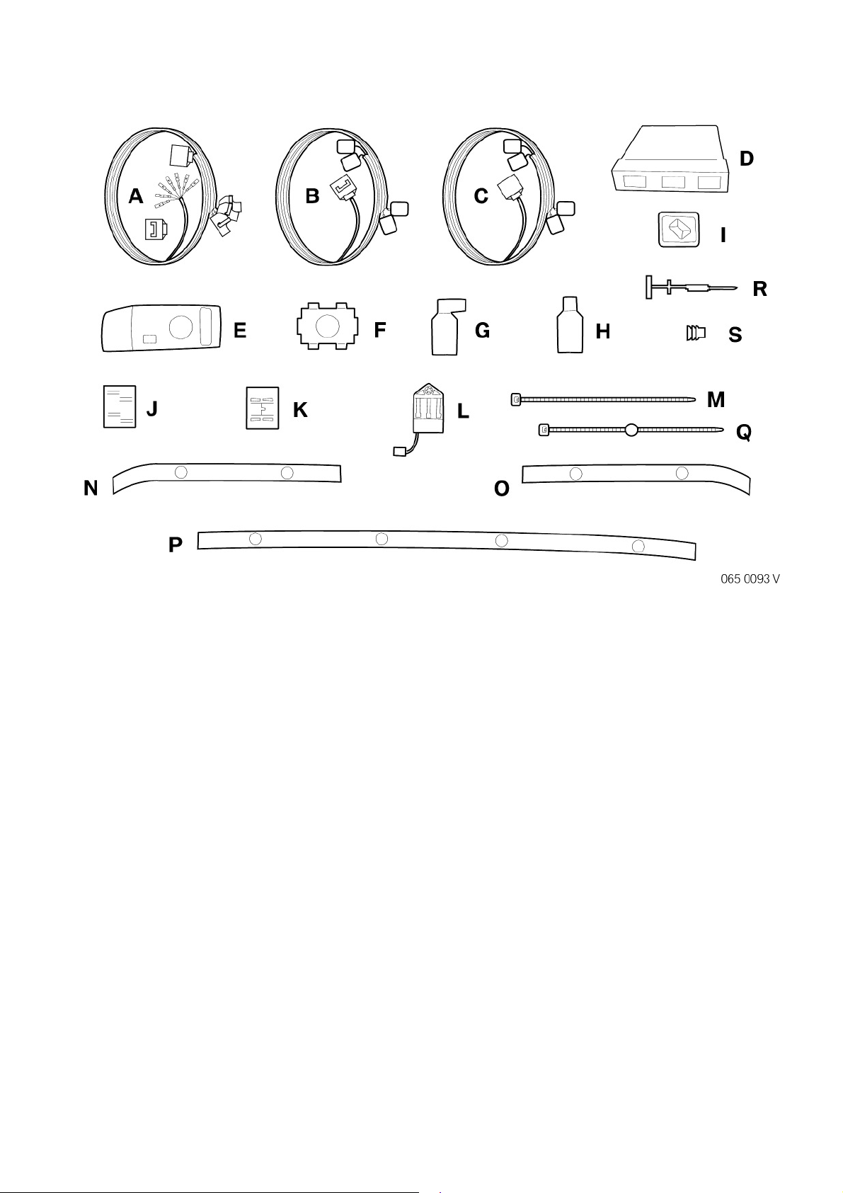
Retrofit kit No. 66 20 0 146 507 Retrofit kit Park Distance Control
Installation time
The installation time of approx. 6.0 hours may vary dependin on the vehicle's condition and
equipment.
The installation time iven does not include time needed for pro rammin /encodin .
The total costs for the pro rammin time should be taken into account when calculatin retrofittin
costs (reimbursement throu h warranty is not permissible).
Important information
These installation instructions are primarily desi ned for use within the BMW dealership or anisation
and by authorised BMW service companies.
In any event, the tar et roup for these installation instructions is specialist personnel trained on BMW
cars with the appropriate specialist knowled e.
All work must be completed usin the latest BMW repair manuals, circuit dia rams, servicin manuals
and work instructions, in a rational order, usin the specified tools (special tools) and observin current
health and safety re ulations.
In the event of installation or functional problems, limit troubleshooting to 0.5 hours for
mechanical jobs and 1.0 hours for electrical jobs.
To avoid unnecessary work and costs, send a correspondin enquiry via the Aftersales Assistance
Portal (ASAP) usin the technical parts support application.
Please quote the followin :
- Vehicle identification number
- Part number of retrofit kit
- Exact description of the problem
- Work already carried out.
Do not archive the hard copy of these installation instructions since daily updates are made by ASAP!
Pictograms
Denotes instructions that draw your attention to special features.
Denotes the end of the instruction or other text.

© BMW AG, Munich 01 29 0 149 181 11/2008 (T/S) 2
Installation information
All pictures show LHD cars; proceed accordin ly on RHD cars.
Ensure that the cables/lines are not kinked or dama ed as you install them in the car. Costs incurred as
a result of this will not be reimbursed by BMW AG.
Additional cables and/or lines that you install must be secured with cable ties.
If the specified PIN chambers are occupied, brid es, double crimps or twin-lead terminals must be used.
The control unit status (condition) must be checked with the test pro ram CIP (codin , individualisin ,
pro rammin ) before installin the retrofit. If the check finds incorrect or faulty statuses in one or several
control units, they must be first corrected/updated with the "Load software" function.
Special tools required
Removal aid 00 9 341
Blade 00 9 321
Release hook 64 1 030
Crimpin pliers for AMP contacts

© BMW AG, Munich 01 29 0 149 181 11/2008 (T/S) 3
Contents
Section Pa e
1. Parts overview . . . . . . . . . . . . . . . . . . . . . . . . . . . . . . . . . . . . . . . . . . . . . . . . . . . . . . . . . . . . . . . . . . . . . 4
2. Preparatory work . . . . . . . . . . . . . . . . . . . . . . . . . . . . . . . . . . . . . . . . . . . . . . . . . . . . . . . . . . . . . . . . . . . 5
3. Connections dia ram, PDC wirin loom . . . . . . . . . . . . . . . . . . . . . . . . . . . . . . . . . . . . . . . . . . . . . . . 6
4. Connections dia ram, converter wirin loom. . . . . . . . . . . . . . . . . . . . . . . . . . . . . . . . . . . . . . . . . . . 8
5. Installation and cablin dia ram . . . . . . . . . . . . . . . . . . . . . . . . . . . . . . . . . . . . . . . . . . . . . . . . . . . . . . 9
6. Installin Park Distance Control . . . . . . . . . . . . . . . . . . . . . . . . . . . . . . . . . . . . . . . . . . . . . . . . . . . . . . 10
7. Finishin off and codin . . . . . . . . . . . . . . . . . . . . . . . . . . . . . . . . . . . . . . . . . . . . . . . . . . . . . . . . . . . . . 15
8. Circuit dia ram . . . . . . . . . . . . . . . . . . . . . . . . . . . . . . . . . . . . . . . . . . . . . . . . . . . . . . . . . . . . . . . . . . . . . 16

© BMW AG, Munich 01 29 0 149 181 11/2008 (T/S) 4
1. Parts overview
Legend
APDC wirin loom (1x)
BRear converter wirin loom (1x)
CFront converter wirin loom (1x)
DPDC control unit (1x)
EControl panel with switch (1x)
F Holder for ultrasonic converter (8x)
G Ultrasonic converter, rear (4x)
HUltrasonic converter, front (4x)
IHolder (2x)
JInsulation displacement connector (1x)
KCover,insulation displacement connector (1x)
LStrip connector (3x)
MCable tie (30x)
NBumper strip, front ri ht (1x)
OBumper strip, front left (1x)
PBumper strip, rear (1x)
QCable tie for bumper panel (5x)
RPin contact (20x)
SIndividual seal (20x)

© BMW AG, Munich 01 29 0 149 181 11/2008 (T/S) 5
2. Preparatory work
ISTA No.
Perform quick test ---
Disconnect ne ative terminal of battery 12 00 ...
Remove the following components
Front bumper panel 51 11 156
Rear bumper panel 51 12 156
Microfilter, ri ht 64 31 010
Glove compartment, ri ht 51 16 367
Side trim panel on A-pillar in ri ht footwell 51 43 075
Instrument panel finisher, centre 51 45 ...
Front ri ht sill cover panel 51 47 000
Trim panel for bottom ri ht door pillar 51 43 150
Rear ri ht sill cover panel 51 47 030
Additional bottom ri ht cover on C-pillar 51 43 240
Bottom ri ht cover on C-pillar 51 43 230
Lu a e compartment floor trim panel 51 47 101
Lu a e compartment wheel arch trim panel, ri ht 51 47 161

© BMW AG, Munich 01 29 0 149 181 11/2008 (T/S) 6
3. Connections diagram, PDC wiring loom
Item Description Signal Cable colours/
cross section
Plug-in location in vehicle Designation/
plug-in location
A PDC wirin harness --- --- --- ---
A1 12-pin black socket housin
---
SWWS/GEWS/
BRWS/SWGR/
GEGR/BRGR/
SWBL/GEBL/
BRBL/SWGE/
GEGN/BRGE
At 12-pin pin housin from rear converter wirin
loom
X13698B
A2 Socket contact Earth BR/SW At 7-pin strip connector in lu a e compartment,
rear ri ht
X13075
A3 18-pin black socket housin
---
SWWS/GEWS/
BRWS/SWGR/
GEGR/BRGR/
SWBL/GEBL/
BRBL/SWGE/
GEGN/BRGE
At 18-pin black connector from PDC control unit X18362
A4 18-pin white socket housin
---
SWWS/GEWS/
BRWS/SWGR/
GEGR/BRGR/
SWBL/GEBL/
BRBL/SWGE/
GEGN/BRGE
At 18-pin white connector from PDC control unit X18013

© BMW AG, Munich 01 29 0 149 181 11/2008 (T/S) 7
3. Connections dia ram, PDC wirin loom
Item Description Signal Cable colours/
cross section
Plug-in location in vehicle Designation/
plug-in location
A5 12-pin black socket housin
---
BRBLGE/
BRGRGE/GN/
GNOR/GNBL/
BR/SW
At 12-pin black connector of PDC control unit X300
A6 Socket contact Kl. 15 GNBL At 32-pin black socket housin at power module X1856 PIN 5
A7 Ribbon cable K-CAN GNOR/GN With insulation displacement connector at
GNOR/GN ribbon cable K-CAN at
ri ht-hand A-pillar
---
A8 4-pin black socket housin
---
BRBLGE/
BRGRGE/
BRSW/GRRT
At PDC switch X361
A9 Socket contact Kl. 31 BR/SW At strip connector in footwell, driver's side X217
A10 Socket contact Kl. 58G GRRT At strip connector in footwell, driver's side X806
A11 Pin contacts
---
SWWS/GEWS/
BRWS/SWGR/
GEGR/BRGR/
SWBL/GEBL/
BRBL/SWGE/
GEGN/BRGE
In 12-pin black pin housin A12 X10647S
A12 12-pin black pin housin --- --- At 12-pin socket housin of front converter
wirin loom
X10647S

© BMW AG, Munich 01 29 0 149 181 11/2008 (T/S) 8
4. Connections diagram, converter wiring loom
Item Description Signal Cable colours/
cross section
Plug-in location in vehicle Designation/
plug-in location
B Rear converter wirin loom --- --- --- ---
B1 3-pin black socket housin --- SWWS/GEWS/
BRWS
At ultrasonic converter, rear left X18020
A2 3-pin black socket housin --- SWGR/GEGR/
BRGR
At ultrasonic converter, rear centre left X18021
B3 3-pin black socket housin --- SWBL/GEBL/
BRBL
At ultrasonic converter, rear centre ri ht X18022
B4 3-pin black socket housin --- SWGE/GEGN/
Brown/yellow
At ultrasonic converter, rear ri ht X18023
B5 12-pin black pin housin
---
SWWS/GEWS/
BRWS/SWGR/
GEGR/BRGR/
SWBL/GEBL/
BRBL/SWGE/
GEGN/BRGE
At 12-pin black socket housin of PDC wirin
loom
X13698S
C Front converter wirin loom --- --- --- ---
C1 3-pin black socket housin --- SWWS/GEWS/
BRWS
At ultrasonic converter, front left X18016
C2 3-pin black socket housin --- SWGR/GEGR/
BRGR
At ultrasonic converter, front centre left X18017
C3 3-pin black socket housin --- SWBL/GEBL/
BRBL
At ultrasonic converter, front centre ri ht X18018
C4 3-pin black socket housin --- SWGE/GEGN/
Brown/yellow
At ultrasonic converter, front ri ht X18019
C5 12-pin black socket housin
---
SWWS/GEWS/
BRWS/SWGR/
GEGR/BRGR/
SWBL/GEBL/
BRBL/SWGE/
GEGN/BRGE
At 12-pin black pin housin of PDC wirin
loom
X10647B

© BMW AG, Munich 01 29 0 149 181 11/2008 (T/S) 9
5. Installation and cabling diagram
Legend
1 Ultrasonic converter, front left
2 Ultrasonic converter, front centre left
3 Ultrasonic converter, front centre ri ht
4 Ultrasonic converter, front ri ht
5 K-CAN at A-pillar, ri ht
6 PDC switch
7 Strip connector in footwell, driver's side
8 Power module
9 PDC control unit
10 Ground pin
11 Ultrasonic converter, rear ri ht
12 Ultrasonic converter, rear centre ri ht
13 Ultrasonic converter, rear centre left
14 Ultrasonic converter, rear left

© BMW AG, Munich 01 29 0 149 181 11/2008 (T/S) 10
6. Installing Park Distance Control
Pull PDC wirin loom A throu h openin in body
at rear ri ht of vehicle into the lu a e compart-
ment.
Fit rommet (1) on branch A1 of PDC wirin
loom A in the openin .
The 12-pin black socket housin of
branch A1 will be connected later to the
12-pin black pin housin B5 of rear con-
verter wirin loom B.
Plu in socket contact of branch A2 at free slot in
strip connector X13075 (1) on rear ri ht in lu -
a e compartment.
If there is no free plu -in slot in strip con-
nector X13075 (1), a twin-lead terminal
must be made with strip connector L from
the parts kit (not illustrated).
Fit PDC control unit D in the compartment pro-
vided in bracket (1).
Connect and lock branch A3 at 18-pin black
connector X18362 of PDC control unit D.
Connect and lock branch A4 at 18-pin white
connector X18013 of PDC control unit D.
Connect and lock branch A5 at 12-pin black
connector X300 of PDC control unit D.

© BMW AG, Munich 01 29 0 149 181 11/2008 (T/S) 11
6. Installin Park Distance Control
-
Unplu 32-pin black socket housin X1856 (1) at
power module (2) and disassemble.
Plu in socket contact of branch A6 at PIN 5 of
socket housin X1856 (1).
Reassemble socket housin X1856 (1).
Connect and lock at power module (2).
Pass wirin loom A throu h rommet (1) from
lu a e compartment into vehicle interior.
Route wirin loom A alon main wirin har-
ness (2) on ri ht-hand side of vehicle to front
ri ht A-pillar.
Secure wirin loom A with cable ties M to main
wirin harness (2).
-
Make twin-lead terminal with branch A7 at ribbon
cable (colour GNOR/GN) (1) at ri ht-hand A-
pillar.
For this purpose, place both ribbon cables in the
correct position in insulation displacement con-
nector J and close off with cover to insulation dis-
placement connector K.
Make sure the cover to insulation displace-
ment connector K is fitted securely.
The retainin lu s must snap into insula-
tion displacement connector J.
Tie back excess len ths.
In the area of the instrument carrier, route
branches A8, A9 and A10 of PDC wirin loom A
to the left behind the love compartment.
Secure PDC wirin loom A with cable ties to the
existin wirin harness (1).

© BMW AG, Munich 01 29 0 149 181 11/2008 (T/S) 12
6. Installin Park Distance Control
-
In centre area of dashboard, route branches A8,
A9 and A10 of PDC wirin loom A further to the
left.
Secure PDC wirin loom A with cable ties to the
existin wirin harness (1).
Route 4-pin black socket housin X361 of
branch A8 to location of PDC switch.
Route branches A9 and A10 behind knee uard
into footwell on driver's side.
Connect 4-pin black socket housin X361 to
PDC switch and install control panel E with
PDC switch (not illustrated) as described in
TIS instructions 51 45 ... .
-
Connect socket contacts of branches A9 and
A10 at strip connector (1) in footwell on driver's
side as follows:
Socket contact of branch A9 in strip connector
X217 with BRSW wire.
Socket contact of branch A10 in strip connector
X806 with GRRT wire.
If there are no free plu -in slots in strip con-
nectors X217 and X806 twin-lead termi-
nals must be made with strip connector L
from the parts kit (not illustrated ).
Route branch A11 in ri ht-hand A-pillar up to
rommet (1).
Pass branch A11 throu h rommet (1) into
en ine compartment.

© BMW AG, Munich 01 29 0 149 181 11/2008 (T/S) 13
6. Installin Park Distance Control
-
Make an openin in the rommet (1) in front of
the control unit box, pass branch A11 throu h
the rommet (1) and run further forward.
Use suitable sealin compound to seal off
openin in rommet (1).
Connect the 12 wires of branch A11 as follows:
- Fit individual seals R on wires (1)
- Fit wires (1) and individual seals R in pin con-
tacts S and crimp on with crimpin pliers for
AMP contacts.
Confi ure 12-pin pin housin A12 as follows:
Plu in SWWS wire at PIN 1
Plu in GEWS wire at PIN 2
Plu in BRWS wire at PIN 3
Plu in SWGR wire at PIN 4
Plu in GEGR wire at PIN 5
Plu in BRGR wire at PIN 6
Plu in SWBL wire at PIN 7
Plu in GEBL wire at PIN 8
Plu in BRBL wire at PIN 9
Plu in SWGE wire at PIN 10
Plu in GEGN wire at PIN 11
Plu in BRGE wire at PIN 12
Ensure correct codin of the pin con-
tacts R. Check for firm fit.
The pin contacts R can only be unplu ed
a ain with a special tool that is not always
available in the BMW dealership or anisa-
tion.
After plu in pin contacts R into 12-pin pin
housin A12, the pink latches (2) of 12-pin pin
housin A12 must be carefully slid towards the
middle.
The parts kit contains 20 pin contacts R
and individual seals S.
12 of each are required and 8 are provided as
spares.

© BMW AG, Munich 01 29 0 149 181 11/2008 (T/S) 14
6. Installin Park Distance Control
-
Secure front converter wirin loom Cwith cable
ties to existin wirin harness (to aluminium
section of front bumper carrier) (not illustrated).
The front converter wirin loom C is a com-
plete module.
Tie back unused branches (connections for
fo li ht, horn etc.).
Route 12-pin black socket housin C5 of front
converter wirin loom C and 12-pin black pin
housin A12 to holder mount (1) in front of the
sprin strut.
Fit holder I in the uide of pin housin A12.
Connect socket housin C5 and pin housin A12
and fit holder I in mount (1).
Fit four holders for ultrasonic converters F
and front ultrasonic converters H in front ri ht
bumper strip N and front left bumper strip O
as described in TIS instructions 66 20 520
(not illustrated).
Fit a total of five cable ties for bumper panel Q in
the holes in the rear bumper panel (1).
Install rear converter wirin loom B in rear
bumper panel (1) as described in TIS instruc-
tions 51 12 157 (not illustrated).
Install holder I as shown in illustration
065 0082 V and secure plu connection at
the correspondin openin in rear bumper
panel (1) (not illustrated).
Fit four holders for ultrasonic converters F and
rear ultrasonic converters G in rear bumper
strip P accordin to TIS instructions 66 20 540
(not illustrated).

© BMW AG, Munich 01 29 0 149 181 11/2008 (T/S) 15
7. Finishing off and coding
The retrofit system requires encodin .
- Reconnect vehicle battery
- Pro ram/encode retrofit with DISPlus, MoDIC III or GT-1 with CIP application and follow the user
prompt
- Perform quick test
- Perform function test
- Reassemble vehicle in reverse order of removal

© BMW AG, Munich 01 29 0 149 181 11/2008 (T/S) 16
8. Circuit diagram

© BMW AG, Munich 01 29 0 149 181 11/2008 (T/S) 17
8. Circuit dia ram
Legend
Cable colours
A71 Power module
A81 PDC control unit
S111 PDC switch
X217 Strip connector in footwell, driver's side
X300 12-pin black socket housin at PDC control unit
X361 4-pin black socket housin at PDC switch
X806 Strip connector in footwell, driver's side
X1856 32-pin black socket housin at power module
X10584 K-CAN connector at A-pillar, passen er's footwell
X10585 K-CAN connector at A-pillar, passen er's footwell
X10647 12-pin plu connector for PDC converter, front
X13075 Rin cable lu at strip connector in lu a e compartment
X13698 12-pin plu connector for PDC converter, rear
X18013 18-pin white socket housin at PDC control unit
X18016 3-pin black socket housin at PDC converter, front left
X18017 3-pin black socket housin at PDC converter, front centre left
X18018 3-pin black socket housin at PDC converter, front centre ri ht
X18019 3-pin black socket housin at PDC converter, front ri ht
X18020 3-pin black socket housin at PDC converter, rear left
X18021 3-pin black socket housin at PDC converter, rear centre left
X18022 3-pin black socket housin at PDC converter, rear centre ri ht
X18023 3-pin black socket housin at PDC converter, rear ri ht
X18362 18-pin black socket housin at PDC control unit
GR Grey
GE Yellow
RT Red
OR Oran e
WS White
GN Green
BR Brown
SW Black
BL Blue
Table of contents
Other BMW Automobile Electronic manuals

BMW
BMW TV VIDEO MODULE User manual

BMW
BMW Apollo 84 61 0 143 955 User manual

BMW
BMW Bluetooth Upgrade Module User manual

BMW
BMW ONBOARD COMPUTER User manual

BMW
BMW 66 20 0 007 031 User manual

BMW
BMW ONBOARD COMPUTER User manual

BMW
BMW ON-BOARD MONITOR AND NAVIGATION SYSTEMS FOR E38 E39 E46... User manual

BMW
BMW Apollo 84620029299 User manual
Popular Automobile Electronic manuals by other brands

Rydeen
Rydeen PSR4000 owner's manual

GMC
GMC AUX-GM3X Quick start installation guide

Volvo
Volvo 31399562 installation instructions

Jacob Jensen
Jacob Jensen Electronic Parking Disc 3 user manual

Audiovox
Audiovox Pursuit PT100 Owners and installation manual

JVC
JVC KD-AVX77 - EXAD - DVD Player Installation & connection manual