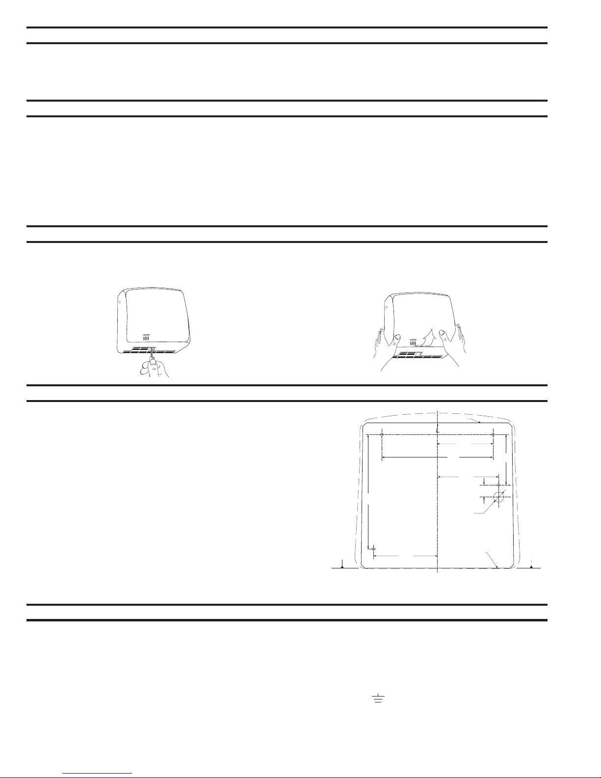
4-11/32''
(110mm)
7/8''
(22mm)
Mounting Base
Ø3/4''
(Ø18mm)
Entry Hole for
Between-Wall Wiring
C
Horizontal
Reference
5/8''
(16.5mm)
Entry Point for
Surface Mounted Wiring
3-17/32''
(90mm)
3-15/16''
(100mm)
7-7/8''
(200mm)
8-1/16''
(205mm)
4-17/32''
(115mm)
Horizontal
Reference
WARNING: TURN ELECTRICAL POWER SUPPLY OFF BEFORE MAKING
ELECTRICAL CONNECTIONS. DRYER MUST BE GROUNDED (EARTHED).
Electrical Characteristics
Recommended Mounting Heights
Removal of Cover
Installation of Mounting Base
Electrical Connection
Page 2
Model B-715,115V AC, 15 Amp, 1725 Watts, 60 HZ, SinglePhase, UL/c-UL listed.
Model B-715E, 220-240V, 7A, AC 1500-1700 Watts, 50/60 Hz, SinglePhase; VDE approved and with CE marking.
B-715E is not available in the United States and Canada.
Installationinstructions and templateprovide informationthat will assist in theinstallationof theBobrick B-715 115V, B-715E 220-240V.Retain
InstallationInstructionSheet forimportant maintenanceinstructions and warranty information.
Distancefromfloorto bottommounting screw holes of mounting base.
Men's Washrooms .................................................................................................................................................................... 46'' (1170mm)
Women's Washrooms .............................................................................................................................................................. 44'' (1120mm)
Children's Washrooms, ages 3-9 ........................................................................................................................................... 32'' (815mm)
Children's Washrooms, ages 9-12 .......................................................................................................................................... 36'' (915mm)
Children's Washrooms, ages 12-15 ........................................................................................................................................ 40'' (1015mm)
Children's Washrooms, ages 15-18 ........................................................................................................................................ 44'' (1120mm)
Barrier-Free Design ................................................................................................................................................................. 38'' (965mm)
1.Start installationof dryer by removing cover. Removethree screws, one fromeach side and one fromthebottomof thedryer. Lift thecover
fromthemounting base.
1.HoldtheInstallationTemplateagainst thewall in thedesired locationof the
installed dryer, see recommended mounting heightsabove.
2. Makesure line ontemplaterepresenting bottomof dryer mounting base is
horizontal and located at thedesired height abovefloor.
3. Mark center of fourmounting screw holes and holeforentry of electrical wiring if
electrical supply is concealed in wall and will enter dryer fromback through
mounting base.
NOTE: Surface-mounted electrical supply entry is located in the lower right corner
of the mounting base. Bottom of mounting base has 1/2'' square (13mm) opening
in lower right corner to accommodate connection of electrical conduit.
4.Drill fourholes for#10 (M4.8) mounting boltsorscrews (not furnished).
5.Formasonry wallsprovide four#10 expansionshields oranchors and secure
with four#10 (M4.8) sheet-metal screws (not furnished).Forplaster ordry wall
construction, provide concealed backing to comply with local building codes and
secure with four#10 (M4.8) round-head sheet-metal screws, or3/16'' (5mm)
togglebolts(not furnished).
NOTE: Use 2'' (50mm) long screws in top two mounting holes. Use 3'' (75mm) long
screws in lower two mounting holes.
6.Fasten mounting base securely to wall.
FOR PROPER ELECTRICAL CONNECTIONS, CHECK LOCAL BUILDING CODE. UNIT MUST BE INSTALLED BY A QUALIFIED LICENSED
ELECTRICIAN. WARNING:TURN ELECTRICAL POWER SUPPLY OFF BEFORE MAKING ELECTRICAL CONNECTIONS.
1.Connect dryer to nearest distributionpanel.Use wire as required by local electrical code. IntheUnited States and Canada use #12 wire.
2.Wiring Instructions:
a) Trim insulationfromend of electrical wire.
b) Removescrews in strain relief clamp.Removeclamping crossbar. Feed electrical wire through clamp.
c) Makeconnectionto terminal block as follows:
1) 115V Connect ground (earthed) wire to ground (earthed) terminal marked . 220-240V Dryers are doubled insulated and
shouldnot befitted with an earth (ground) wire.
2) Connect theblack or
Hot
wire to terminal marked
L1
.
3) Connect thewhiteorneutral wire to terminal marked
N
.
d) Replacecrossbar onstrain relief clamp.Tighten screws securing electrical wire.
NOTE: DEDICATED LINE IS REQUIRED FOR EACH 115 VOLT DRYER.
*Bobrick automatic hand dryers shouldbeinstalled 15" (380mm) aboveany projectionorhorizontal surfacewhich may interfere with the
operationof theautomatic sensor.


