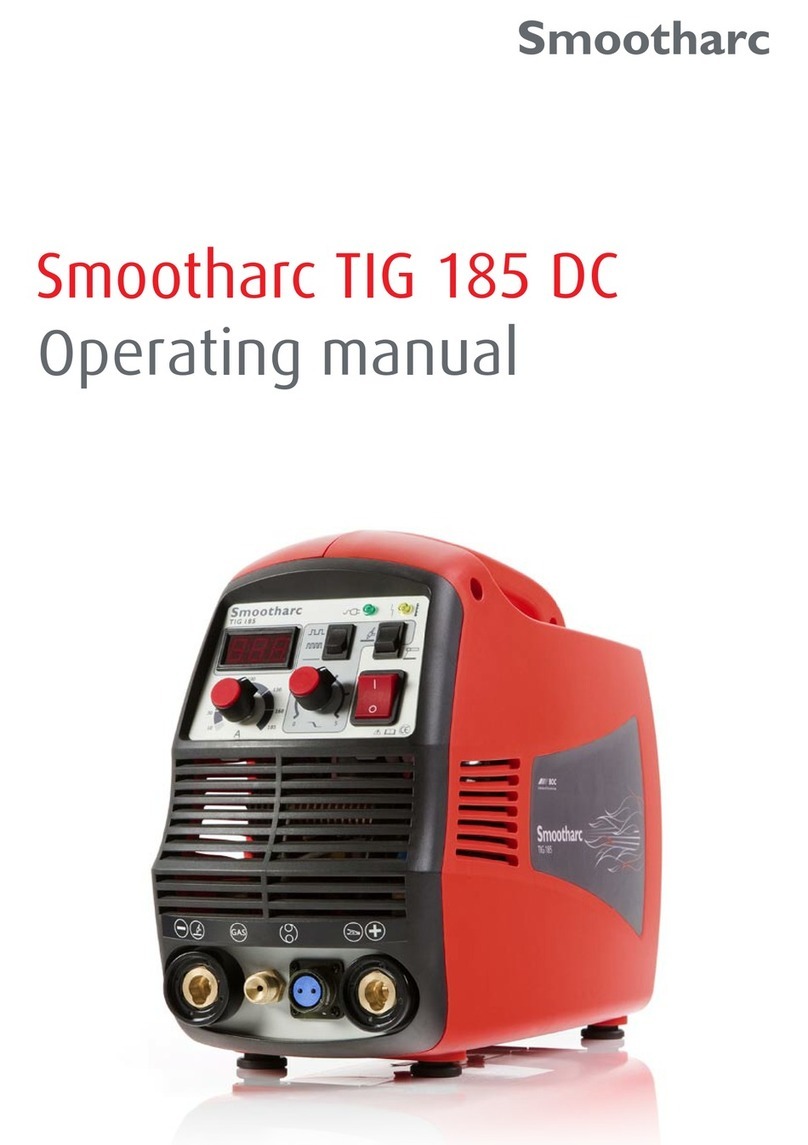
BOC Smootharc TIG 185 DC User manual

TIG 185 DC
Service manual

Ver.1 Rev.1 . 0314
•
Important Notice
ThisdocumenthasbeenpreparedbyBOCLimitedABN95000029729(‘BOC’),
asgeneralinformationanddoesnotcontainandisnottobetakenascontaining
anyspecicrecommendation.Thedocumenthasbeenpreparedingoodfaith
andisprofessionalopiniononly.Informationinthisdocumenthasbeenderived
fromthirdparties,andthoughBOCbelievesittobereliableasatthetimeof
printing,BOCmakesnorepresentationorwarrantyastotheaccuracy,reliability
orcompletenessofinformationinthisdocumentanddoesnotassumeany
responsibilityforupdatinganyinformationorcorrectinganyerrororomission
whichmaybecomeapparentafterthedocumenthasbeenissued.NeitherBOC
noranyofitsagentshasindependentlyveriedtheaccuracyoftheinformation
containedinthisdocument.Theinformationinthisdocumentiscommercial
incondenceandisnottobereproduced.Therecipientacknowledgesand
agreesthatitmustmakeitsownindependentinvestigationandshould
considerseekingappropriateprofessionalrecommendationinreviewingand
evaluatingtheinformation.Thisdocumentdoesnottakeintoaccountthe
particularcircumstancesoftherecipientandtherecipientshouldnotrelyon
thisdocumentinmakinganydecisions,includingbutnotlimitedtobusiness,
safetyorotheroperationsdecisions.Exceptinsofarasliabilityunderanystatute
cannotbeexcluded,BOCanditsafliates,directors,employees,contractors
andconsultantsdonotacceptanyliability(whetherarisingincontract,tortor
otherwise)foranyerrororomissioninthisdocumentorforanyresultingloss
ordamage(whetherdirect,indirect,consequentialorotherwise)sufferedby
therecipientofthisdocumentoranyotherpersonrelyingontheinformation
containedherein.TherecipientagreesthatitshallnotseektosueorholdBOC
ortheirrespectiveagentsliableinanysuchrespectfortheprovisionofthis
documentoranyotherinformation.
Warranty Information
Terms of Warranty
BOCprovidesawarrantyfortheSmootharcTIG185
DCmachinesoldagainstdefectsinmanufacture
andmaterials.
•Validfor18monthsfromdateofpurchase.
•AnauthorisedBOCServiceAgentmustcarryout
warrantyrepairs.
•Freight,packagingandinsurancecostsaretobepaidfor
bytheclaimant.
•Noadditionalexpresswarrantyisgivenunlessinwriting
signedbyanauthorisedmanagerofBOC.
•Thiswarrantyisinadditiontoanyotherlegalrightsyou
mayhave.
Limitations on warranty
Thefollowingconditionsarenotcovered:
•Noncompliancewithoperatingandmaintenance
instructionssuchasconnectiontoincorrectfaulty
voltagesupplyincludingvoltagesurgesoutside
equipmentspecs,andincorrectoverloading.
•Naturalwearandtear,andaccidentaldamage.
•Transportorstoragedamage.
TheWarrantyisvoidif:
•Changesaremadetotheproductwithouttheapproval
ofthemanufacturer.
•Repairsarecarriedoutusingnon-approvedspareparts.
•Anon-authorisedagentcarriesoutrepairs.
Warranty repairs
BOCortheirAuthorisedServiceAgentmustbeinformed
ofthewarrantydefects,andtheproductreturnedwithin
thewarrantyperiod.
•Beforeanywarrantyworkisundertaken,thecustomer
mustprovideproofofpurchaseandserialnumberofthe
equipmentinordertovalidatethewarranty.
Thepartsreplacedunderthetermsofthewarranty
remainthepropertyofBOC.
Modification of the 15A primary input plug or fitment
of a lower rated primary input plug will render the
warranty null and void.
Recommended Safety Precautions
Electrical Shock
•Nevertouch‘live’electricalparts.
•Alwaysrepairorreplacewornordamagedparts.
•Disconnectpowersourcebeforeperformingany
maintenanceorservice.
•Earthallworkmaterials.
•Neverworkinmoistordampareas.
Avoid electric shock by:
•Wearingdryinsulatedboots.
•Wearingdryleathergloves.
•Workingonadryinsulatedoorwherepossible.
Ver.1 Rev.1 . 10132BOC Smootharc TIG185 DC Service manual
Ver.1 Rev.1 . 0314
Contents.
1.0 Fundamental schematic and circuit diagrams 4
1.1 General wiring diagram 4
1.2 First rectifier board schematic 5
1.3 First rectifier board circuit diagram 6
1.4 Aux. module board schematic 7
1.5 Aux. module board circuit diagram 7
1.6 U10 drive module board schematic 8
1.7 U10 drive module board circuit diagram 8
1.8 U9 control module board schematic 9
1.9 U9 control module board circuit diagram 10
1.10 U8 pulse control module schematic 11
1.11 U8 pulse control module board circuit diagram 12
1.12 Second rectifier board schematic 13
1.13 Second rectifier board circuit diagram 13
1.14 Filtering, high frequency board circuit diagram 14
2.0 Troubleshooting and maintenance 16
3.0 Exploded view and component parts list 17
3.1 Exploded view 17
3.2 Component parts list for Smootharc TIG 185 DC 18
Ver.1 Rev.1 . 1013 3BOC Smootharc TIG185 DC Service manual
Ver.1 Rev.1 . 03144BOC Smootharc TIG185 DC Service manual
1.1 General wiring diagram
1.0 Fundamentalschematicandcircuitdiagrams

Ver.1 Rev.1 . 0314
1.2 First rectifier board schematic
Ser. No. Pin Description
CON1 1 Undergasdelay,theoutputis24VwhenTIG
works
2 Controlworksthesignal,outputthehigh
frequencywhenTIG
3GND
4 DC24V
CON2 1 Pin1andPin2isshortfrequencywhenTIG
workscircuit,outputhigh
2
CON3 1 2T°XHighfrequency12V°A4T---Lowfrequency0V
2 DC12V
CON4 1 ConnecttogroundbyPTC-12
2 NC
3Highfrequency
CON5 1 Pin1andPin3connecttotheTIGtorch,Pin2
andPin3connecttotheMMAtorch
2
3
4 NC
CON6 1 GND
2 Theratedvoltageisadjustable
3Providepowersupplytothepotentiometer
CON7 1 GND
2 Currentfeedback
3Voltagefeedback
CON8 1 Connecttotheattenuationpotentiometer
2
3WhenconnecttoPin4,Itislowvoltage
4 GND
5 WhenconnecttoPin4,itismiddlevoltage
CON9 1 Connecttothethermalswitch,connecttothe
groundwhenover-heatworks
2 GND
Ser. No. Pin Description
CON10 1 DC24V
2 Thisportconnecttotheover-heatindicator
CON11 1 GND
2 Connecttothepowerindicator,thispinishigh
voltage
CON12 1 GND
2 GND
3DC5V
4 Thesignalterminalofthedigitalmeter
CON13 NC
CON14 1 GND
2 GND
3GND
4 NC
5 DC340V
6 DC340V
7 DC340V
CON15 1 Pin1andPin3outputACwave(+340Vand
-340V)
2 NC
3Pin1andPin3outputACwave(+340Vand
-340V)
CON16 1 InverterACoutput
2 InverterACoutput
3InverterACoutput
4 NC
5 InverterACoutput
6 InverterACoutput
7 InverterACoutput
CON17 1 Lowvoltage
2 Thesignalterminalofthedigitalmeter
3Thepowerterminalofthedigitalmeter
5BOC Smootharc TIG185 DC Service manual
Ver.1 Rev.1 . 0314
1.3 First rectifier board circuit diagram
6BOC Smootharc TIG185 DC Service manual
Ver.1 Rev.1 . 0314
Pin Description
1 ConnecttotheMOS“S”
3 DC24Vturnon/off
5 DC24VStart
7 GND
9 DC24VandShutoff
12 GND
14 OutputDC24V
1.4 Aux. module board schematic
1.5 Aux. module board circuit diagram
7BOC Smootharc TIG185 DC Service manual
Ver.1 Rev.1 . 0314
Pin Description
1 MOSoutput
2
1.6 U10 drive module board schematic
1.7 U10 drive module board circuit diagram
8BOC Smootharc TIG185 DC Service manual
Ver.1 Rev.1 . 0314
1.8 U9 control module board schematic
9BOC Smootharc TIG185 DC Service manual
Pin Description
1 DC+12V
2 GND
3 Notused
4 VoltageFeedback
5 2T/4TPresetControl
6 GivenControl
7 Notused
8 Notused
9 GND
10 GND
11 Over-currentProtectionMonitoring
12 GND
13 Over-heatProtectionMonitoring
14 GND
15 DC+24V
16 Notused
17 GND
18 SG3525ShutdownControl
19 GND
20 GND
21 DC+24V
22 GND
23 SPWMOutput
24 GND
25 SPWMOutput
26 Notused
27 SPWMOutput
28 GND
29 SPWMOutput
30 DC+24V
31 GND

Ver.1 Rev.1 . 0314
1.9 U9 control module board circuit diagram
10 BOC Smootharc TIG185 DC Service manual
Ver.1 Rev.1 . 0314
1.10 U8 pulse control module schematic
11BOC Smootharc TIG185 DC Service manual
Pin Description
1 DC+12V
2 MMA/TIGMetercontrol
3 DC+24V
4 Notused
5 GasDelayControl
6 Notused
7 (MMA)Supplyvoltageofcurrentadjustment
8 Notused
9 SG3525ShutdownControl
10 Notused
11 (TIG)Supplyvoltageofcurrentadjustment
12 Notused
13 Attenuationtimeadjustmentterminal
14 Notused
15 Frequencyswitchterminal
16 Notused
17 Frequencyswitchterminal
18 Notused
19 ControlSignal
20 Notused
21 Attenuationtimeadjustmentterminal
22 GND

Ver.1 Rev.1 . 0314
1.11 U8 pulse control module board circuit diagram
12 BOC Smootharc TIG185 DC Service manual

Ver.1 Rev.1 . 0314
1.12 Second rectifier board schematic
1.13 Second rectifier board circuit diagram
Feedback
Negative
Output
Rectifier
MMA/TIGHigh Frequency
Positive
Output
Main Transformer
Ser. No. Pin Description
CON3 1 Givencontrol
2 Voltagefeedback
3 GND
13BOC Smootharc TIG 185 DC Service manual

Ver.1 Rev.1 . 0314
1.14 Filtering, high frequency board circuit diagram
14 BOC Smootharc TIG185 DC Service manual

Ver.1 Rev.1 . 0314
Ser. No. Pin Description
CON1 1 NC
2 Fixedgasdelaytime(2.5S)whenpresstheswitchPin2is24VvoltageontheQ3is10V,Q3openK1cling,
thegasstartstoow
CON2 1 Whenpresstheswitch,thevoltageis12V;Whentheswitchisshutoff,thevoltageis0V
2 Connecttotheground
3DC+24V
CON3 switch Presstheswitch,Pin1andPin3is12V;Whentheswitchisshutoff,Pin1andPin3is0V,Pin2isNC.
K2 Delaytimestartrelay Whenthereis24Vrelayshutsoff
K1 Solenoidvalverelay WhenthevoltageQ3isover3V,Q3isopen,therelaycling,thegasows.
RX1 Resistance Aftercontinuousswitchingonandoff,theresistanceisover-heatandshutsoff,themachinecouldwork
normallyonlyaftertheresistancecoolsdownforafewminutes
K3 Highfrequencyrelay UnderTIG,presstheswitch,thereisno-loadvoltage,Q5isopen,therelayK3cling,highfrequencyinitiates,
andstartsarc.
CON4 Risevoltage,startarcby
highfrequency
UnderTIG,presstheswitch,thereisno-loadvoltage,Q5isopen,therelayK3cling,highfrequencyinitiates,
andstartsarc.
15BOC Smootharc TIG 185 DC Service manual

Ver.1 Rev.1 . 0314
2.0Troubleshootingandmaintenance
Problem Possible Reasons Solution
1 Pressthepowerswitch,
powerindicator,meter,and
fanswithnodata,pressthe
torchwithoutresponse.
1 Checkthecircuitisnormal,andexternalpowersupply(AC240)isOK.
2 Checkthepowercable,switch,andconnectoristightlyconnected,useamulti-meter
totesttheplug(PZ01-005-O1CON10)forDC340V±5V.
1 Checktheexternalpower
supply.
2 Checktheconnector.
2 Pressthepowerswitch,the
powerindicatorandmeteris
ok,thefanisabnormal,the
machinehasnoresponse
whenpressingtheswitch.
1 ChecktheinverterboardhasDC24Voutput,useamulti-metertotesttheCON4’s
PM01-001-E12pin1and2.Ifithas24Voutput,testotherareas.
2 StartrelayK1onbottomboarddoesnotrespondproperly(itcanbeindicatedbythe
solenoidvalvejumping).
3 StartrelayK2inpowercircuitdoesnotrespondproperly,checkopticalU1,MOSFET
Z24(Q4)resistorRV1,andwhethertherelayisdamagedornot.
4 Pressingthepowerbuttoncontinuouslyinashorttime,resultsintheeld-discharge
resistancebecomingoverheatedPoweroffthemachineforseveralminutes.
1 Checkandremove.
2 Checkandremove.
3 Checkandremove.
4 Turnoffthemachinefor
severalminutes.
3 Pressthepowerswitch,
powerindicator,meter,and
fanworksnormally.Pressthe
switchofthetorchwithout
response.
1 Switchofthetorchorthecableisloose.
2 Gassocketislooseorthecableisbroken.
1 Checkandremove.
2 Checkandremove.
4 Turnonthemachine
normally,withouthigh
frequency
1 Pulloffthehighfrequencycable(PM01-001-E12CON2),useamulti-metertotest
theoutputforDC230.Ifyesandcouldstartarc,checkthestartingarcunderhigh
frequency.
a) Checkwhetherthehighfrequencycableconnectiontothebottomboard
(PZ01-005-O1CON4)andcableforarcstartisnotloose.
b) Checkifthehighvoltagedischargenozzleisconnectedcorrectly,orthesurfaceis
oxidized.
c) Checkifthehighvoltagecomponents(D3-D6),highvoltageoutputcapacitors
(C7,C10,C11)arenotdamaged.
d) Checkthehighfrequencyrelayonthebottomboardisrespondingproperly.
2 CheckfortheDC230output,possiblytheinvertercircuitisabnormal.
a) Checkifthecontrolmodule,hasoutputforthedrivesignalorworksnormally.
b) Checkiftheinverterandmaincurrentcableisnotloose(PM01-001-E12CON1(.
1 Checkandreplace.
2 Checkandreplace.
5 Turnonthemachine
normally,theabnormal
indicatorison.
1 Theover-heatprotectionisactivated,turnoffthemachine,andcouldrestartthe
machinesuccessfullywhilethepowerindicatorisoff.
2 Theover-heatprotectionworks,themachinewillbeokafter2-3minutes.
3 Theinvertercircuitandstartarcisabnormal,turnoffthemachineandpulloff
theplugofthehighfrequencystartarcpowerinPM01-001-E12,thenturnonthe
machineandpresstheswitch.
a) Iftheabnormalindicatordoesnotgoon,thetransformerT1onthePZ01-005-O1
orD3-D6isdamaged.
b) Iftheabnormalindicatorison,thenpullofftheplugCON1forpowersupply
inthePM01-001-E12Ifthelightisstillon,someoftheMOSFETcomponents
aredamaged.Ifthelightgoesoff,therectierpipeonPZ01-005-O1orthe
transformerisdamaged.
c) Checkifthefeedbackcircuitisopen-circuit,checkthefeedbackcableisproperly
connected.
1 Themachinewillbeokafter
turningoffthemachinefor
veminutes.
2 Stopthemachineforawhile.
3 Checkandremove.
6 Turnonthemachine
normally,couldstartarc,but
theweldappearsblack.
1 Checkifthesolenoidvalveisjammedordamaged.
2 Thesolenoidvalverelay(PZ01-005-WK1)isdamaged.
3 Checkthetorchforwearordamage.
4 Tungstenelectrodeisinpoorcondition,ortheshieldinggasisincorrect.
1 Clean.
2 Checkandreplaceif
necessary.
3 Checkandreplaceif
necessary.
4 Replace.
7 Theweldingcurrentis
unstable,uncontrollable.
1 Thepotentiometerislooseordamaged.
2 FilteringcapacitorPZ01-005-O1inthebottomboardisleakingordamaged.
3 Theweldingcableistoolongandthinresultingintheunstablecurrent.
1 Checkandremove.
2 Checkandremove.
3 Increasethecrosssectionof
thecable.
8 Skipafterturningonthe
machine.
1 Therectiersiliconbridgeisdamaged.
2 Thepowercableisshort-circuited.
1 Checkandreplace.
2 Replace.
9 Thehighfrequencycouldnot
stop.
1 Highfrequencyrelay(PZ01-005-WK3)isdamaged.
2 Theoutputvoltagedisturbsthevoltage.
1 Checkandremove.
2 Addcapacitorbetween
outputandground.
16 BOC Smootharc TIG185 DC Service manual

3.0 Explodedviewandcomponentpartslist
3.1 Exploded view
17 BOC Smootharc TIG185 DC Service manual
Ver.1 Rev.1 . 0314

Ver.1 Rev.1 . 0314
3.2 Component parts list for Smootharc TIG 185 DC
Item Description Qty Material Part No. BOC Part No.
1 BOCrearpanelplastic 1 R-16-910220-01-A0 R-16-910220-01-A0
2 Leftcoverplastic 1 R-17-995299-02-A0 R-17-995299-02-A0
3Rightcoverplastic 1 R-17-996299-02-A0 R-17-996299-02-A0
4 BOCbottomcase 1 R-18-261880-01-A0 R-18-261880-01-A0
5 Outputboard 1 R-18-259000-01-A0 Availableonrequest
6 Uprightgirder 2 R-22-010003-01-A0 Availableonrequest
7 Uprightgirder 2 R-22-010003-02-A0 Availableonrequest
8 Rearbeamxholder 1 R-25-020101-80-A0 Availableonrequest
9 Frontcasexholder 1 R-25-020101-79-A0 Availableonrequest
10 Topsustain 1 R-25-020101-77-A0 Availableonrequest
11 LED 1 R-04-010700-19-00 04-010700-19-00
12 Toppanelinsulation 1 R-23-010100-15-A0 23-010100-15-A0
13 Bottompanelinsulation 1 R-23-010300-16-A0 Availableonrequest
14 Topwindbreakboard 1 R-23-020102-02-A0 Availableonrequest
15 Sidewindbreakboard 2 R-23-020502-04-A0 Availableonrequest
16 Gasswitchconnector 1 R-24-031200-11-A0 24-031200-11-A0
17 Fansustain( 2 R-25-020101-78-A0 Availableonrequest
18 Radiator/heatsink 1 R-26-010171-01-A0 GM-02A
19 LED 1 R-04-010700-19-01 04-010700-19-01
20 Radiator/heatsink 1 R-26-010172-01-A0 GM-02B
21 Switch 1 R-07-020000-12-00 R-07-020000-12-00
22 Frontpanel 1 R-15-030490-01-A0 R-15-030490-01-A0
23 Digitalmeter 1 R-37-110160-05-01 AB-05/37-110160-05-01
24 Cablegrommit 1 R-37-190400-07-00 R37-190400-07-00
25 Knob 2 R-37-231220-01-01 37-231220-01-01
26 35mmfemalesocket 2 R-40-160810-01-00 R-40-160810-01-00
27 Bottompanel 1 R-51-PZ01-005-W-RL Availableonrequest
28 Bottomwindbreakboard 1 R-52-GT-50-B-RL Availableonrequest
29 Siliconbridge10 1 R-52-QL-01-F-RL Availableonrequest
30 Siliconbridge13 1 R-52-QL-01-H-RL Availableonrequest
31 Aviationsocket 1 R-52-ZH-02-B-RL Availableonrequest
32 EMCboard 1 R-51-PH02-112-A R-51-PH02-112-A
33 Boatshapedswitch 1 R-07-020000-03-00 07-020000-03-00
34 Topboard 1 R-51-PM01-046-G1 PMB-46-D
35 Middleboard 1 R-51-PD01-065-A PDB-07-G
36 EMCinsulation 1 R-23-010800-52-A0 Availableonrequest
37 Mountingbracket 2 R-24-020700-48-A0 Availableonrequest
38 Boatshapedswitch 2 R-07-020000-05-00 07-020000-05-00
39 Frontcaseplastic 1 R-15-901492-02-A0 R-15-901492-02-A0
40 Solenoidvalve 1 R-37-140420-04-00 37-140420-04-00
41 Fan 1 R-37-120112-01-00 37-120112-01-00
42 Thermalswitch 1 R-06-030000-15-01 Availableonrequest
43 Spring 12 R-23-040000-63-A0 Availableonrequest
44 Absorbboard 1 R-23-050000-19-A0 23-050000-19-A0
18BOC Smootharc TIG 185 DC Service manual
MP12-0813-1.FDAUS.0314
© BOC Limited 2014. BOC is a trading name of BOC Limited, a Member of The Linde Group. Reproduction without permission is strictly prohibited. Details given in this document are
believed to be correct at the time of printing. Whilst proper care has been taken in the preparation, no liability for injury or damage resulting from its improper use can be accepted.
FormoreinformationcontacttheBOCwarrantydepartmentatwarranty@boc.com
BOC Limited
10JuliusAvenue,NorthRydeNSW2113,Australia
970–988GreatSouthRoad,Penrose,Auckland,NewZealand
BOC Customer Service Centre
Australia
131262
www.boc.com.au
NewZealand
0800111333
www.boc.co.nz
Other manuals for Smootharc TIG 185 DC
1
Table of contents
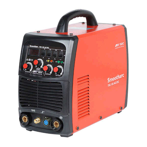
Other BOC Welding System manuals

BOC
BOC Smootharc MMA 170 User manual

BOC
BOC MIG 250C User manual

BOC
BOC C-DW User manual

BOC
BOC Firefly 130XP User manual

BOC
BOC Smootharc Elite TIG 230 AC/DC User manual

BOC
BOC Smootharc Elite MMA 162 VRD User manual

BOC
BOC Smoothcut Plasma 40 User manual

BOC
BOC Smootharc TIG185 AC/DC User manual

BOC
BOC Inverweld 110VRD User manual

BOC
BOC Smootharc Advance II User manual