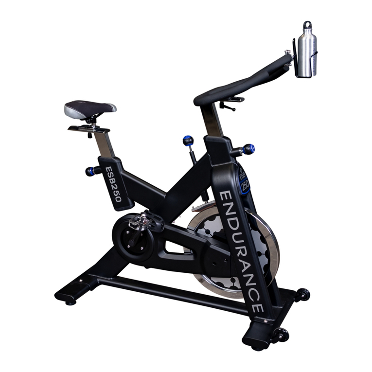
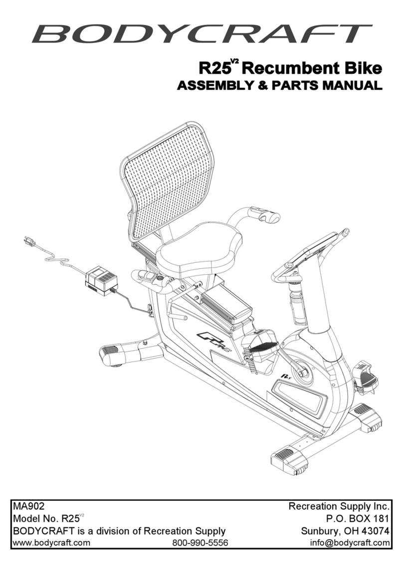
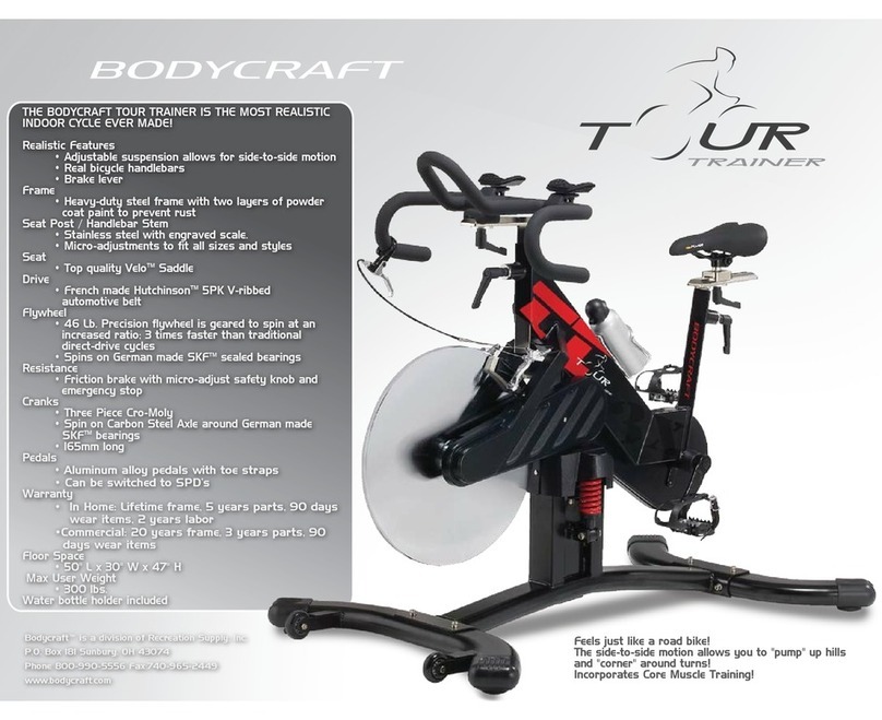
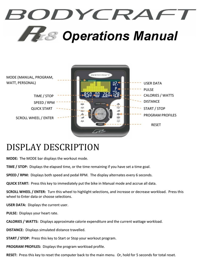
Body Craft EXP Series User manual

Owner’s Manual
1
Base Serial Number: U ____________________
Console Serial Number: ___________________
Purchased Date: ___ / ___ / ______
Dealer’s Name:__________________________
Please register your products at:
https://www.bodycraft.com/product-registration/
U1000
Upright Bike
Open your Camera
App and point it at
the QR Code
Base Serial Number
To see in
FULL COLOR
& additional information,
scan this QR code.
(U1K1-V2) ver 1.4

Congratulations and Welcome to the BODYCRAFT Family
Thank you for selecting BODYCRAFT. Your choice reflects a wise investment in you and your
facility. We hope you use it for many healthy years!
BODYCRAFT offers a complete array of high-quality fitness equipment. Please refer to our website at
www.bodycraft.com to view more ways to enhance your lifestyle.
Your BODYCRAFT machine has all the quality and design elements to make your workout extremely efficient
and comfortable. Your new unit is a serious cardio machine that will keep you motivated, challenged and
within reach of your fitness goals. Strength & cardiovascular training is vital for all ages which will provide an
effective workout, producing results that will encourage you to reach your fitness goals and maintain the
body you have always wanted.
Spending 15 to 30 minutes a day, three times a week, is all you need to start seeing the benefits of
a regular exercise program.
As a premium exercise equipment manufacturer, we are committed to your complete satisfaction. If you
have questions, suggestions or find missing or damaged parts, we guarantee your complete satisfaction
through our authorized dealer network or by contacting us directly. Please call your local dealer or
BODYCRAFT.
BODYCRAFT (a division of Recreation Supply, Inc.)
7699 Green Meadows Dr.
Lewis Center, OH 43035
Phone: 800-990-5556 9 am - 5 pm EST Email: service@bodycraft.com
Proof of purchase must be supplied to validate warranty and the product must have been
registered with BODYCRAFT via online at www.bodycraft.com or by calling 800-990-5556
or 740-965-2442 M-F 9 a.m. - 5 p.m. EST.
For parts orders, owner’s manuals, software
update files, exercise guides and contact
information scan this QR code.
Or go to:
www.bodycraft.com/customer-support

Page
Product Safety Information
FCC Information ……………………………………………………………. 4
Product Safety ……………………………………………………………. 5 - 6
Product Overview
Product Overview Components & Tools for Assembly .………………….. 7
Hardware Identification Chart ..................................................….………....8
Assembly Parts ………………………………………………………………. 9
Shipping Boxes and What’s Inside Each One ………………………… 10
How Assemble the Upright Bike
Product Assembly Instructions ..........................................…………. 11 - 13
Operation Instructions
Operating Instruction ……………………………………………………. 24
Cleaning your Bike ……..……………………………………………….. 24
Heart Rate Monitoring Grips & Wireless Receiver …………………….... 25
Erratic Heart Rate Readings & Exercise Tips ……………………………. 26
Installation Checklist …………………………………………………….. 27
Energy Saving function: These consoles are equipped with power saving function.
This means after 10 minutes of inactivity it will automatically power off. Press any
key on the console for X-9LCD or touch the screen for X-10TS/X-16TS to wake up
the console from power save mode.
3
Page
4
5 - 6
7
8
9
10
11 - 23
25 - 26
27
28
29
30
NOTE: When you have downloaded the Owner’s Manual into a PDF reader, go directly to the
desired page by touching words in this Table of Contents.
Table of Contents

Caution: Please note that changes or modifications not expressly approved by the party responsible for
compliance could void the user's authority to operate the equipment.
This device complies with Part 15 of the FCC Rules. Operation is subject to the following two conditions:
(1) This device may not cause harmful interference, and (2) this device must accept any interference
received, including interference that may cause undesired operation.
NOTE: This equipment has been tested and found to comply with the limits for a Class B digital device,
pursuant to Part 15 of the FCC Rules. These limits are designed to provide reasonable protection against
harmful interference in a residential installation. This equipment generates, uses and can radiate radio
frequency energy and, if not installed and used in accordance with the instructions, may cause harmful
interference to radio communications. However, there is no guarantee that interference will not occur in a
particular installation. If this equipment does cause harmful interference to radio or television reception,
which can be determined by turning the equipment off and on, the user is encouraged to try to correct the
interference by one or more of the following measures:
Reorient or relocate the receiving antenna.
Increase the separation between the equipment and receiver.
Connect the equipment into an outlet on a circuit different from that to which the receiver is connected.
Consult the dealer or an experienced radio/TV technician for help.
FCC CAUTION: Changes or modifications not expressly approved by the party
responsible for compliance could void the user’s authority to operate this equipment.
Page
Maintenance & Repairs
Information Needed Prior to Contacting Customer Support ……………… 28
Circuit Diagram ……………………………………………………………2... 29
Parts Lists ………..………….………………………………………….…. 30 - 31
Parts Exploded View .………………………………….…………….………. 32
Warranty
Product Warranty ..........................................................….……..….……... 33
Product Warranty Registration ............................................….…..……… 34
Contact Us Information ……………………………………………………….. 35
Table of Contents
FCC Information
Page
28
29
30 - 31
32
33
34
35
4
Page
31
32
33 - 34
35
36
37
38
Safety and Warnings - Bike
There is a risk assumed by individuals who use this type of equipment.
A moment’s lack of attention can result in an accident, as can failure to
observe certain simple safety precautions.
Read, study and understand the Assembly Instructions and all the warning labels on this
product. Furthermore, it is recommended to familiarize yourself and others with the proper
operation and workout recommendations for this BODYCRAFT product prior to use.
● We recommend that two people be available for moving and assembly of this product.
● Keep children away from the Bike. Do not allow children to use or play on the Bike.
● Keep children and pets away from the Bike when it is in use.
● It is recommended that you place this exercise equipment on an equipment mat.
● Set up and operate the Bike on a solid level surface. Do not position the Bike on loose
rugs or uneven surfaces.
● Inspect the Bike for worn or loose components prior to use.
● Tighten/replace any loose or worn components prior to using the Bike.
● Always choose the workout which best fits your physical strength and flexibility level. Know
your limits and train within them.
● Always use common sense when exercising.
● Keep hands, limbs, loose clothing and long hair well out of the way of moving parts.
● Do not wear loose or dangling clothing while using the Bike.
● Never exercise in bare feet or socks; always wear correct footwear, such as running,
walking, or cross-training shoes.
● Be careful to maintain your balance while using, mounting, dismounting, or assembling the
Bike. Loss of balance may result in a fall and serious bodily injury.
5

Safety and Warnings - Bike
● Keep both feet firmly and securely on the Foot Pedals while exercising.
● This Bike should not be used by persons weighing over 400 pounds /181 kgs.
● The Bike should be used by only one person at a time.
● Make sure that adequate space is available for access to and passage around the Bike;
keep at least a distance of 3 feet from any object while using the machine.
● This Bike is designed for commercial and home usage.
● Maintenance:
○ Replace any defective components immediately and/or keep the equipment out of use
until the equipment is completely repaired.
○ Clean seat, plastic and frame on a regular basis. We recommend warm, soapy water.
Do not use harsh or abrasive chemicals.
WARNING: Before using this product or any exercise or conditioning program, you should consult
with your personal physician to see if you require a complete physical exam. This is especially
important if you have never exercised before, are pregnant, or suffer from any illness. Follow your
physician's recommendations in developing your own personal fitness program.
READ AND FOLLOW THE SAFETY PRECAUTIONS. FAILURE TO FOLLOW THESE
INSTRUCTIONS CAN RESULT IN SERIOUS BODILY INJURY.
6

THE FOLLOWING TOOLS ARE INCLUDED FOR ASSEMBLY:
SOCKET WRENCH
(13mm)
T-HAND SOCKET
WRENCH (17mm)
PHILLIPS
SCREWDRIVER (6mm)
ALLEN WRENCH
(5 mm)
Product Overview Components and Tools for Assembly
7
EXTRA LONG PEDAL
WRENCHES 15mm (min 8” long)
THE FOLLOWING TOOLS ARE RECOMMENDED FOR EASIER ASSEMBLY:
SOCKET SET ⅜ drive w/ 3“ & 6”
EXTENSION for 13mm & 17mm
OPEN & CLOSED WRENCHES
for 13mm & 17mm
ALLEN WRENCHES SET
4mm to 10mm
PHILLIPS SCREWDRIVERS
#2 w/ Magnetic TIP
TORQUE WRENCH ⅜ DRIVE
w/ 5mm & 6mm Allen Sockets
COMBINATION
WRENCH (13mm / 15mm)
Console
Seat
HR Pulse
Sensor
Pedals
Transportation
Wheels
Levelers
Rear Stabilizer
Seat Adjustment Bar
Handlebar
Forearm Pads
Accessory
Tray
Quick-Keys

Unpack the box in a clear area. Use the List of Hardware below to check the contents of the hardware kit. This
chart is provided to help identify the hardware used in the assembly process. Place the washers, the end of bolts,
or screws on the circles to check for the correct diameter. Use the ruler to check the length of the bolts and
screws.
NOTICE: The length of all bolts and screws except those with flat heads is
measured from below the head to the end of the bolt or screw. Flat
head bolts and screws are measured from the top of the head to the
end of the bolt or screw.
Hardware Identification Chart
8
Please review below to know the content of the hardware kit.
If a part is not in the hardware bag, check to see if it has been pre-assembled.

4
Unpack the box in a clear area. Follow the List of Assembly Parts below to check and make sure all assembly parts are
present and in good condition. Do not dispose of the packing material until the assembly process is completed. Assembly
tools and hardware kit have included for you to use when assembling the product
Assembly Parts
NOTE: 9” LCD Console will NOT REQUIRES the Power Adaptor (137) & Power Cord (139) for use.
ONLY use for the 16” & 10” Touch Screen Consoles or charging the battery, if needed, for the 9” LCD
console.
9
Upright Post - Assembly
(5-ASM) Console (31)
Back Console Case
(34) Screw Cap (35) x 4 Forearm Pads (28) x 2 Adaptor (137) & Power Cord
(139)
Power Adaptor
{120AC to 12DC/3A}
Accessory Tray (37) &
Support Pad (36)
Front & Rear Tube Cover
(123, 124) Console Tube - Assembly
(33-ASM)
Handlebar - Assembly (6-ASM)
Upright Post Sleeve
(38, 39) Front & Rear Stabilizer -
Assemblies (2-ASM, 3-ASM)
Pedals (11, 12) Main Frame - Assembly (1-ASM) Leveler (19) x 4
Hardware Kit (HWK)

BODYCRAFT reserves the right to make improvements at any time which may affect
color, parts, materials, size, weight, or any other aspect.
Shipping Boxes and What’s Inside Each One
Large Box 1 of 2
1 each @ 170 lbs
52” x 13” x 31”
10
Note: Shown above with the
upgraded 16TS console
Small Box 2 of 2
(Includes the console
model that was ordered)
1 each @ 9 lbs
(9LCD/10TS)
or
1 each @ 10 lbs (16TS)
19” x 6.25” x 5”

STEP 1 – Install Levelers to Stabilizer Assemblies
TIP: In order to assemble the Stabilizer
Assemblies smoothly, it is suggested
to place one Styrofoam (or any
stationary object) under the back side
of the Main Frame - Assembly.
Product Assembly - STEP 1
11
TIP: Place all parts from the boxes in a cleared area and position them on the floor in front of you.
Remove all packing materials from your area and place them back into the box. Do not dispose of the
packing materials until assembly is completed.
Read each step carefully before beginning.
Part # Description Qty
U1K1-002-ASM Front Stabilizer - Assembly 1
U1K1-003-ASM Rear Stabilizer - Assembly 1
U1K1-019 Leveler 4

STEP 2a – Install the Front & Rear Stabilizer Assemblies
Product Assembly - STEP 2
12
STEP 2b “Torque Time” -
Tighten the Hex Bolts (#99) to
the recommended .20 ft-lbs
+/- 2 lbs.
20 ft-lbs
+/- 2 lbs
Part # Description Qty
U1K1-001-ASM Main Frame - Assembly 1
U1K1-002-ASM Front Stabilizer - Assembly 1
U1K1-003-ASM Rear Stabilizer - Assembly 1
U1K1-074 Lock Washer (M8) 4
U1K1-076 Washer (M8 × 38 × 2.0t) 4
U1K1-099 Bolt (M8 × p1.25 × 65mm) 4

STEP 3a – Install Upright Post Assembly
Product Assembly - STEP 3
13
STEP 3b “Torque Time” - Tighten
the Nylon Nuts (#109) & Bolts (#101) to
the recommended .25 ft-lbs +/- 2 lbs.
25 ft-lbs
+/- 2 lbs
Part # Description Qty
U1K1-001-ASM Main Frame - Assembly 1
U1K1-005-ASM Upright Post - Assembly 1
U1K1-101 Bolt (M10 × p1.5 × 25mm) 2
U1K1-109 Nylon Nut (M10 × p1.5)
NOTE: PreAssembled on Main Frame 2
T-HAND SOCKET
WRENCH (17mm)

STEP 4b – Install Upright Post Sleeves
Product Assembly - STEP 4
14
PHILLIPS SCREWDRIVER #2
w/ Magnetic TIP
Recommended Tool:
STEP 4a – Connect Wire Cables from Main Frame to Upright Post
NOTE: Make sure all wire connectors fully click when connected to each other. Also be careful
not to pinch the wires when assembling STEP 4.
Part # Description Qty
U1K1-038 Left Upright Post Sleeve 1
U1K1-039 Right Upright Post Sleeve 1
U1K1-085 Screw (M4 x 20mm)
NOTE: Self-Tapping 1
U1K1-087 Screw (M5 × p0.8 × 15mm) 4

STEP 5 – Install Handlebar Assembly & “Torque Time”
STEP 6 – Install Tube Cover
Product Assembly - STEP 5 thru STEP 6
TIP: Filling-the-Gap with the
extra parts plastic bag, keeps
potential bolts & tools from
accidently falling into frame.
TIP: Using an extra parts
plastic bag will help keep the
Front Tube Cover (123) from
sliding off or in the way during
assembly.
15
Part # Description Qty
U1K1-006-ASM Handlebar - Assembly 1
U1K1-136 Bolt (M8 x p1.25 x 16mm) 4
Part # Description Qty
U1K1-033-ASM Console Tube - Assembly 1
U1K1-123 Front Tube Cover 1
20 ft-lbs
+/- 2 lbs

STEP 7a – Install Console Tube Assembly & Wires
Product Assembly - STEP 7a
16
Part # Description Qty
U1K1-033-ASM Console Tube - Assembly 1
U1K1-123 Front Tube Cover 1
U1K1-136 Bolt (M8 x p1.25 x 16mm) 2
Please Hand Tighten All Bolts Until STEP 7b

Product Assembly - STEP 7b
STEP 7b – Console Tube Alignment & “Torque Time”
https://youtu.be/7p3xlYCW2O4
TIP: Console tube alignment is easily done with tape
measure before fully tightening down the bolts. This
ensures the new large console is level. Scan the QR
code below to see Video on YouTube.
Please confirm all bolts/nuts are tightened at this time,
then continue to next Step.
17
20 ft-lbs
+/- 2 lbs

STEP 8 – Install Tube Covers
STEP 9 – Install Bolt, “Torque Time” & Nut Cap
Product Assembly - STEP 8 thru STEP 9
18
PHILLIPS SCREWDRIVER #2
w/ Magnetic TIP
Recommended Tool:
NOTE: Both top holes use the #85
Self-Tapping Screws.
NOTE: Lower center hole use the #87
Rounded Head Screw, machine
threaded at 5mm.
Part # Description Qty
U1K1-085 Screw (M4 x 20mm)
NOTE: Self-Tapping 2
U1K1-087 Screw (M5 × p0.8 × 15mm) 1
U1K1-132 Nut Cap (M8) 1
U1K1-136 Bolt (M8 x p1.25 x 16mm) 1
20 ft-lbs
+/- 2 lbs

19
PHILLIPS SCREWDRIVER #2
w/ Magnetic TIP
Recommended Tool:
STEP 10 – Install Console
Product Assembly - STEP 10
Part # Description Qty
U1K1-031 Console 1
U1K1-081 Washer (M6 x 13 x 1.0t) 4
U1K1-115 Lock Washer (M6) 4
U1K1-135 Screw, Phillips Pan Head (M6 x p1.0 x 15mm) 4

STEP 11b – Install Console Cover
Product Assembly - STEP 11
Please confirm all screws are tightened at this time,
then continue to next Step.
20
STEP 11a – Connect Console Wiring
PHILLIPS SCREWDRIVER #2
w/ Magnetic TIP
Recommended Tool:
a. Connect the Console Connection Wire
….(#31a) to the First Connection Wire (#112).
b. Connect the Console Pulse Sensor Wire
….(#31b) to .the First Pulse Sensor Wire (#118).
c. For LCD console, connect the Console Battery
….Wire (#31c) to the Battery Connection Wire
….(#140) for self-powered function
NOTE: These wires (#31c) and (#140) are ONLY
for the Self-Powered LCD Console.
Part # Description Qty
U1K1-031 Console 1
U1K1-034 Back Console Case 1
U1K1-035 Screw Cap 4
U1K1-084 Screw (M4 × 32mm) 4
Other manuals for EXP Series
11
This manual suits for next models
1
Table of contents
Other Body Craft Exercise Bike manuals

Body Craft
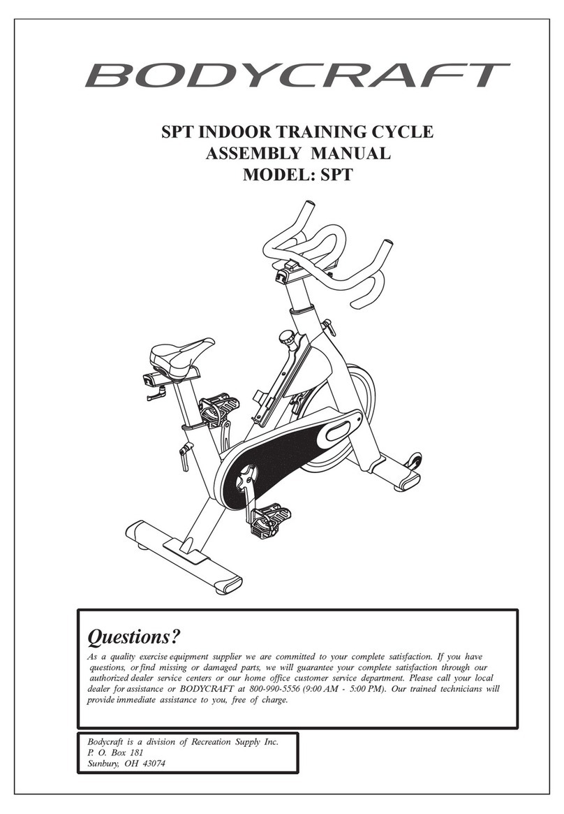
Body Craft SPT User manual

Body Craft
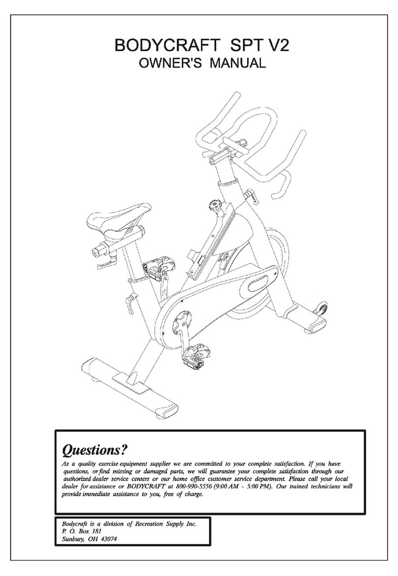
Body Craft V2 User manual

Body Craft
Body Craft RSI 300c User manual

Body Craft
Body Craft R25 User manual

Body Craft
Body Craft VF803J User manual

Body Craft
Body Craft R200 Recumbent User manual

Body Craft
Body Craft R1000G User manual

Body Craft
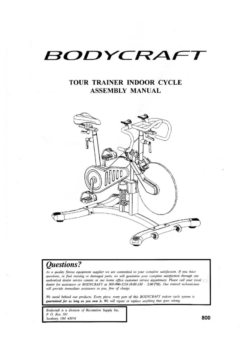
Body Craft Tour Trainer Indoor Cycle User manual

Body Craft
Body Craft TourTrainer none User manual

Body Craft
Body Craft R18 User manual