TOORX BRX 300 User manual

Ed : Rev : Cod :
INSTRUCTION
02/20 GRLDTOORXBRX300E00
iConsole App Manual
www.toorx.it/iconsole

Pre-assembly Notes
Open the boxes:
Make sure to inventory all the parts that are included in the box. Check the hardware chart
of a full count of the number of parts included for proper assembly . If any of the parts are
missing, contact with the dealer.
GATHER YOUR TOOLS
Before starting the assembly of your unit,gather the necessary tools.Having all of the
equipment at hand will save time and make the assembly quick and hassle-free.
NO.
NAME
SPECIFICATION
QUANTITTY
26
Allen C.K.S. half thread screw
M10×60×25
4
27
Spring washer
Φ10
8
28
Curved washer
Φ10.5×R100×t2.0
10
29
Philips pan head full thread screw
M4×6
6
33
Hex locking nut
M10
2
34
Flat washer
Φ10
2
35
Allen C.K.S. half thread screw
M10×20
4
36
Allen C.K.S. half thread screw
M10×55×20
2
37
Philips pan head full thread screw
M4×16
6

CLEAR YOUR WORK AREA
Make sure that you have cleared away a large enough space to properly assemble the
unit.Make sure the space is free from anything that may cause injury during
assembly.After the unit is fully assembled,make sure there is a comfortable amount of
free area around the unit for unobstructed operation.
NOTE: Each step number in the assembly instructions tells you what you will be doing.
Read and understand all instructions thoroughly before assembling the treadmill.
NAME
SPECIALIZED
QUANTITY
L-shaped wrench
5×80×80S(with a cross)
1
L-shaped wrench
6×40×120
1
Open-end wrench
t4.0×32×110
1

Product instruction
Technical information
*WE RESERVE THE RIGHT TO AMEND THE PRODUCT WITHOUT PRIOR NOTICE.
DIMENSION
Unfold:1090x560x1490mm
SPEED RATIO
8
UP&DOWN
9 levels, 270mm distance
FRONT&BACK
70mm distance
Motor belt
Console
Handle bar
Bottle
Bolt
Seat
Pedal
Front stabilizer
Back stabilizer

Step 1: Attach the front stabilizer (2) to the main frame (1) with curved washer(28), spring
washer(27) and Allen C.K.S. half thread screw(26).
Step 2: Attach the rear stabilizer (3) to the main frame (1) with curved washer(28), spring
washer(27) and Allen C.K.S. half thread screw(26).
Step 3:
Loosen the knob and attach saddle post(4)to the main frame. Then tighten the knob.
ASSEMBLY INSTRUCTIONS

Step 4:
1.Attach saddles(5) to the saddle post(4) with casing(25) and handle knobs(23), do not
tighten them.
2.Translate saddles(5) to proper position. Then attach saddle decoration cover (L)(16)
and saddle decoration cover (R)(17) to saddle post(4) with Philips C.K.S. pan head full
thread screw(29).
3.Tighten the handle knobs(23).
Step 5:
1.Attach the Upright post trim strip (46) to the Upper upright post (6). Take the Upright post

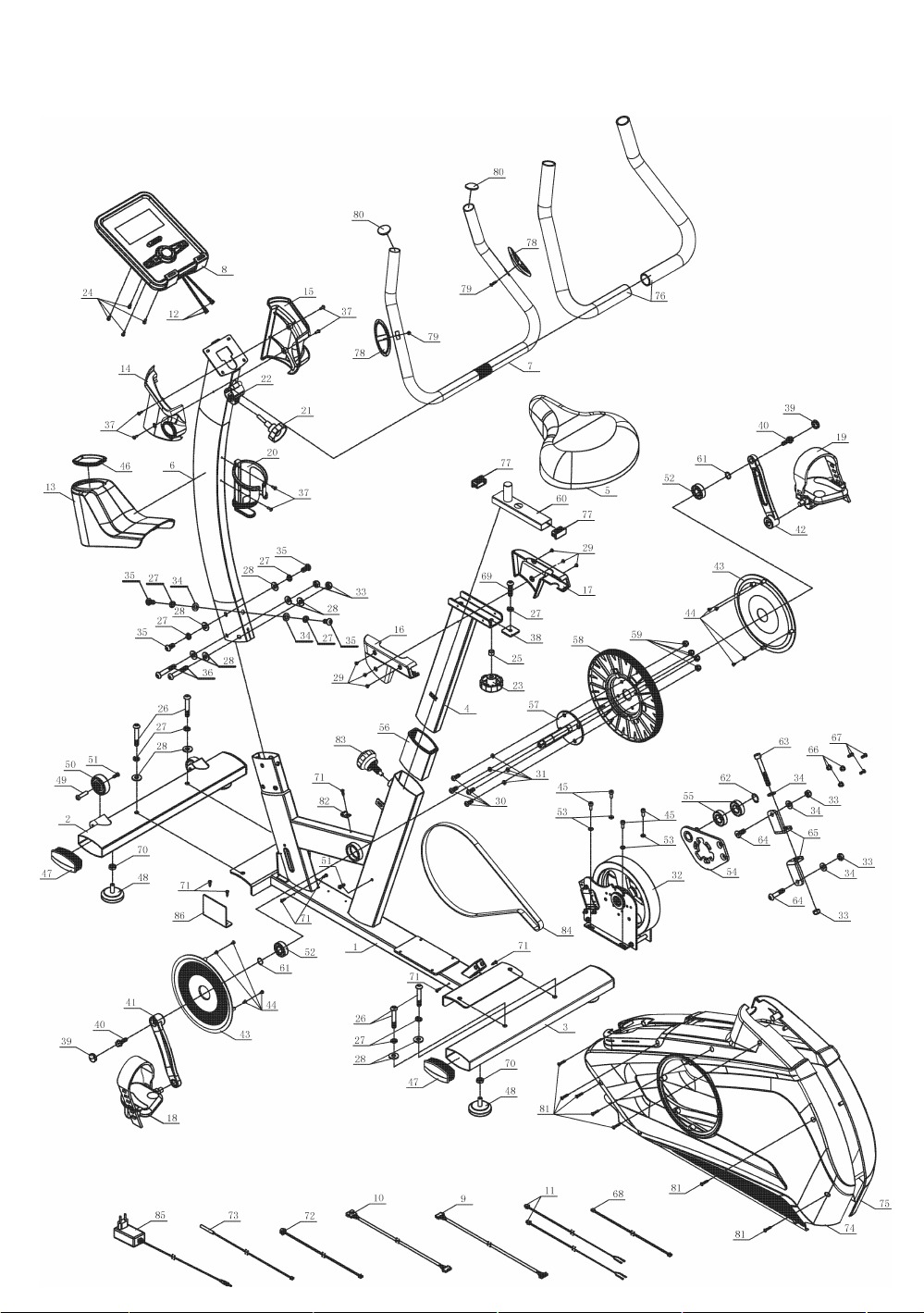
cover (13) from main frame (1). Then attach to the upper upright post (6).
2.Connect motor communication wire (10) and console communication wire (9).
3.Attach the upright post (6) to the main frame(1) with flat washer(34),spring
washer(27),Allen C.K.S. full thread screw(35), curved washer(28),spring
washer(27),Allen C.K.S. half thread screw(35), Allen C.K.S. half thread screw(36) ,curved
washer(28) and Hex locking nut.(33)
4. Attach upright post cover(13) and Upright post trim strip (46) to the main frame (1).
Tip: After connecting the communication line, it is necessary to plug the communication
wire into the upright post to avoid clipping the wire. Make sure that all screws are in the
hexagonal hole.
Step 6:
Attach handlebar connection wire(11) to the upright post(6). Attach handlebar(7) to the
upper upright post(6). Close handle clamp ring(22) and lock them with T-shaped rotary
knob(21).
6
13
1
9
10
46
28
27
34
27
35
34 27 35
28
27
35
36
28
33
28
35

Step 7:
1.Connect communication wire(9) and back hole of the console. Connect handle pulse
connection wire (11) and console outlet (12).
2.Attach console(8) to upper upright post (6) with Philips C.K.S. full thread screw(24).
3.Through handle bar cover left (14) and handle bar cover right (15 ) out of the
handlebar(7). Then attach them to upper upright post (6) with Philips pan head full thread
screw(37).
12
24 8
11
9
37
37
14
15
7
6
Step 8: Attach and lock left pedal(18) and right pedal(19) to the main frame(1).

Step 9:
Attach bottle holder(20) to upper upright post(6) with Philips pan head full thread
screw(37).
37
20
6
Workout tips:
1,User need to put the feet completely inside the pedal,and to adjust the resistance of
magnet control according to user.
2,Since the machine with double flywheels and it will have huge moment of inertia, when
the user stop before high speed, the user should minimize the resistance and lower the
speed, to avoid hurt the user’s leg by the moment of inertia of left and right pedal
3,The machine should be put on flat floor and have enough space for workout

Exploded Drawing for assembly

Part list
NO.
NAME
DESCRIPTION
QTY
1
Main frame
1
2
Front stabilizer
1
3
Rear stabilizer
1
4
Saddle post
1
5
Saddle
1
6
Upper Upright post
1
7
Handlebars
1
8
Console
1
9
Console communication wire
1
10
Motor communication wire
1
11
Handle pulse connection wire
2
12
Console outset
2
13
Upright post cover
1
14
Arm cover left
1
15
Arm cover right
1
16
Saddle cover(L)
1
17
Saddle cover(R)
1
18
Pedal(L)
1
19
Pedal(R)
1
20
Bottle holder
1
21
handle knob
1
22
Handlebar clamp ring
1
23
Handlebar rotary knob
Φ60×31×M10×20
1
24
Philips C.K.S. full thread screw
M5×10
4
25
Bushing tube
Φ10.5×Φ14×10
1
26
Allen C.K.S. half thread screw
M10×60×25
4
27
Spring washer
Φ10
9
28
Curved washer
Φ10.5×R100×t2.0
10
29
Philips pan head full thread screw
M4×6
6
30
Allen C.K.S. full thread screw
M8×20
4
31
Spring washer
Φ8
4

32
One-way EMS flywheel set
Φ215.4/Φ30
1
33
Hex locking nut
M10
5
34
Flat washer
Φ10
5
35
Allen C.K.S. full thread screw
M10×20
4
36
Allen C.K.S. half thread screw
M10×55×20
2
37
Philips pan head full thread screw
M4×16
6
38
Saddle locking piece
1
39
Crank cover
2
40
Hex flange full thread screw
5/16-18UNC-1"
2
41
Crank(L)
1
42
Crank(R)
1
43
Disc
2
44
Philips C.K.S. self-tapping screw
ST4×12
8
45
Hexagon socket head full tooth screw
M6×15
4
46
Upright post trim strip
1
47
End cap
4
48
Feet pad
4
49
Hexagon socket large flat head hollow
screw
Φ8×33×M6×15
2
50
Wheels
Φ55×25.8
2
51
Allen C.K.S. full thread screw
M6×15
3
52
Deep groove ball bearing
6203-2RS
3
53
flat washer
Φ6
4
54
pinch roller group
1
55
Deep groove ball bearing
6004ZZ
2
56
Saddle post bushing
1
57
Crank axis
Φ17×150
1
58
Belt pulley
Φ263×22
1
59
Hex locking nut
M8
4
60
Saddle adjustment
1
61
Circlip for shaft
Φ17
2
62
Circlip for shaft
Φ20
1
63
Hexagon socket head full tooth screw
M10×80
1

64
Hexagon countersunk head full tooth
screw
M10×25
1
65
Adjust the screw connection strap
2
66
Powder metallurgy set
Φ13×Φ8.5×8.4
3
67
Cross groove countersunk head full
tooth screw
M5×20
3
68
Brake cable
1
69
Hexagon socket pan head full tooth
screw
M10×38
1
70
Hex nut
M10
4
71
Philips C.K.S. self-tapping screw
ST4×16
8
72
Power communication wire
1
73
Magnetic sensor
1
74
Cover(L)
1
75
Cover(R)
1
76
Foam grip
Φ26×t3.0×600
2
77
Square pipe plug
20×40×t1.5
2
78
Handle pulse
2
79
Philips C.K.S. self-tapping screw
ST4×20
2
80
Round pipe plug
Φ28×t1.5
2
81
Philips C.K.S. self-tapping screw
ST4×25
7
82
Fixed magnet
1
83
Rotary hand bolt
1
84
Motor belt
450PJ6
1
85
Power adapter
1
86
controller
1

Half-drawing for assembly
20
37
26
3
1
2
27
29
29
16
37
18
19
27
28
14
15
6
13 17
4
28
26
21 7
11
12
24
8
9
22
5
46
25
23
9
10
28
27
34
27
35
34 27 35
28
27
35
36
28
33
28
35

Part list
NO.
NAME
DESCRIPTION
QTY
1
Main frame
1
2
Front stabilizer
1
3
Rear stabilizer
1
4
Saddle post
1
5
Saddle
1
6
Upper upright post
1
7
Handlebar post
1
8
Console
1
9
Console communication wire
1
10
Motor communication wire
1
11
Handle pulse connection wire
2
12
Console outlet wire
2
13
Upright post cover
1
14
Handlebar cover(L)
1
15
Handlebar cover(R)
1
16
Saddle cover(L)
1
17
Saddle cover(R)
1
18
Pedal(L)
1
19
Pedal(R)
1
20
Bottle holder
1
21
handle knob
1
22
Handlebar clamp ring
1
23
Handlebar rotary knob
Φ60×31×M10×20
1
24
Philips C.K.S. full thread screw
M5×10
4
25
Bushing tube
Φ10.5×Φ14×10
1
26
Allen C.K.S. half thread screw
M10×60×25
4
27
Spring washer
Φ10
8
28
Curved washer
Φ10.5×R100×t2.0
10
29
Philips pan head full thread screw
M4×6
6
33
Hex socking screw
M10
2
34
Flat washer
Φ10
2
35
Allen C.K.S. full thread screw
M10×20
4
36
Allen C.K.S. half thread screw
M10×55×20
2
37
Philips pan head full thread screw
M4×16
6
46
Upright post trim strip
1

CONSOLE
DISPLAY FUNCTIONS :
ITEM
DESCRIPTION
TIME
.Workout time displayed during exercise.
.Range 0:00 ~ 99:59
SPEED
.Workout speed displayed during exercise.
.Range 0.0 ~ 99.9
DISTANCE
.Workout distance displayed during exercise.
.Range 0.0 ~ 99.99
CALORIES
.Burned calories during workout display.
.Range 0 ~ 9999
PULSE
.Pulse bpm displayed during exercise.
.Pulse alarm when over preset target pulse.
RPM
.Rotation per minute
.Range 0 ~ 999
WATT
.Workout power consumption
. In Watt Program mode, computer will remain preset watt value
(setting range 0~350)
MANUAL
.Manual mode workout.
PROGRAM
.12 PROGRAM selection.
USER
.User creates resistance level profile.
H.R.C.
.Target HR training mode.

KEYS :
OPERATION:
POWER ON
Plug in power supply, computer will power on and display all segments on LCD for 2 seconds. After 4
minutes without pedaling or pulse input, console will enter into power saving mode.
Press any key may wake the console up.
WORKOUT SELECTION
Press UP and Down to select workout Manual →Beginner →Advance →Sporty →Cardio →Watt
Manual Mode
Press START in main menu may start workout in manual mode.
1. Press UP or DOWN to select workout program, choose Manual and press Mode to enter.
ITEM
DESCRIPTION
JOGGLE
WHEEL Up
‧Increase resistance level
JOGGLE
WHEEL Down
‧Decrease resistance level
Mode
‧Confirm setting or selection.
Reset
‧Hold on pressing for 2 seconds, computer will reboot and start from
user setting.
‧Reverse to main menu during presetting workout value or stop
mode.
Start/ Stop
‧Start or Stop workout.
Recovery
‧Test heart rate recovery status.
Body fat
‧Test body fat% and BMI.

2. Press UP or DOWN to preset TIME, DISTANCE, CALORIES, PULSE and press MODE to confirm.
3. Press START/STOP keys to start workout. Press UP or DOWN to adjust load level.
4. Press START/STOP keys to pause workout. Press RESET to reverse to main menu.
Beginner Mode
1. Press UP or DOWN to select workout program, choose Beginner mode and press Mode to enter.
2. Press UP or DOWN to preset TIME.
3. Press START/STOP key to start workout. Press UP or DOWN to adjust load level.
4. Press START/STOP key to pause workout. Press RESET to reverse to main menu.
Advance Mode
1. Press UP or DOWN to select workout program, choose Advance mode and press Mode to enter.
2. Press UP or DOWN to preset TIME.
3. Press START/STOP key to start workout. Press UP or DOWN to adjust load level.
4. Press START/STOP key to pause workout. Press RESET to reverse to main menu.
Sporty Mode
1. Press UP or DOWN to select workout program, choose Sporty mode and press Mode to enter.
2. Press UP or DOWN to preset TIME.
3. Press START/STOP key to start workout. Press UP or DOWN to adjust load level.
4. Press START/STOP key to pause workout. Press RESET to reverse to main menu.
Cardio Mode

1. Press UP or DOWN to select workout program, choose H.R.C. and press Mode to enter.
2. Press UP or Down to select 55%.75%.90% or TAG (TARGET H.R.) (default: 100).
3. Press UP or DOWN to preset workout TIME.
4. Press START/STOP key to start or stop workout. Press RESET to reverse to main menu.
Watt Mode
1. Press UP or DOWN to select workout program, choose WATT and press Mode to enter.
2. Press UP or DOWN to preset WATT target. (default: 120)
3. Press UP or DOWN to preset TIME.
4. Press START/STOP key to start workout. Press UP or DOWN to adjust Watt level.
5. Press START/STOP key to pause workout. Press RESET to reverse to main menu.
RECOVERY
1. After exercising for a period of time, keep holding on hand grips and press “RECOVERY” button.
All function display will stop except “TIME” starts counting down from 00:60 to 00:00.
2. Screen will display your heart rate recovery status with the F1, F2….to F6. F1 is the best, F6
F6 is the worst. User may keep exercising to improve the heart rate recovery status.
(Press the RECOVERY button again to return the main display.)
BODY FAT
1. In STOP mode, press the BODY FAT button to start body fat measurement.
2. Then selected user (U1~U4) will blinking for 2 seconds. Then start measuring.
3. During measuring, users have to hold both hands on the handgrip. And the LCD
will display “--” “--“for 8 seconds until computer finish measuring.
4. LCD will display BODY FAT advice symbol, BODY FAT percentage, BMI for 30
seconds.

“E-1”- Occurs when there is no heart rate signal input detected or user not hold
hand grips correctly.
“E-4” – Occurs when FAT% exceed setting range (5.0%~ 50%).
USB charger
This console provide USB port for tablet or mobile charge function only.
iConsole+APP
Turn on Bluetooth on tablet, search for console device and press connect.
Turn on iconsole+ app on tablet, and press connect to start workout with tablet.
(password: 0000)
NOTE:
1. Once console is connect to tablet via Bluetooth, the console will power off.
2. For iOS system, please exit iconsole app and turn off the Bluetooth from iPad, then the console
will power on again.
3. This system requires power supply 9v,1.3A or above.
Other manuals for BRX 300
1
Table of contents
Other TOORX Exercise Bike manuals

TOORX
TOORX BRX45 User manual

TOORX
TOORX BRX 100 User manual

TOORX
TOORX SRX60 EVO User manual

TOORX
TOORX SRX300 User manual

TOORX
TOORX BRX60 User manual

TOORX
TOORX BRX90 User manual

TOORX
TOORX BRX-R3000 User manual

TOORX
TOORX BRX AIR300 User manual

TOORX
TOORX BRX Compact User manual

TOORX
TOORX BRX30 User manual