BOETECH 150 User manual

Buffer Tank | 1
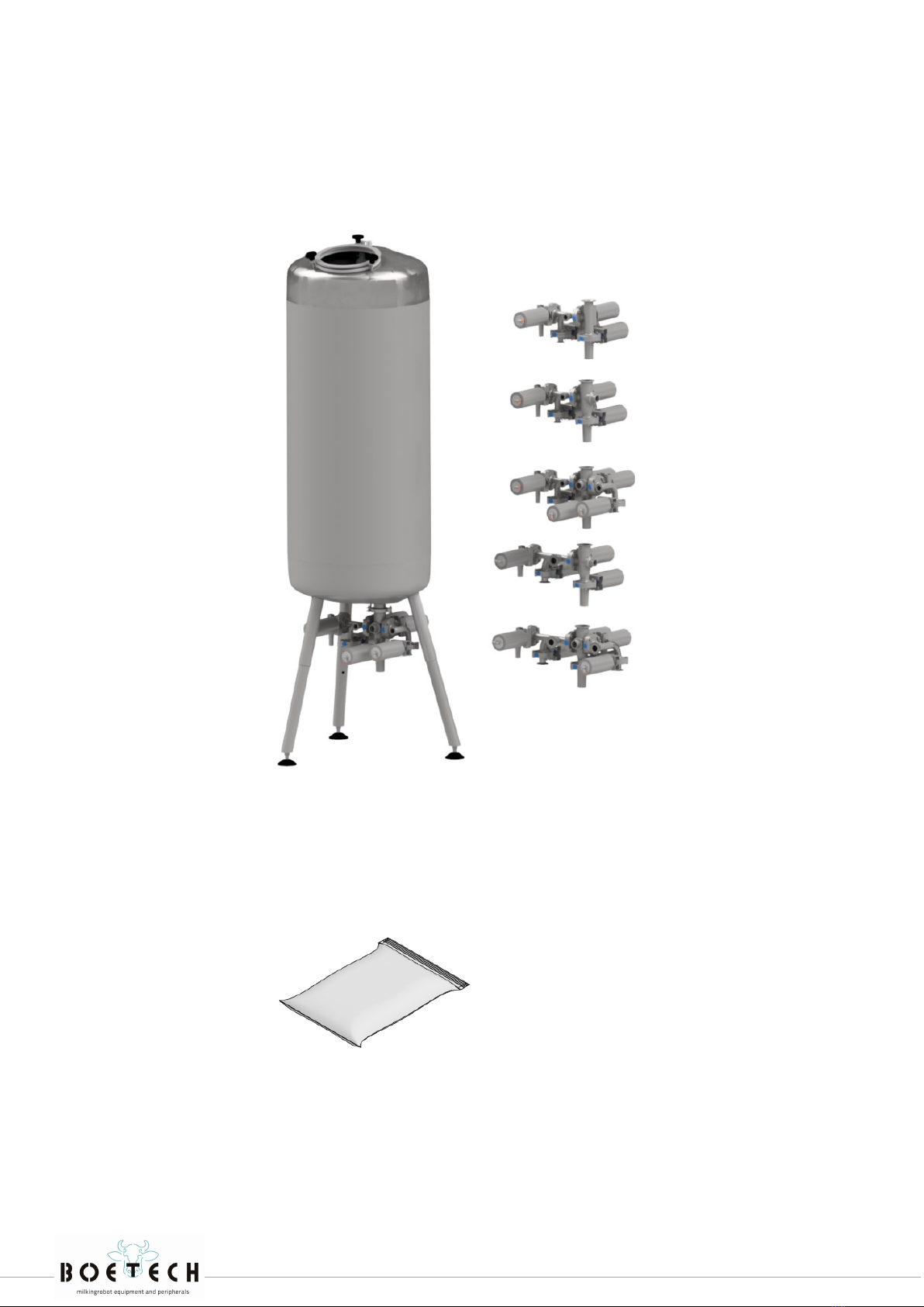
BUFFER TANK
Mounting Instructions
Buffer tank st./w. model 150
Buffer tank st./w. model 250
Buffer tank st./w. model 350
Buffer tank st./w. model 500
Buffer tank st./w. model 650
Buffer tank st. model 800
Buffer tank st. model 1000
Buffer tank st. model 1200
Buffer tank st. model 1600

Buffer Tank | 2
We thank you for choosing our product. These mounting instructions assist you in mounting
(and operating) the product safely. Product images are for illustrative purposes only and may
differ from the actual product.
Before you start the installation, make sure all supplied parts are present and have the right
measurements. This product has been manufactured under rigid inspection and quality ma-
nagement. We ask you to contact your sales department in case of a lack of clarity.
The type and the serial number of the buffer tank system are attached to the buffer valve
system. Always include the type and the serial number of your product, when you contact
your local Lely service provider or when ordering spare parts.
We suggest that you complete the table below with the type and the serial number of your
buffer tank system. Making your find the information easily.
Type number
Serial number
V3
Buffer Tank | 3
1
2

Buffer Tank | 4
PARTS
SPARE PARTS
Amount Article nr. Nr. Description
1x 1Buffer tank + valve system
1x 2144... 2Mounting set
English
Article nr. Description
100051 Actuator standard buffer system without bracket
100012 Spray nozzle for buffer tank
CONTENT
Sealing set Contains
214515
3 x EPDM seal 1” 100121
1 x EPDM seal 1,5” 100122
3 x Tri-Clamp seal DN 20 201079
1 x Tri-Clamp seal 2” 201072
214513
3 x EPDM seal 1” 100121
1 x EPDM seal 1,5” 100122
3 x Tri-Clamp seal DN 20 201079
1 x Tri-Clamp seal 2” 201072
1 x Silicone seal (levelsensor) 203021
214517
5 x EPDM seal 1” 100121
1 x EPDM seal 1,5” 100122
5 x Tri-Clamp seal DN 20 201079
1 x Tri-Clamp seal 2” 201072
1 x Silicon seal (levelsensor) 203021
214514
3 x EPDM seal DN25 100123
1 x EPDM seal 1,5” 100122
3 x Tri-Clamp seal DN25 720201
1 x Tri-Clamp seal 2” 201072
1 x Silicon seal (levelsensor) 203021
214518
5 x EPDM seal DN25 100123
1 x EPDM seal 1,5” 100122
5 x Tri-Clamp seal DN25 720201
1 x Tri-Clamp seal 2” 201072
1 x Silicon seal (levelsensor) 203021
Buffer Tank | 5
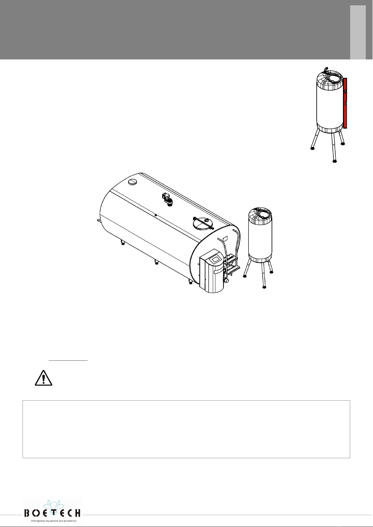
TANK PLACEMENT
1. Make sure the buffer tank is on a solid foundation. Use a level measuring instrument.
2. When a milk pipeline is placed at 30cm above the ground, there must be no walking
space between the buffer and the main tank.
3. The buffer tank should be located nearby or above the drain.
4. The best position to install your buffer tank is in front of the main tank. The distance
between the main tank and the buffer tank should be as short as possible. This will re-
duce operating costs and contributes to the deflate process.
AIR SUPPLY
A 6mm airline should be connected from the compressor to the valve block in the CRS+. 4mm airlines
must be connected to the butterfly valves underneath the buffer tank. The air pressure should be be-
tween 6 and 8 bars, to control the butterfly valves.
N.B. The air pressure to the butterfly valves should not be more than 8bar.
CLEANING
Clean the robot a couple of hours before using the buffer tank. When you do not do this, the robot
may proceed with the main cleaning process when the milk tank driver empties to the main tank.
English
MOUNTING INSTRUCTIONS

Buffer Tank | 6
INSTALLATION METHOD
1. Put the buffer tank into position.
2. Loosen all the lock nuts with the wrench.
3. Level your buffer tank by turning the leveling feet in and out as necessary.
4. When your buffer tank is level, tighten the lock nuts
using the wrench. Do not move your buffer tank unless
you tighten the locknuts. This may result in damage to the
leveling feet. Ensure that the buffer tank is stable.
5. Mount the air in/outlet (white elbow) on the top of the
buffer tank. Make sure this part is open and clean at all
times.
To make sure the buffer tank will not fall over, we recom-
mend attaching the cleaning pipe to a wall.
6. Make the tube/pipe connections according to the illustration beside. Connections can be made
with Pex or stainless steel.
English
MOUNTING INSTRUCTIONS

Buffer Tank | 7
Milk goes directly into the
mechanically refrigerated
main tank.
Milk goes into the buffer tank.
The main tank is being clean-
ing and rinsing.
The robot, milk pipeline and
buffer tank are being cleaned.
Milk is stored in the mechani-
cally refrigerated main tank.
Incorrect use of the buffer tank can be dangerous to people, nearby equipment and the environment. Before
reaching into the buffer tank, disconnect the air tubes of the CRS.
TROUBLESHOOTING
Issue Cause Action
Valve does not open or close properly Valve is broken Disassemble and replace part.
No voltage, no air pressure Check power supply, use air pressure to
check the valve
Buffer tank does not discharge water
properly No pressure Disassemble and check the air valve block,
increase the pressure.
High bacteria-count number Insufficient cleaning of the robot,
main tank or buffer tank
First check your robot cleaning, then sprin-
kle ball. Check for congestion in the tank
valve system.
INTEDED USE
English
Description ABC
150 Standing model
150 Wall model
60 cm
50 cm
150 cm
150 cm
180 cm
180 cm
250 Standing model
250 Wall model
60 cm
50 cm
230 cm
230 cm
260 cm
260 cm
350 Standing model
350 Wall model
60 cm
60 cm
220 cm
220 cm
250 cm
250 cm
500 Standing model
500 Wall model
98 cm
60 cm
190 cm
290 cm
220 cm
320 cm
650 Standing model 98 cm 230 cm 260 cm
800 Standing model 98 cm 230 cm 260 cm
1000 Standing model 98 cm 250 cm 280 cm
1200 Standing model 95 cm 280 cm 310 cm
1600 Standing model 140 cm 240 cm 300 cm
A = Diameter tank
B = Minimum height ceiling milk storage room
C = Advised height ceiling milk storage room. Note: Mini-
mum distance between the top of the buffer tank and the
ceiling should be 30 cm, for inspections.

Buffer Tank | 8
Connect the valves of the buffer tank with 4 air tubes (4mm, black PA) into the CRS+. Use the prede-
fined cluster configurations in the Lely CRS+ manual for the right settings and connections.
Menu item Description Min Max Default Unit
Maximum contents
The maximum content of the buffer tank is used
for an internal calculation to make sure the buffer
tank does not overflow.
200 2500 500 Kg
An alarm is generated when the buffer tank is full
(based on yield calculation of the milking robots).
All milking robots in the cluster will be taken out
of operation.
-441 -5511 -1102 (lb)
Maximum buffer time
The maximum time the milk is stored in the buffer
tank. When this time is expired, the milk will get
drained to the sewer. 4360 90 min
An alarm is generated when the set time is ex-
ceeded.
Buffer emptying time
The maximum time to allow the buffer tank to
transport the milk to the milk tank. This is based
on a full buffer tank.
360 60 min
The drain time depends on:
The location of the buffer tank concern-
ing the milk tank.
The amount of milk in the milk tank.
A sensor can be connected to the CRS+ indicating
when the buffer is empty.
If this sensor is installed, an alarm is generated
when the set time is exceeded.
The drainage pauses when a milking robot pumps
milk to the milk tank. The drain timer takes this
pause time into account.
Pre-rinse delay *
During pre-rinse valve V6 or V6b switches to
buffer after the set delay time. This is to prevent
milk residue to enter the buffer tank.
30 600 30 s
* Applicable for USA / Canada only.
English
APPENDIX A: CRS+/ CRS M3 BUFFER TANK SETTINGS

Buffer Tank | 9
Until May 2019 Valve plug connection
The level sensor is mounted at the lowest possible position in the tank valve
system of the buffer tank. The figure shows the correct wiring between the
level sensor and the CRS+ (3x 0,75mm2).
Note: When the red and green led lights are on, the buffer tank is empty.
From May 2019 M12 connector
A 3 or 4-wire cable is delivered with the system (colors brown, blue, black, [white])
CONNECTION LEVEL SENSOR TO CRS+ OR CRS M3
The sensor can be connected to an input of the CRS+ or CRS M3. Configure the setting: “BV is EMPTY
(BV1)” at ‘configuration inputs’. At ‘test inputs’ the state of the level sensor can be checked.
Check the functioning of the system at the first milk collection! Check the wiring if the “empty tank”
procedure does not work well.
Valve plug M12 CRS+ / CRS M3
1Blue - /GND
2Brown +
3Black Level high
English
APPENDIX B: LEVEL SENSOR (IF PRESENT)
Level high 24V on input CRS+/CRS M3 (black wire) Test inputs: BV is empty (BV1): full
No level 0V on input CRS+/CRS M3 (black wire) Test inputs: BV is empty (BV1): empty
Buffer Tank | 10
TROUBLESHOOTING
APPENDIX B: LEVEL SENSOR (IF PRESENT)
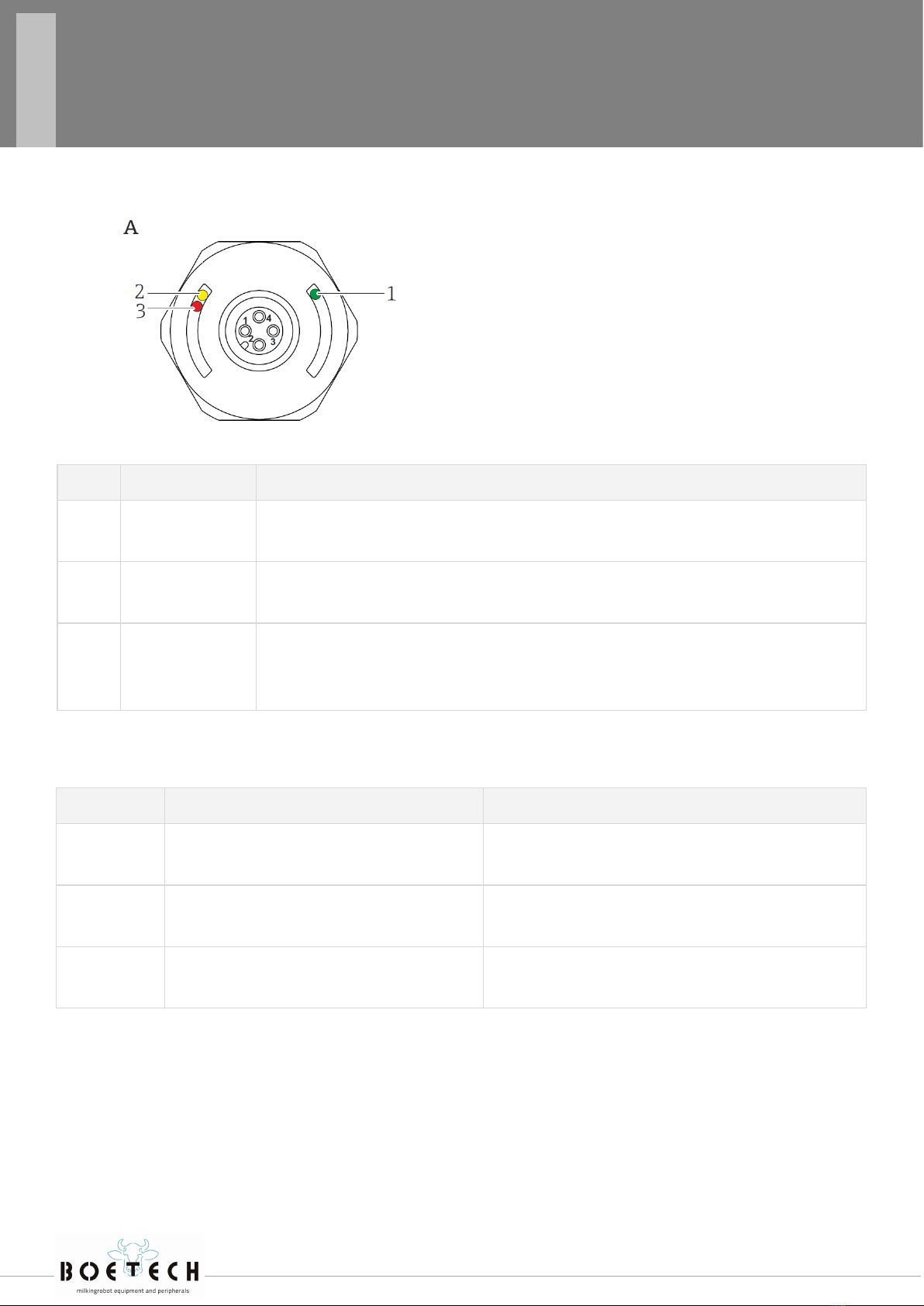
Item Fuction Description
1Green LED (gn)
Lit Device is operational
2Yellow LED (ye)
Lit
M12 connector
Indicates the sensor state: tuning fork is covered by liquid
3
Red LED (rd)
Flashing
Lit
Warning/maintenance required: error can be rectified, e.g. incorrect wiring
Fault/device failure: error cannot be rectified, e.g. electronic error
Malfunction Possible cause Corrective action
Green LED
Unlit No power supply Check connector, cable and power supply
Red LED
Flashing Overload or short-circuit in load circuit • Rectify short-circuit
• Reduce maximum load current to below 250 mA
Red LED
Lit Internal sensor failure or sensor corroded Replace device
English
AM12 connector, (cable without graphic)
LED DISPLAY LEVEL SENSOR M12 CONNECTOR (FROM MAY 2019)

Buffer Tank | 11
There are two options that you can choose:
• 203001 Electrical acted 3/2 valve
• 203008 Pneumatic acted 3/2 valve
The Pressure Reduce Valve should be adjusted as high as possible. In this situation the system will
work optimal.
MAX PRESSURE 1 - 1,2 bar!
203001 - Electrical acted 3/2 valve
This switchbox can be used for:
• Boetech switchbox
• CRS+
• CRS M3
With a Boetech switchbox the blow valve is con-
nected on terminals 37 + 38.
With CRS+ and CRS M3 a digital output ‘Boetech
air’ has to be configured.
English
APPENDIX C: PRESSURE SYSTEM
Pressure Air outlet Air inlet

Buffer Tank | 12
203008 - Pneumatic acted 3/2 valve
This switchbox can be used for:
• CRS M3
With CRS M3 a pneumatic output ‘Boetech air’ has to be configured
Pressure Air outlet Air inlet
4mm air output CRS ‘Boetech air’
APPENDIX C: PRESSURE SYSTEM
English

Buffer Tank | 13
English
PERSONAL NOTES

Buffer Tank | 14
PERSONAL NOTES
English

Buffer Tank | 15
All rights reserved. The information given in this publication is provided for information purposes only
and does not constitute an offer for sale. Certain products may not be available in individual countries
and products supplied may differ from those illustrated.
No part of this publication may be copied or published by means of printing, photocopying, microfilm or
any other process whatsoever without prior permission in writing by Boetech Meps Int. B.V.
Although the contents of this publication have been compiled with the greatest possible care, Boetech
Meps Int. B.V. cannot accept liability for any damage that might arise from errors or omissions in this
publication. The English language manual is the original manual. Translations into other languages use
the English language manual as the source document. Boetech Meps Int. B.V. accepts no liability for
discrepancies between the original English language manual and versions in other languages. If there is
a conflict over the content and accuracy of any translated manual, the English language manual is the
authority document.
Copyright © 2020 Boetech Meps Int. B.V.
All rights reserved
COPYRIGHT AND DISCLAIMER
Antennestraat 38
1322 AE Almere
The Netherlands
www.boetech.nl www.boetechmeps.com

Buffer Tank | 16
Antennestraat 38
1322 AE Almere
The Netherlands
www.boetech.nl www.boetechmeps.com
This manual suits for next models
8
Popular Tank Equipment manuals by other brands


Astro Pneumatic Tool
Astro Pneumatic Tool PT2-4 quick start guide

Franklin Fueling Systems
Franklin Fueling Systems EVO 600 Operation guide

TransTank
TransTank TopCrop Operator's handbook

WELBA
WELBA TW-32 quick start

Amtrol
Amtrol FILL-TROL FT-109 Installation & operation instructions

Regulus
Regulus RBC 200 Installation and operation manual


