Bohler MT G Series User manual

1
Firmenname oder Division
www.voestalpine.com
Lasting Connections
MIG MAG
WELDING TORCH
voestalpine Böhler Welding
www.voestalpine.com/welding

2
Functions ....................................3
Deutsch.......................................4
English.......................................10
Français ....................................16
Español.....................................22
voestalpine Böhler Welding Group GmbH
www.voestalpine.com/welding
Peter-Müller-Straße 14-14a
40468 Düsseldorf
Germany
3
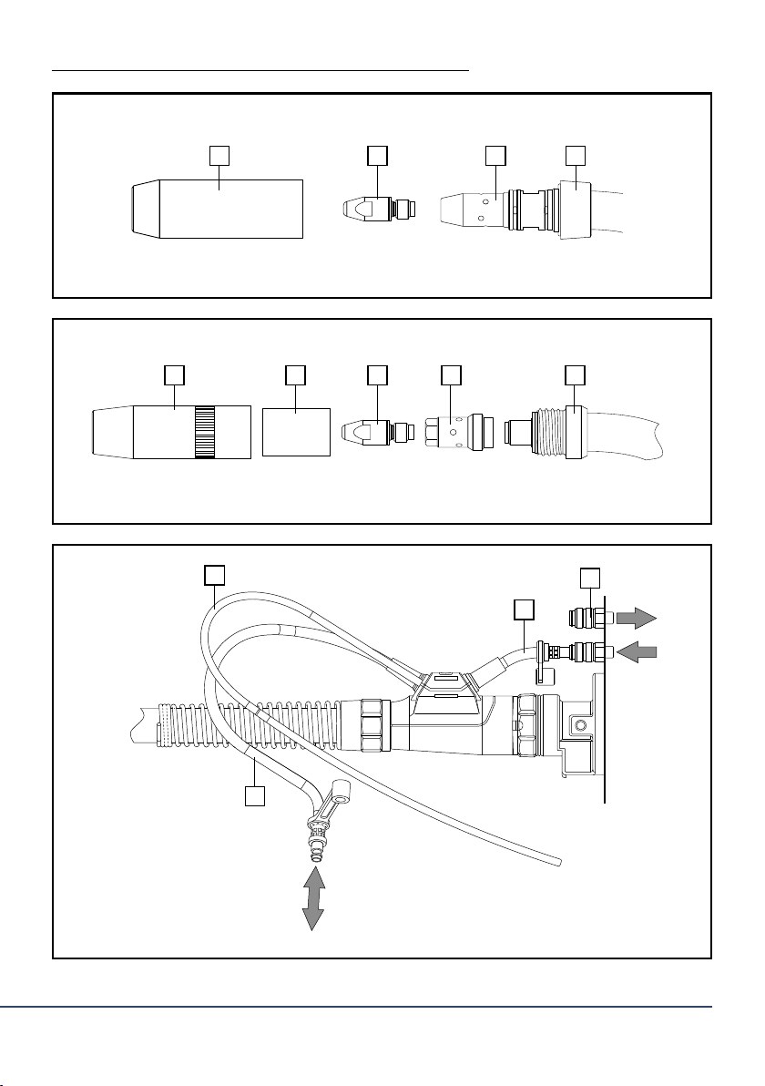
Fig. 1 - MT G ausrüsten / Setting up MT G / Équipement des torches MT G / Equipamiento de la MT G
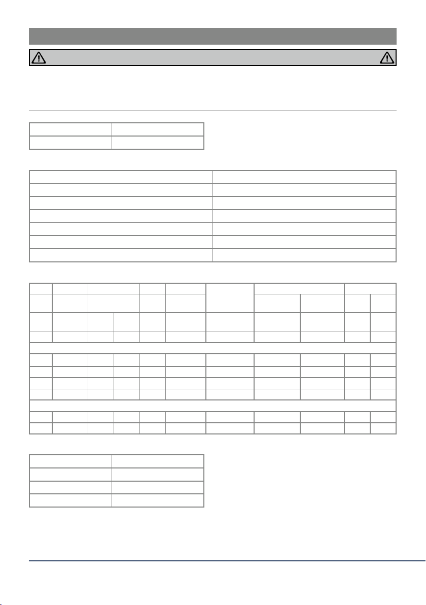
Fig. 2 - MT W ausrüsten / Setting up MT W / Équipement des torches MT W / Equipamiento de la MT W
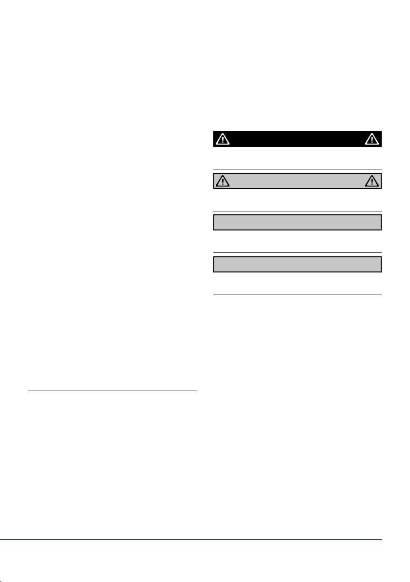
Fig. 3 - Kühlmittel anschließen / Connecting the coolant / Connecter le liquide de refroidissement / Conexión del refrigerante
1
1
2
2
3
3 4
4
5
1
4
2
3
Funktionen / functions / fonctions / función

4Deutsch
ORIGINAL BETRIEBSANLEITUNG
Der Hersteller behält sich das Recht vor, jederzeit und ohne vorherige Mitteilung Änderungen an dieser Betriebsanleitung durch-
zuführen, die durch Druckfehler, eventuelle Ungenauigkeiten der enthaltenen Informationen oder Verbesserung dieses Produktes
erforderlich werden. Diese Änderungen werden jedoch in neuen Ausgaben berücksichtigt.
Alle in der Betriebsanleitung genannten Handelsmarken und Schutzmarken sind Eigentum der jeweiligen Besitzer/Hersteller.
Die Kontaktdaten der voestalpineBöhler WeldingLändervertretungen und Partner weltweit entnehmen Sie bitte unserer Homepage
www.voestalpine.com/welding.
INHALT
1. IDENTIFIKATION
2. SICHERHEIT
1. Identifikation
1.1 Kennzeichnung
2. Sicherheit
2.1 Sicherheitshinweise
2.2 Bestimmungsgemäße Verwendung
2.3 Klassifizierung der Warnhinweise
2.4 Angaben für den Notfall
3. Produktbeschreibung
3.1 Technische Daten
3.2 Verwendete Zeichen und Symbole
4. Inbetriebnahme
4.1 Brenner ausrüsten
4.2 MT G mit steckbarer Gasdüse und Düsenstock
4.3 MT W flüssiggekühlt
4.4 Drahtführung montieren
4.4.1 Führungsspirale
4.4.2 Kunststoffseele
4.5 Schlauchpaket maschinenseitig montieren
4.6 Kühlmittel anschließen
4.7 Schutzgasmenge einstellen
4.8 Draht einfädeln
4.9 Bedienelemente Brennerhandgriff
4.9.1 Taster Funktion
5. Betrieb
6. Außerbetriebnahme
7. Wartung und Reinigung
7.1 Brennerhals wechseln
8. Entsorgung
9. Gewährleistung
Die MIG-MAG Handschweißbrenner werden zum sicheren
Schweißen von niedrig- und hochlegierten Werkstoffen einge-
setzt. Sie bestehen aus dem Brennerhals mit Ausrüst- und
Verschleißteilen, Brennerhandgriff und Schlauchpaket mit
Zentralanschluss. Sie entsprechen der EN 60 974-7 und stellen
kein Gerät mit eigener Funktionserfüllung dar.
Das Lichtbogenschweißen wird erst in Verbindung mit der
Schweißstromquelle möglich.
1.1. Kennzeichnung
Das Produkt erfüllt die geltenden Anforderungen des jeweiligen
Marktes für das Inverkehrbringen. Sofern es einer entsprechen-
den Kennzeichnung bedarf, ist diese am Produkt angebracht.
2.1. Sicherheitshinweise
ʸLesen Sie die vorliegende Betriebsanleitung vor der ersten
Nutzung sorgfältig durch und befolgen Sie diese.
ʸDie vorliegende Betriebsanleitung vermittelt Ihnen die In-
formationen, die für einen störungsfreien und sicheren
Betrieb erforderlich sind. Das Produkt wurde nach dem Stand
der Technik und den anerkannten sicherheitstechnischen
Normen und Richtlinien entwickelt und gefertigt.
ʸVor unvermeidbaren Restrisiken für Anwender, Dritte, Ge-
räteoder andere Sachwerte werden in derBetriebsanleitung
gewarnt. Die verwendeten Sicherheitshinweise weisen auf
konstruktiv nicht vermeidbare Restrisiken hin, die beachtet
und befolgt werden müssen.
ʸEin Nichtbeachten dieser Sicherheitshinweise kann zur Ge-
fahr für das Leben, Gesundheit von Personen, Umweltschä-
den oder zu Sachschäden führen. Das Produkt ist nur in
einwandfreiem Zustand, unter Beachtung der Betriebsan-
leitung zu betreiben.
ʸFür Schäden diedurch Nichtbeachtung der Betriebsanleitung
entstehen, übernimmt der Hersteller keine Haftung.
ʸSchützen Sie sich und unbeteiligte Personen mit geeigneten
Mitteln vor denen im Sicherheitskapitel aufgeführten Ge-
fahren.
Grundlagen:
ʸLesen Sie die Betriebsanleitung vor spezifischen Arbeiten
z.B. Inbetriebnahme, Betrieb, Transport und Wartung gründ-
lich durch und befolgen Sie diese.
ʸHalten Sie die Betriebsanleitung zum Nachschlagen am
Gerät bereit und geben Sie die Betriebsanleitung bei Wei-
tergabe des Produktes mit.
ʸBeachtenSiedieBetriebsanleitungender einzelnenschweiß-
technischenKomponenten, wiez.B: Schweißstromquelle und
Drahtvorschubgerät.
ʸEntnehmen Sie die Handhabung von Gasflaschen den
AnweisungenderGasHerstellerundderDruckgasverordnung.
ʸBeachtenSie die Unfallverhütungsvorschriftendes jeweiligen
Landes.
ʸInbetriebnahme,Bedienungs- und Wartungsarbeiten dürfen
nur von Fachkräften durchgeführt werden. Eine Fachkraft
ist eine Person, die aufgrund ihrer fachlichen Ausbildung,
Kenntnisse und Erfahrungen sowie Kenntnis der einschlägi-
gen Normen die ihr übertragenen Arbeiten beurteilen und
mögliche Gefahren erkennen kann.
- Deutsch -
MT G
MT W
Betriebsanleitung - MIG/MAG Schweißbrenner
GEFAHR

5
Deutsch
2.2. Bestimmungsgemäße Verwendung:
ʸDas in dieser Anleitung beschriebene Gerät darf ausschließ-
lich zu dem in der Anleitung beschriebenen Zweck in der
beschriebenen Art und Weise verwendet werden. Beachten
Sie dabei die Betriebs-, Wartungs- und lnstandhaltungs-
bedingungen.
ʸJede andere Verwendung gilt als nicht bestimmungsgemäß.
ʸEigenmächtigeUmbautenoderVeränderungenzurLeistungs-
steigerung sind nicht zulässig.
2.3. Klassifizierung der Warnhinweise:
Die in der Betriebsanleitung verwendeten Warnhinweise sind
in vier verschiedene Ebenen unterteilt und werden vor poten-
ziell gefährlichen Arbeitsschritten angegeben. Geordnet nach
abnehmender Wichtigkeit bedeuten sie folgendes:
2.4. Angaben für den Notfall:
Unterbrechen Sie im Notfall sofort folgende Versorgungen:
ʸElektrische Energieversorgung
ʸKühlmittelzufuhr
ʸGaszufuhr
Weitere Maßnahmen entnehmen Sie der Betriebsanleitung der
Stromquelle oder der Dokumentation weiterer Peripherie-
geräte.
Bezeichnet eine unmittelbar drohende Gefahr. Wenn sie nicht
gemieden wird, sind Tod oder schwerste Verletzungen die
Folge.
Bezeichnet eine möglicherweise gefährliche Situation. Wenn
sie nicht gemieden wird, können schwere Verletzungen die
Folge sein.
Bezeichnet eine möglicherweise schädliche Situation. Wenn sie
nicht gemieden wird, können leichte oder geringfügige Verlet-
zungen die Folge sein.
Bezeichnet die Gefahr, dass Arbeitsergebnisse beeinträchtigt
werden oder Sachschäden an der Ausrüstung die Folge sein
können.
- Deutsch -
ʸSorgen Sie für eine gute Beleuchtung des Arbeitsbereiches
und halten Sie den Arbeitsbereich in Ordnung.
ʸSchalten Sie für die gesamte Dauer von Wartungs-, Inbe-
triebnahme-, Instandhaltungs- und Reparaturarbeiten die
Stromquelle aus, Gaszufuhr und Druckluft ab, ziehen Sie
den Netzstecker.
ʸBeachten Sie bei der Entsorgung die örtlichen Bestimmun-
gen, Gesetze, Vorschriften, Normen und Richtlinien.
Elektrotechnik:
ʸÜberprüfen Sie das Elektrowerkzeug auf eventuelle Beschä-
digungen und auf ihre einwandfreie und bestimmungs-
gemäße Funktion.
ʸSetzen Sie die Elektrowerkzeuge nicht dem Regen aus und
vermeiden Sie eine feuchte oder nasse Umgebung.
ʸSchützen Sie sich vor elektrischen Schlag, indem Sie isolie-
rendeUnterlagenverwendenundtrockeneKleidungtragen.
ʸVerwenden Sie die Elektrowerkzeuge nicht in Bereichen, wo
Brand- oder Explosionsgefahr besteht.
Schweißen:
ʸLichtbogenschweißen kann Augen, Haut und Gehör schä-
digen! Tragen Sie deshalb immer die vorgeschriebene
Schutzkleidung, Augen- und Gehörschutz gemäß der ein-
schlägigen Vorschriften des entsprechenden Landes.
ʸAlle Metalldämpfe, besonders Blei, Cadmium, Kupfer und
Beryllium, sind schädlich! Sorgen Sie für ausreichende Be-
lüftung oder Absaugung. Überschreiten Sie nicht die gel-
tenden Arbeitsplatzgrenzwerte (AGW).
ʸSpülen Sie Werkstücke, die mit chlorierten Lösungsmitteln
entfettet wurden, mit klarem Wasser ab. Ansonsten besteht
die Gefahr der Phosgengasbildung. Stellen Sie keine chlor-
haltigen Entfettungsbäder in der Nähe des Schweißplatzes
auf.
ʸIn Verbindung mit diversen Schweißbrennern können wei-
tere Gefahren auftreten, z.B. durch: elektrischen Strom
(Stromquelle,interner Stromkreis), Schweißspritzer imHinblick
auf brennbare oder explosionsgefährliche Stoffe, UV-Strah-
lung des Lichtbogens, Rauch und Dämpfe.
ʸHalten Sie die allgemeinen Brandschutzbestimmungen ein
und entfernen Sie vor Arbeitsbeginn feuergefährliche
Materialien aus der Umgebung des Schweißarbeitsplatzes.
Stellen Sie geeignete Brandschutzmittel am Arbeitsplatz
zur Verfügung.
Technischer Zustand:
ʸÜberschreiten Sie nicht die Belastungsdaten der maximalen
Grenzwerte. Überlastungen führen zu Zerstörungen.
ʸNehmen Sie keine baulichen Veränderungen an diesem
Gerät vor.
ʸVerwenden Sie beim Gebrauch im Freien einen geeigneten
Schutz gegen Witterungseinflüsse.
Schutzkleidung:
ʸTragen Sie keine weite Kleidung oder Schmuck.
ʸTragen Sie bei langen Haaren ein Haarnetz.
ʸTragen Sie im Betrieb und in Verbindung mit dem Schweiß-
prozess Schutzbrille, Schutzhandschuhe und ggf. Atem-
maske.
WARNUNG
VORSICHT !
HINWEIS
GEFAHR
6
3. PRODUKTBESCHREIBUNG
Deutsch
- Deutsch -
Bei nicht bestimmungsgemäßer Verwendung können vom Gerät Gefahren für Personen, Tiere und Sachwerte ausgehen.
ʸGerät ausschließlich bestimmungsgemäß verwenden.
ʸGerät nicht eigenmächtig zur Leistungssteigerung umbauen oder verändern.
ʸJegliche Arbeiten am Gerät bzw. System sind ausschließlich befähigten Personen vorbehalten.
WARNUNG Gefahren durch nicht bestimmungsgemäße Verwendung!
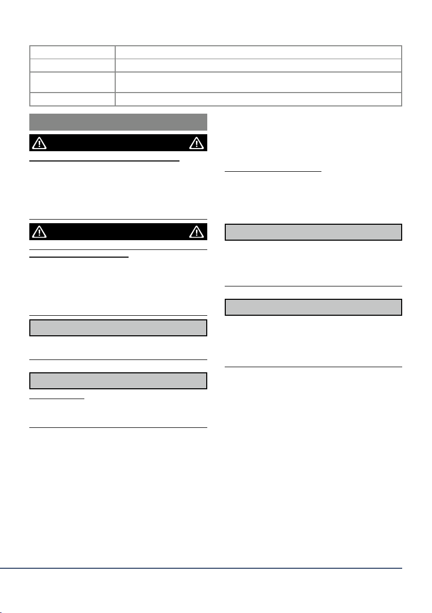
Transport und Lagerung -25 °C bis +55°C
Relative Luftfeuchte bis 90% bei 20°C
Tab. 1 Umgebungsbedingungen im Betrieb
Standardlänge L 3,00 m / 4,00 m
Kühlmittelanschluss Stecknippel NW 5
Kühlgeräteleistung min. 800 W
Steuerleitung 2-adrig
Tab. 4 Schlauchpaket
Spannungsart DC
Polung der Elektroden bei DC in der Regel positiv
Schutzgas (DIN EN ISO 14175) CO2und Mischgas M21
Drahtarten handelsübliche Runddrähte
Spannungsbemessung 113 V Scheitelwert
Schutzart der maschinenseitigen Anschlüsse (EN 60 529) IP3X
Steuereinrichtung im Brennerhandgriff für 42 V und 0,1 bis 1 A
Tab. 2 Allgemeine Brennerdaten nach EN 60 974-7
Typ Kühlart Belastung ED DRAHT- Ø Gasdurchfluss Kühlung Fließdruck
Einkreis Standard
Lichtbogen
CO2M21 Vorlauftemp.
max
Durchfluss
min.
min max
AA%mm l/min °C l/min bar bar
MT G Serie
150 luft 170 170 60 0,6 - 1,0
250 luft 230 220 60 0,8 - 1,2
300 luft 280 260 60 0,8 - 1,2
350 luft 330 310 60 1,0 - 1,6
MT W Serie
440 flüssig 500 450 100 0,8 - 1,6 10 - 20 50 1,5 1,5 3,5
540 flüssig 600 550 100 1,0 - 1,6 10 - 20 50 1,5 1,5 3,5
Tab. 3 Produktspezifische Brennerdaten (EN 60 974-7) MT G und MT W
3.1. Technische Daten

7
4. INBETRIEBNAHME
Deutsch
- Deutsch -
4.1. Brenner ausrüsten
3.2. Verwendete Zeichen und Symbole:
In der Betriebsanleitung werden folgende Zeichen und Symbole verwendet:
Symbol Beschreibung
ʸAufzählungssymbol für Handlungsanweisungen und Aufzählungen
-> Querverweissymbol verweist auf detaillierte, ergänzende oder weiterführende Informationen
1. Handlungsschritt/e im Text, die der Reihenfolge nach durchzuführen sind
Verletzungsgefahr durch unerwarteten Anlauf
Für die gesamte Dauer von Wartungs-, Instandhaltungs-,
Montage- bzw. Demontage- und Reparaturarbeiten ist Folgen-
des zu beachten:
ʸSchalten Sie die Stromquelle aus.
ʸSperren Sie die Gaszufuhr ab.
ʸSperren Sie die Kühlmittelzufuhr ab.
ʸTrennen Sie alle elektrischen Verbindungen.
Verletzungsgefahrund Geräteschädendurch unautorisierte
Personen
Unsachgemäße Reparaturen und Änderungen am Produkt
können zu erheblichen Verletzungen und Geräteschäden
führen. Die Produktgarantie erlischt bei Eingriff durch
unautorisierte Personen.
ʸJegliche Arbeiten am Gerät bzw. System sind ausschließlich
befähigten Personen vorbehalten.
GEFAHR
GEFAHR
Beachten Sie folgende Angaben:
-> 3. PRODUKTBESCHREIBUNG auf Seite 6
ʸSetzen Sie nur gasdichte, mit Kunststoff isolierte Drahtfüh-
rungen ein, um eine sichere Schutzgasabdeckung sowie
eine definierte Stromkontaktierung zu gewährleisten.
ʸBlanke Führungsspiralen führen zu Schutzgasverlust.
ʸNeue noch unbenutzte Führungsspiralen müssen auf die
tatsächliche Schlauchpaketlänge gekürzt werden.
ʸBei feststehenden Brennerhälsen werden nur durch-
gehende Führungsspiralen verwendet.
ʸUm die Drahtführung mit etwas Vorspannung installieren
zu können, ist ein Übermaß erforderlich.
HINWEIS
HINWEIS
HINWEIS
Verletzungsgefahr
Durch- bzw. Einstich durch Drahtelektrode.
ʸGreifen Sie nicht in den Gefahrenbereich.
ʸTragen Sie entsprechende Schutzhandschuhe.
VORSICHT !
4.2. MT G mit steckbarer Gasdüse und Düsenstock
MT G ausrüsten (Fig. 1 / S. 3)
1 - Gasdüse steckbar
2 - Stromdüse
3 - Düsenstock steckbar
4 - Übergangsstück
4.3. MT W flüssiggekühlt
MT W ausrüsten (Fig. 2 / S. 3)
1 - Gasdüse
2 - Spritzerschutz (sofern vorhanden)
3 - Stromdüse
4 - Düsenstock
5 - Brennerhals
4.4. Drahtführung montieren
4.4.1. Führungsspirale
MT G/ MT W
Zur Verwendung von Stahldrähten bei nicht geteilter Draht-
führung.
1. Schlauchpaket gestreckt auslegen, Gasdüse und Strom-
düse vom Brennerhals abschrauben.
2. Überwurfmutter am Zentralstecker oder Einzelanschluss
abschrauben und Führungsspirale durch Schlauchpaket
bis zum Haltenippel einschieben.
3. Überwurfmutter wieder aufschrauben, mit beiliegendem
Schlüssel festziehen und Überlänge von Führungsspirale
bündig am Düsenstock abschneiden.
4. Stromdüse und Gasdüse montieren.
Rüsten Sie den Brennerhals gemäß der Abbildung aus
(Fig. 2 / S. 3):
1. Auswechselbaren Düsenstock (4) auf Brennerhals (5)
aufschrauben und Düsenstock (4) mit dem beiliegenden
Schlüssel festziehen.
2. Stromdüse (3) in Düsenstock (4) schrauben.
3. Stromdüse (3) mit dem beiliegenden Schlüssel festziehen.
Sofern noch kein Spritzerschutz vorhanden ist:
4. Spritzerschutz (2) von der Rückseite der Gasdüse (1)
einführen.
5. Gasdüse (1) mit Spritzerschutz (2) aufschrauben.
Der Spritzerschutz (2) schiebt sich hierbei in die korrekte
Position innerhalb der Gasdüse (1).

8Deutsch
- Deutsch -
ʸAchten Sie darauf, dass Kühlmittelvor- und rücklauf
ordnungsgemäß installiert sind. Kühlmittelvorlauf = blau,
Kühlmittelrücklauf = rot.
ʸVerwenden Sie kein deionisiertes oder demineralisiertes
Wasser als Kühlmittel oder für Dichtheits- und Durchfluss-
prüfungen. Dies kann die Lebensdauer Ihres Schweißbren-
ners beeinträchtigen.
ʸWir empfehlen für flüssiggekühlte Schweißbrenner die
Verwendung von Böhler Welding eigenem Kühlmittel.
4.7. Schutzgasmenge einstellen
ʸArt und Menge des zu verwendenden Schutzgases hängt
von der Schweißaufgabe und der Gasdüsengeometrie ab.
ʸStellen Sie alle Schutzgasverbindungen gasdicht her.
ʸUm eine Verstopfung durch Verunreinigung in der Schutz-
gasversorgung zu verhindern, müssen Sie das Flaschen-
ventil vor dem Anschluss kurz öffnen. Dadurch werden evtl.
Verunreinigungen ausgeblasen.
ʸAchten Sie bei jedem Drahtwechsel auf einen gratfreien und
unverbogenen Drahtanfang.
ʸJegliche Arbeiten am Gerät bzw. System sind ausschließlich
befähigten Personen vorbehalten.
ʸBeachten Sie die Dokumentation der schweißtechnischen
Komponenten.
Mit dem Standard Schweißbrenner ist eine 2-Takt Betriebsart
des Tasters möglich.
Weitere Betriebsarten (z.B. 4-Takt) und Brennerhandgriff-
module sind abhängig von der jeweiligen Stromquelle und
müssen separat bestellt werden.
4.9.1. Taster Funktion
1. Taster am Brennerhandgriff drücken und halten =
Schweißstart.
2. Taster loslassen = Schweißende.
HINWEIS
HINWEIS
HINWEIS
HINWEIS
Verletzungsgefahr
Durch- bzw. Einstich durch Drahtelektrode.
ʸGreifen Sie nicht in den Gefahrenbereich.
ʸTragen Sie entsprechende Schutzhandschuhe.
VORSICHT !
4.5. Schlauchpaket maschinenseitig montieren
1. Zentralstecker und die Zentralbuchse am Drahtvorschub-
gerät zusammenfügen.
2. Beide mit der Anschlussmutter sichern.
3. Bei MT W die Anschlüsse für Kühlmittelvor- und -rücklauf
montieren.
4. Schutzgas- und Steuerleitungsstecker bei anderen Ma-
schinenanschlüssen montieren.
4.6. Kühlmittel anschließen
1. Maschinenseitig angeschlossenes Schlauchpaket
gestreckt auslegen.
2. Draht nach Angaben des Herstellers in das Drahtvor-
schubgerät einlegen.
3. Drucktaster „Stromloser Drahtvorschub“ am Drahtvor-
schubgerät betätigen, bis der Draht aus der Stromdüse
herausläuft.
4.9. Bedienelemente Brennerhandgriff
Verbrennungsgefahr
Das Schlauchpaket wird durch zu geringen Kühlmittelstand
überhitzt.
ʸTragen Sie entsprechende Schutzhandschuhe.
ʸÜberprüfen Sie regelmäßig den Kühlmittelstand.
Kühlmittel anschließen (Fig. 3 / S. 3)
1 - Steuerleitung
2 - Kühlmittelvorlaufschlauch
3 - Umlaufkühlgerät
4 - Kühlmittelrücklaufschlauch
WARNUNG
4.8. Draht einfädeln
ʸNeue noch unbenutzte Kunststoffseelen müssen auf die
tatsächliche Schlauchpaketlänge gekürzt werden.
ʸBei Kunststoffseelen mit Außendurchmesser 4,00 mm muss
das Kapillarrohr im Zwischenanschluss durch ein Führungs-
rohr ersetzt werden.
ʸBei wechsel- und umsteckbaren und nicht wechselbaren
Brennerhälsen kommen Kombi-Drahtführungen mit ange-
prägter Messingspirale zum Einsatz.
ʸBei wechselbaren Brennerhälsen wird eine Brennerhals-
spirale aus Messing verwendet.
HINWEIS
Zur Verwendung von Aluminium-, Kupfer-, Nickel- und Edel-
stahldrähten:
1. Schlauchpaket gestreckt auslegen, Stromdüse einschrau-
ben.
2. Drahtführung mit der Messingspirale zuerst durch das
Schlauchpaket bis zum spürbaren Anschlag an die Strom-
düse schieben.
3. Klemmnippel, O-Ring und Überwurfmutter auf die Kunst-
stoffseele stecken und unter Spannung die Überwurfmut-
ter festschrauben.
4. Überlange Kunststoffseele vor den Drahtförderrollen
markieren und mit dem Cutter an der Markierung ab-
schneiden.
4.4.2. Kunststoffseele ʸBei jeder Erstinbetriebnahme bzw. nach jedem Schlauch-
paketwechsel müssen Sie das Kühlsystem entlüften: Kühl-
mittelrücklauf von Umlaufkühlgerät lösen, über Auffang-
behälter halten. Öffnung am Kühlmittelrücklauf verschließen.
Durch wiederholtes, abruptes Öffnen wieder frei geben, bis
Kühlmittel kontinuierlich und blasenfrei fließt.

9
5. BETRIEB
6. AUSSERBETRIEBNAHME
7. WARTUNG UND REINIGUNG
8. ENTSORGUNG
9. GEWÄHRLEISTUNG
Deutsch
- Deutsch -
ʸBeachten Sie die Dokumentation der schweißtechnischen
Komponenten.
ʸFlüssiggekühlte Schlauchpakete werden bei Überhitzung
undicht. Lassen Sie deshalb das Umlaufkühlgerät nach dem
Schweißen ca. 5 min. weiter laufen.
ʸDie angegebenen Wartungsintervalle sind Richtwerte und
beziehen sich auf den Einschichtbetrieb.
ʸJegliche Arbeiten am Gerät bzw. System sind ausschließlich
befähigten Personen vorbehalten.
ʸKühlmittelschläuche, Dichtungen und Anschlüsse auf Schä-
den und Dichtheit prüfen, ggf. austauschen.
ʸPrüfen und Reinigen Sie die Stromkontaktflächen an
Brennerhals und Brennerhalsaufnahme.
ʸÜberprüfenund tragenSieIhrepersönlicheSchutzausrüstung.
ʸEntfernen Sie anhaftende Schweißspritzer.
ʸPrüfen Sie alle Verschraubungen auf festen Sitz.
ʸEntsorgen Sie das Gerät nicht über den Hausmüll.
ʸBeachten Sie bei der Entsorgung die örtlichen Bestimmun-
gen, Gesetzte, Vorschriften, Normen und Richtlinien.
7.1 Brennerhals wechseln
-> 4.1. Brenner ausrüsten auf Seite 7
Regelmäßige und dauerhafte Wartung und Reinigung sind
Voraussetzung für eine lange Lebensdauer und eine einwand-
freie Funktion.
1. Schutzgasflasche öffnen.
2. Stromquelle einschalten.
3. Bei MT W das Umlaufkühlgerät einschalten.
4. Schutzgasleitungen spülen.
5. Schweißvorgang durch Drücken und Halten des Brenner-
tasters starten.
1. Schutzgas-Nachströmzeit abwarten.
2. Absperrventil der Gaszufuhr schließen.
3. Stromquelle ausschalten.
4. Umlaufkühlgerät ausschalten.
HINWEIS
HINWEIS
HINWEIS
Verletzungsgefahr durch unerwarteten Anlauf
Für die gesamte Dauer von Wartungs-, Instandhaltungs-, Mon-
tage- bzw. Demontage- und Reparaturarbeiten ist folgendes
zu beachten:
ʸSchalten Sie die Stromquelle aus.
ʸSperren Sie die Gaszufuhr ab.
ʸSperren Sie die Kühlmittelzufuhr ab.
ʸLösen Sie die Kühlmittelschläuche des Kühlmittelvor- und
-rücklaufes.
ʸSperren Sie die Druckluftzufuhr ab.
ʸTrennen Sie alle elektrischen Verbindungen.
Stromschlag
Gefährliche Spannung durch fehlerhafte Kabel.
ʸÜberprüfen Sie alle spannungsführenden Kabel und
Verbindungen auf ordnungsgemäße Installation und
Beschädigungen.
ʸTauschen Sie schadhafte, deformierte oder verschlissene
Teile aus.
Verbrennungsgefahr
Verbrennungsgefahr durch austretendes heißes Kühlmittel und
heiße Oberflächen.
ʸSchalten Sie das Umlaufkühlgerät vor Beginn der Wartungs-,
Instandhaltungs-, Montagebzw. Demontage- und Repara-
turarbeiten aus.
ʸLassen Sie die Schweißbrenner abkühlen.
ʸTragen Sie entsprechende Schutzhandschuhe.
GEFAHR
GEFAHR
GEFAHR
Dieses Produkt ist ein Böhler Welding Erzeugnis. Die
voestalpine Böhler Welding GmbH garantiert eine fehlerfreie
Herstellung und übernimmt für dieses Produkt bei Auslieferung
eine werksseitige Fertigungs- und Funktionsgarantie entspre-
chend dem Stand der Technik und der geltenden Vorschriften.
Soweit ein von Böhler Welding zu vertretender Mangel vorliegt,
ist Böhler Welding nach ihrer Wahl auf eigene Kosten zur Man-
gelbeseitigung oder Ersatzlieferung verpflichtet. Gewähr-
leistungen können nur für Fertigungsmängel, nicht aber für
Schäden, die auf natürliche Abnutzung, Überlastung oder
unsachgemäße Behandlung zurückzuführen sind, gegeben
werden. Die Gewähr-leistungsfrist ist den Allgemeinen
Geschäftsbedingungen zu entnehmen. Ausnahmen für
bestimmte Produkte sind gesondert geregelt. Die Gewährleis-
tung erlischt des Weiteren im Falle der Verwendung von Ersatz-
und Verschleißteilen, die nicht Böhler Welding Teile sind, sowie
einer unsachgemäß durchgeführten Instandsetzung des
Produktes durch Anwender oder Dritte.
Verschleißteile fallen generell nicht unter die Gewährleistung.
Ferner haftet Böhler Welding nicht für Schäden, die durch die
Verwendung unseres Produktes entstanden sind. Fragen zur
Gewährleistung und zum Service können an den Hersteller oder
an unsere Vertriebsgesellschaften gerichtet werden. Angaben
hierzu findenSie imInternetunterwww.voestalpine.com/welding

10
CONTENTS
1. IDENTIFICATION
2. SAFETY
1. Identification
1.1 Marking
2. Safety
2.1 Safety Instruction
2.2 Designated use
2.3 Classification of the warnings
2.4 Emergency information
3. Product description
3.1 Technical data
3.2 Signs and symbols used
4. Putting into operation
4.1 Setting up the torch
4.2 MT G with pluggable gas nozzle and contact tip holder
4.3 MT W liquid-cooled
4.4 Attaching the wire guide
4.4.1 Liner
4.4.2 PA liner
4.5 Attaching the cable assembly on the machine side
4.6 Connecting the coolant
4.7 Setting the shielding gas volume
4.8 Feeding in the wire
4.9 Torch handle control elements
4.9.1 Trigger function
5. Operation
6. Putting out of operation
7. Maintenance and cleaning
7.1 Replacing the torch neck
8. Disposal
9. Warranty
MIG-MAG manual welding torches are used to safely weld low
and high-alloy materials. They consist of the torch neck with
equipment parts and wear parts, the torch handle and the
cable assembly with a central connection. They conform to EN
60 974-7 and are not considered devices that independently
fulfil functions.
Arc welding can only be carried out in connection with a welding
power source.
1.1. Marking
This product fulfills the requirements that apply to the market
to which it has been introduced. A corresponding marking has
been affixed to the product, if required.
2.1. Safety Instructions
ʸBefore using the system for the first time, please read these
operating instructions carefully.
ʸThese operating instructions provide you with all the infor-
mation you need for trouble-free and safe operation. The
product has been developed and manufactured in ac-
cordance with state-of-the-art methods and the recognized
safety standards and guidelines.
ʸThe operating instructions warn you against unavoidable
residual hazards for user, third parties, devices or other
material property. The safety instructions used, which must
be adhered to, point out construction related unavoidable
residual hazards.
ʸNon-observance of these safety instructions may result in
risks to the life or health of personnel, environmental dama-
ge or material damage. The product may only be operated
in a technically perfect condition in compliance with the
operating instructions.
ʸThe manufacturer will accept no liability for damage caused
by nonobservance of the operating instructions.
ʸUse suitable means to protect yourself and bystanders from
the hazards listed in chapter on safety.
Basic:
ʸBefore carrying out specific work, for example putting into
operation, operation, transport and maintenance, read the
operating instructions carefully and be sure to follow them.
ʸKeep the operating instructions within easy reach at the
device for reference.
ʸEnclose the operating instructions when handing over the
product.
ʸPlease observe the operating instructions of the individual
welding components, such as: Welding power supply and
wire feeding device.
ʸWhen handling gas cylinders, consult the instructions from
the gas manufacturers and the pressurized gas regulations.
ʸPlease observe the accident prevention regulations of the
country in question.
ʸPutting into operation, operating and maintenance work
may only be carried out by qualified personnel. Qualified
personnel are persons who, based on their special training,
knowledge, experience and due to their knowledge of the
relevant standards, are able to assess the tasks assigned to
them and identify possible dangers.
MT G
MT W
Operating instructions - MIG/MAG Torches
DANGER
English
- English -
TRANSLATION OF THE ORIGINAL OPERATING INSTRUCTIONS
The manufacturer reserves the right, at any time and without prior notice, to make such changes and amendments to these
operating instructions as become necessary due to misprints, inaccuracies or product enhancements. Such changes will, however,
be incorporated into subsequent editions of the operating instructions.
All brand names and trademarks that appear in these operating instructions are the property of their respective owners/manu-
facturers.
Our latest product documents as well as all contact details for the voestalpine Böhler Welding national subsidiaries and partners
worldwide can be found on our website at www.voestalpine.com/welding.
11
2.2. Designated use:
ʸThe device described in these instructions may be used only
for the purpose and in the manner described in these inst-
ructions. In doing so, observe the operating, maintenance
and servicing conditions.
ʸAny other use is considered improper.
ʸUnauthorised modifications or changes to enhance the
performance are not permitted.
2.3. Classification of the warnings:
The warnings used in the operating instructions are divided into
four different levels and shown prior to potentially dangerous
work steps. Arranged in descending order of importance, they
have the following meanings:
2.4. Emergency information:
In the event of an emergency, immediately disconnect the
following supplies:
ʸSwitch off the power source
ʸCoolant supply
ʸGas supply
Further measures can be found in the operating instructions
for the power source or the documentation for other peripheral
devices.
Describes an imminent threatening danger. If not avoided, this
will result in fatal or extremely critical injuries.
Describes a potentially dangerous situation. If not avoided, this
may result in serious injuries.
Describes a potentially harmful situation. If not avoided, this
may result in slight or minor injuries.
Describes the risk of impairing work results or potential mate-
rial damage to the equipment.
ʸKeep the work area in order.
ʸEnsure good lighting of the work area.
Electro-technical:
ʸDo not expose electric tools to rain and avoid a moist or wet
environment.
ʸDo not use the electric tools in areas subject to fire or ex-
plosion hazards.
ʸProtect yourself from electric shock by using insulating mats
and wearing dry clothing.
ʸCheck the electric tool for damage and for its perfect func-
tioning in accordance with its designated use.
Welding:
ʸArc welding may cause damage to eyes, skin and hearing!
Please always wear the required safety clothing, eye and
ear protection in compliance with the relevant regulations
in the country in question.
ʸAny metal vapors, especially lead, cadmium, copper and
beryllium are harmful! Ensure sufficient ventilation or ext-
raction. Do not exceed the current MAC values.
ʸRinse work-pieces that have been degreased with chlorina-
ted solvents with clear water. Otherwise there is a risk of
phosgene gas formation. For the same reason, no degrea-
sing baths containing chlorine must be placed in the vicini-
ty of the welding area.
ʸIn connection with various welding torches, there may be
other hazards, for example those caused by: electrical
current (power supply, internal circuit), welding spatter with
regard to combustible or explosive materials, UV radiation
from the arc, smoke and vapors.
ʸAdhere to the general fire protection regulations and remo-
ve inflammable materials from the surroundings of the
welding work area, prior to starting work. Even hours after
finishing the welding work, there is a risk of late ignition
caused by sparks. Place appropriate fire extinguishing
equipment in the workplace within easy reach.
Technical State:
ʸDo not exceed the maximum limit values of the load data.
Overloading leads to torch destruction.
ʸDo not make any constructive changes to this device.
ʸDuring welding work outdoors, use suitable protection against
the effects of weather.
Protective clothing:
ʸDo not wear loose fitting clothing or jewelry.
ʸUse a hair net for long hair.
ʸDuring operation of the welding torches and in connection
with the welding process, always wear safety goggles, pro-
tective gloves and, if required, a breathing mask.
WARNING
CAUTION!
NOTICE
DANGER
English
- English -
12
3. PRODUCT DESCRIPTION
If improperly used, the device can present risks to persons, animals and material property.
ʸUse the device according to its designated use only.
ʸDo not convert or modify the device to enhance its performance without authorisation.
ʸOnly qualified personnel are permitted to perform work on the device or system.
3.1. Technical data
WARNING Hazards caused by improper use!
Transport and storage -25 °C to +55°C
Relative humidity up to 90% at 20°C
Tab. 1 Ambient conditions during operation
Type of voltage DC
DC polarity of the electrodes Usually positive
Shielding gas (DIN EN ISO 14175) CO2and mixed gas M21
Wire types Commercially available round wires
Voltage rating Peak value of 113 V
Protection type of the machine-side connectors (EN 60 529) IP3X
Control device in torch handle For 42 V and 0.1 to 1 A
Tab. 2 General torch data according to EN 60 974-7
Type Type of
cooling
Load DC Wire Ø Gas flow Cooling Flow
pressure
Single
circuit
Standard
light arc
CO2M21 Max. supply
temp.
Min.
flow rate
Min. Max.
AA%mm l/min °C l/min bar bar
MT G serie
150 Air 170 170 60 0.6 - 1.0
250 Air 230 220 60 0.8 - 1.2
300 Air 280 260 60 0.8 - 1.2
350 Air 330 310 60 1.0 - 1.6
MT W serie
440 Liquid 500 450 100 0.8 - 1.6 10 - 20 50 1.5 1.5 3.5
540 Liquid 600 550 100 1.0 - 1.6 10 - 20 50 1.5 1.5 3.5
Tab. 3 Product-specific torch data (EN 60 974-7) MT G and MT W
English
- English -
Standard length L 3.00 m / 4.00 m
Coolant connection Plug-in nipple, nom. diam. 5mm
Cooling unit power Min. 800 W
Control lead 2-wire
Tab. 4 Cable assembly

13
4. PUTTING INTO OPERATION
4.1. Setting up the torch
3.2. Signs and symbols used:
The following signs and symbols are used in the operating instructions:
Symbol Description
ʸBullet symbol for instructions and lists
-> Cross reference symbol refers to detailed, supplementary or further information
1. Step(s) described in the text to be carried out in succession
Risk of injury due to unexpected start-up
The following instructions must be adhered to throughout all
maintenance,servicing, assembly, disassemblyand repairwork:
ʸSwitch off the power source.
ʸClose off the gas supply.
ʸClose off the coolant supply.
ʸDisconnect all electrical connections.
Risk of injury and machine damage when handled by
unauthorised persons
Improper repair work and modifications to the product may
lead to serious injuries and damages to the device. The product
warranty will be rendered invalid if the unit is handled by
unauthorised persons.
ʸOnly qualified personnel are permitted to perform work on
the device or system.
DANGER
DANGER
Please take note of the following instructions:
-> 3. PRODUCT DESCRIPTION on page 12
ʸOnly use gas-tight, plastic-insulated wire guides to ensure
a secure shielding gas cover and a defined current contact.
ʸBare liners give rise to a loss of shielding gas.
ʸNew and unused liners must be abridged to the actual length
of the cable assembly.
ʸIf the torch has a fixed torch neck, only through-hole liners
are used.
ʸTo install the wire guide with a little preload, excess length
is required.
NOTICE
NOTICE
NOTICE
Risk of injury
Puncture or cut-in wounds may be caused by the
wire electrode.
ʸKeep your hands out of the danger zone.
ʸWear the correct protective gloves.
CAUTION !
4.2. MT G with pluggable gas nozzle and contact tip holder
Setting up MT G (Fig. 1 / p. 3)
1 - Pluggable gas nozzle
2 - Contact tip
3 - Pluggable contact tip holder
4 - Manifold
4.4. Attaching the wire guide
4.4.1. Liner
MT G/ MT W
For use of steel wires with undivided wire guide.
1. Stretch out the cable assembly and unscrew the gas
nozzle and contact tip from the torch neck.
2. Unscrew the nut from the central connector or direct con-
nector and slide the liner through the cable assembly up
to the retaining nipple.
3. Screw down the nut again, tighten using the provided
wrench and cut off excess length of the liner flush with the
contact tip holder.
4. Mount contact tip and gas nozzle.
English
- English -
4.3. MT W liquid-cooled
Setting up MT W (Fig. 2 / p. 3):
1 - Gas nozzle
2 - Spatter protector (if in place)
3 - Contact tip
4 - Contact tip holder
5 - Torch neck
Set up the torch neck according to the figure (Fig. 2 / p. 3):
1. Screw the replaceable contact tip holder (4) onto the
torch neck (5) and tighten the contact tip holder (4) with
the provided wrench.
2. Screw the contact tip (3) into the contact tip holder (4).
3. Tighten the contact tip (3) with the provided wrench.
If a spatter protector is not yet mounted:
4. Insert the spatter protector (2) into the gas nozzle (1) from
the back.
5. Screw together the gas nozzle (1) and the spatter
protector (2). The spatter protector (2) moves into the
correct position within the gas nozzle (1).
14
ʸEnsure that the coolant supply and return hoses have been
correctly installed. Coolant supply = blue, coolant return =
red.
ʸDo not use deionised or demineralised water as coolant or
for leak and flow tests. This may shorten your welding torch’s
service life.
ʸWe recommend the use of Böhler Welding coolant for liquid-
cooled welding torches.
ʸThe cooling system must be purged of any air each time the
device is commissioned and after every cable assembly
change: disconnect the coolant return hose from the coolant
recirculator and hold it over a collection receptacle. Close
the opening on the coolant return hose. Then re-open it by
abruptly releasing it. Repeat until the coolant flows into the
collection receptacle continuously and without air bubbles.
4.7. Setting the shielding gas volume
ʸThe type and amount of shielding gas used depend on the
welding task and the gas nozzle geometry.
ʸMake all shielding gas connections gas-tight.
ʸTo prevent the shielding gas supply from becoming clogged
by impurities, the cylinder valve must be opened briefly
before connecting the cylinder. This will expel any impuriti-
es that may be present.
ʸEach time the wire is replaced, make sure that the start of
the wire is free of burrs and not bent.
ʸOnly qualified personnel are permitted to perform work on
the device or system.
ʸConsult the documentation for the welding components.
The trigger’s two-cycle mode can be activated when using a
standard welding torch. Further operating modes (e.g. 4-cycle)
and torch handle modules depend on the welding power
source and must be ordered separately.
4.9.1. Trigger function
1. Press and hold the trigger on the handle = start welding.
2. Release the trigger = stop welding.
NOTICE
NOTICE
NOTICE
NOTICE
Risk of injury
Puncture or cut-in wounds may be caused by the wire
electrode.
ʸKeep your hands out of the danger zone.
ʸWear the correct protective gloves.
CAUTION !
4.5. Attaching the cable assembly on the machine side
1. Join the central connector and the central socket at the
wire feeder.
2. Use the connection nut to secure both of these.
3. Attach the coolant supply and return connectors to the
MT W.
4. Attach the shielding gas and control lead connectors in
the case of other machine connections.
4.6. Connecting the coolant
1. Lay the cable assembly connected to the machine side
out straight.
2. Insert the wire into the wire feeder as specified by the
manufacturer.
3. Press the ‘zero-current wire feed’ trigger on the wire
feeder until the wire comes out of the contact tip.
4.9. Torch handle control elements
Risk of burns
The cable assembly overheats if the coolant level is too low.
ʸWear the correct protective gloves.
ʸCheck the coolant level at regular intervals.
Connecting the coolant (Fig. 3 / p. 3)
1 - Control lead
2 - Coolant supply hose
3 - Coolant recirculator
4 - Coolant return hose
WARNING
4.8. Feeding in the wire
English
- English -
For use with aluminium, copper, nickel and stainless steel wires:
1. Lay out cable assembly straight, screw in contact tip.
2. Slide wire guide containing the brass liner first through the
cable assembly until a noticeable resistance is felt at the
contact tip.
3. Slide clamp nipple, O-ring and nut onto PA liner and tigh-
ten the nut under tension.
4. Mark overlength of the PA liner in front of the wire feed
rolls and cut it off at the mark using the cutter.
ʸNew, as yet unused PA liners have to be abridged to the
actual length of the cable assembly.
ʸFor PA liners with an outer diameter of 4.00 mm, the capil-
lary tube in the distance adaptor must be replaced with a
guide tube.
ʸFor changeable and repluggable torch necks and torch
necks that cannot be changed, combined wire guides with
integral brass liner are used.
ʸFor changeable torch necks, a neck-liner made of brass is
used.
NOTICE
4.4.2. PA liner

15
5. OPERATION
6. PUTTING OUT OF OPERATION
7. MAINTENANCE AND CLEANING
8. DISPOSAL
9. WARRANTY
ʸConsult the documentation for the welding components.
ʸAs liquid-cooled cable assemblies start to leak when they
overheat, the coolant recirculator should continue running
for approx. 5 min. after welding.
ʸThe specified maintenance intervals are guidance values
and refer to single-shift operation.
ʸOnly qualified personnel are permitted to perform work on
the device or system.
ʸCheck the coolant hoses, seals and connectors for damage
or leaks and replace if necessary.
ʸCheck and clean the power contact surfaces on the torch
neck and torch neck seat.
ʸCheck and wear your personal protective equipment.
ʸRemove any adhering weld spatter.
ʸEnsure that all threaded fittings are tight.
ʸDo not dispose of the device with household waste.
ʸFor disposal, observe the local regulations, laws, provisions,
standards and guidelines.
7.1 Replacing the torch neck
-> 4.1. SETTING UP THE TORCH on page 13
Scheduled maintenance and cleaning are prerequisites for a
long service life and trouble-free operation.
1. Open the shielding gas cylinder.
2. Switch on the power source.
3. Switch on the coolant recirculator for MT W.
4. Rinse the shielding gas lines.
5. Start the welding process by pressing and holding the
torch trigger.
1. Wait until the shielding gas post-flow time has passed.
2. Close the shut-off-valve for the gas supply.
3. Switch off the power source.
4. Switch off the coolant recirculator.
NOTICE
NOTICE
NOTICE
Risk of injury due to unexpected start-up
The following instructions must be adhered to throughout all
maintenance,servicing, assembly, disassemblyand repairwork:
ʸSwitch off the power source.
ʸClose off the gas supply.
ʸClose off the coolant supply.
ʸDisconnect the coolant supply and return hoses.
ʸClose off the compressed air supply.
ʸDisconnect all electrical connections.
Electric shock
Dangerous voltage due to defective cables.
ʸCheck all live cables and connections for proper installation
and damage.
ʸReplace any damaged, deformed or worn parts.
Risk of burns
Risk of burns from hot coolant and hot surfaces.
ʸSwitch off the coolant recirculator before starting mainte-
nance, servicing, assembly, disassembly or repair work.
ʸAllow the welding torches to cool down.
ʸWear the correct protective gloves.
DANGER
DANGER
DANGER
This product is a Böhler Welding product. voestalpine Böhler
Welding GmbH guarantees that the product has been manu-
afactured without defects and offers factory manufacturing
and functional warranty for this procduct upon delivery in line
with current state-of-the-art technology and the current regu-
lations. To the extent that Böhler Welding is responsible for a
deficiency in the product, Böhler Welding shall be obliged to
choose, at its own discretion, to either repair the defect or
deliver a replacement at its own expense. The warranty covers
manufacturing faults, but not damage resulting from natural
wear and tear, overloading or improper use. The warranty
period is defined in the General Terms and Conditions. Excep-
tions in the case of specific products are regulated separately.
Warranty will also be rendered invalid if spare parts and wearing
parts are used that are not Böhler Welding parts and if the
product has been repaired improperly by the user or a third
party. Wearing parts are excluded in general from the warran-
ty. In addition, Böhler Welding is not liable for damage caused
by using our products. Questions about warranty and service
can be addressed to the manufacturer or our distributors. For
more information, www.voestalpine.com/welding
English
- English -
16
CONTENU
IDENTIFICATION
2. SÉCURITÉ
1. Identification
1.1 Marquage
2. Sécurité
2.1 Consignes de sécurité
2.2 Utilisation conforme aux dispositions
2.3 Classification des consignes d’avertissement
2.4 Instructions concernant les situations d‘urgence
3. Description du produit
3.1 Caractéristiques techniques
3.2 Signes et symboles utilisés
4. Mise en service
4.1 Mise en service des torches
4.2 MT G avec buse gaz embrochable et
support tube-contact
4.3 Torches MT W refroidies par liquide
4.4 Assemblage de l‘amenée de fil
4.4.1 Gaine guide fil
4.4.2 Gaine guide fil synthétique
4.5 Connecter le faisceau côté poste
4.6 Connecter le liquide de refroidissement
4.7 Réglage de la quantité de gaz de protection
4.8 Enfilage du fil
4.9 Éléments de commande de la poignée
4.9.1 Bouton Fonction
5. Fonctionnement
6. Mise hors service
7. Maintenance et nettoyage
7.1 Remplacer le col de cygne
8. Élimination
9. Garantie
Les torches manuelles de soudage MIG-MAG sont utilisées pour
le soudage de matériaux faiblement et hautement alliés. Elles
sont composées d‘un col de cygne avec ses pièces détachées
et d‘usure, d‘une poignée et d‘un faisceau avec raccord central.
Elles sont conformes aux exigences de la directive EN 60 974-7
et ne sont pas des appareils autonomes.
Pour lancer un processus de soudage à l‘arc, une source de
courant de soudage doit être connectée.
1.1. Marquage
Le produit répond aux exigences de mise sur le marché en
vigueur des marchés respectifs. Tous les marquages nécessaires
sont apposés sur le produit.
2.1. Consignes de sécurité
ʸAvant la première mise en service, lisez attentivement ce
mode d‘emploi.
ʸLe présent mode d’emploi vous communique les informations
qui sont nécessaires pour un fonctionnement fiable et sans
problème. Le produit a été développé et construit selon
l‘état actuel de la technique et les normes de sécurité re-
connues.
ʸLe mode d‘emploi contient des avertissements concernant
les risques résiduels inévitables pour l‘utilisateur, les tiers,
les dispositifs ou d‘autres biens matériels. Les consignes de
sécurité utilisées indiquent les risques résiduels inévitables
qui doivent être observés et respectés.
ʸLe non-respect de ces consignes de sécurité peut entraîner
un risque pour la vie et la santé de personnes et peut causer
des dégâts sur l‘environnement ou des dommages aux biens.
Le produit doit être utilisé uniquement lorsqu‘il est en parfait
état en respectant le mode d‘emploi.
ʸLe fabricant décline toute responsabilité pour les dommages
résultant de la non-observation du mode d’emploi.
ʸProtégez-vous ainsi que les personnes vous entourant
contre les dangers indiqués dans le chapitre concernant la
sécurité par des moyens appropriés.
Bases:
ʸAvant d‘exécuter des travaux spécifiques, par ex. mise en
service, opération, et transport, lisez attentivement le mode
d‘emploi et respectez-le.
ʸLe mode d‘emploi doit être tenu à proximité du dispositif
pour pouvoir être consulté et si le produit est remis à des
tiers, n‘oubliez pas de leur remettre également le mode
d‘emploi.
ʸRespectez le mode d‘emploi de chaque élément de
l‘installation, par ex. la source de courant de soudage et le
dévidoir.
ʸLa manipulation des bouteilles de gaz est indiquée dans les
instructions des fabricants de gaz et dans le décret des gaz
sous pression.
ʸRespectez les prescriptions de prévention des accidents en
vigueur dans le pays concerné.
ʸLa mise en service, l‘utilisation et les travaux d’entretien
doivent uniquement être confiés à un professionnel. Un
professionnel est une personne qui, de par sa formation,
ses connaissances et son expérience, peut réaliser des
interventions dans le respect des normes de sécurité.
MT G
MT W
Mode d’emploi - Torches de Soudage MIG/MAG
DANGER
Français
- Français -
TRADUCTION DES INSTRUCTIONS ORIGINALLES DE SERVICE
Le constructeur se réserve le droit de modifier ce mode d´emploi à tout moment et sans avis préalable pour des raisons d’erreurs
d’impression, d’imprécisions éventuelles des informations contenues ou d’une amélioration de ce produit. Toutefois, ces modifica-
tions ne seront prises en considération que dans de nouvelles versions des instructions de service.
Toutes les marques déposées et marques commerciales contenues dans le présent mode d‘emploi sont la propriété de leurs titulaires/
fabricants respectifs.
Vous trouverez nos documents actuels sur les produits, ainsi que l’ensemble des coordonnées des représentants et des nationaux
de voestalpine Böhler Welding sur la page d‘accueil www.voestalpine.com/welding.

17
2.2. Utilisation conforme aux dispositions:
ʸL‘appareil décrit dans ce mode d‘emploi ne doit être utilisé
qu‘aux fins et dans la manière décrites dans le mode d‘emploi.
Veuillez respecter les conditions d‘utilisation, d‘entretien et
de maintenance.
ʸToute autre utilisation de l‘appareil est considérée comme
non conforme.
ʸDes transformations ou modifications effectuées d‘autorité
pour augmenter la puissance sont interdites.
2.3. Classification des consignes d’avertissement:
Les consignes d‘avertissement utilisées dans le mode d‘emploi
sont divisées en quatre niveaux différents. Elles sont indiquées
avant les étapes de travail potentiellement dangereuses. Elles
sont classées par ordre d‘importance décroissant et ont la si-
gnification suivante:
2.4. Instructions concernant les situations d‘urgence:
En cas d‘urgence, coupez immédiatement les alimentations
suivantes:
ʸAlimentation électrique
ʸAlimentation en liquide de refroidissement
ʸAlimentation en gaz
D‘autres mesures sont décrites dans le mode d‘emploi de la
source de courant ou dans la documentation des dispositifs
périphériques supplémentaires.
Signale un danger imminent qui, s‘il n‘est pas évité, entraîne
des blessures corporelles extrêmement graves ou la mort.
Signale une situation éventuellement dangereuse qui, si elle
n‘est pas évitée, peut entraîner des blessures graves.
Signale un risque éventuel qui, s‘il n‘est pas évité, peut entraîner
des blessures plus ou moins graves.
Signale le risque d‘obtenir un résultat de travail non satisfaisant
et des dommages matériels.
ʸVeillez à ce que la zone de travail soit bien éclairée et tenue
en ordre.
ʸVeillez que pendant la durée des travaux d‘entretien, de
maintenance, de démontage et de réparation la source de
courant soit arrêtée, l‘alimentation de gaz et air soit coupée,
la fiche secteur soit débranchée.
ʸRespectez lors de l‘élimination, les spécifications, lois,
prescriptions, normes et directives locales.
Electrotechnique:
ʸVeillez à ce que l‘outil électrique ne soit pas endommagé
et à ce qu‘il soit en parfait état et utilisé conformément à
son emploi prévu.
ʸVeillez à ce que de l‘eau de pluie ne pénètre pas dans les
outils électriques et évitez un environnement humide.
ʸProtégez-vous contre un choc électrique en utilisant un
tapis isolant et en portant des vêtements secs.
ʸN‘utilisez pas les outils électriques dans les zones à risque
d‘incendie et d‘explosion.
Soudage:
ʸLe soudage à l’arc peut provoquer des lésions au niveau
des yeux, de la peau et des oreilles ! C’est pourquoi la tenue
de protection, la protection des yeux et des oreilles prescri-
tesdoivent toujoursêtreportées conformémentaux prescrip-
tions correspondantes du pays concerné.
ʸToutes les vapeurs de métaux, notamment le plomb, le
cadmium, le cuivre et le béryllium sont nocives ! Assurez une
aération ou une aspiration suffisante. Veillez à ce que les
valeurs de concentration maximale prescrites par la légis-
lation du travail ne soient pas dépassées.
ʸLes pièces d‘oeuvre dégraissées par une solution chlorée
doivent être lavées à l‘eau claire afin d‘éviter la formation
de gaz phosgène. Pour les mêmes raisons, les bains dégrais-
sants contenant du chlore ne doivent pas se trouver à
proximité du lieu de soudage.
ʸEn combinaison avec diverses torches de soudage, d‘autres
risques peuvent seproduire, par ex. par déchargesélectriques
(source de courant, circuit de courant interne), projections
du point de vue de matières combustibles ou susceptibles
d’exploser, rayons UV de l’arc, fumée et vapeurs.
ʸRespectez les prescriptions générales concernant la pro-
tection contre l‘incendie et enlevez tous les matériaux in-
flammables de la zone du travail de soudage avant de
commencer à travailler. Il existe un risque d‘inflammation
par étincellesmêmes quelquesheuresaprès la fin des travaux
de soudage. Assurez-vous de la mise en place des disposi-
tifs anti-incendie à proximité de l‘installation.
Etat technique:
ʸNe dépassez pas les capacités maximales. Les surcharges
provoquent des destructions.
ʸIl est interdit d‘apporter des modifications constructives à
cet appareil.
ʸEn cas d’utilisation à l’air libre, une protection adéquate
contre les influences atmosphériques doit être utilisée.
Vêtements de protection:
ʸIl est interdit de porter des vêtements flottants ou des bijoux.
ʸEn cas de cheveux longs, il es t impératif de porter une
résille.
ʸPendant l‘utilisation et en effectuant des travaux de sou-
dage, il est impératif de porter des lunettes de protection,
des gants de protection et, si nécessaire, une protection
respiratoire.
AVERTISSEMENT
ATTENTION!
AVIS
DANGER
Français
- Français -

18
3. DESCRIPTION DU PRODUIT
Une utilisation de l‘appareil non conforme à son emploi prévu peut entraîner un risque pour les personnes, les animaux et les biens
matériels.
ʸN‘utilisez l‘appareil que conformément à son emploi prévu.
ʸLes transformations ou modifications effectuées de manière arbitraire pour augmenter la puissance sont interdites.
ʸToute intervention sur l‘appareil ou le système est réservée exclusivement aux personnes autorisées.
3.1. Caractéristiques techniques
AVERTISSEMENT Risques liés à l‘utilisation non conforme aux dispositions!
Transport et stockage -25 °C à +55°C
Humidité relative de l‘air jusqu‘à 90 % à 20 °C
Tab. 1 Conditions environnementales pendant l‘exploitation
Type de tension CC
Polarité des électrodes pour CC normalement positive
Gaz protecteur (DIN EN ISO 14175) CO2et gaz mixte M21
Types de fil fils de section circulaire standard
Gamme de tension valeur maximum 113 V
Classe de protection des raccords côté poste (EN 60 529) IP3X
Système de commande dans la poignée pour 42 V et 0,1 à 1 A
Tab. 2 Caractéristiques générales selon EN 60 974-7
Type Type
de refroidissement
Capacité F.d.m Diamètre
de fil Ø
Débit de
gaz
Refroidissement Pression
d‘écoule-ment
Circuit Arc
standard
CO2M21 Température
aller max.
Débit
min.
min. max.
AA%mm l/min °C l/min bar bar
Série MT G
150 Air 170 170 60 0,6 - 1,0
250 Air 230 220 60 0,8 - 1,2
300 Air 280 260 60 0,8 - 1,2
350 Air 330 310 60 1,0 - 1,6
Série MT W
440 liquide 500 450 100 0,8 - 1,6 10 - 20 50 1,5 1,5 3,5
540 liquide 600 550 100 1,0 - 1,6 10 - 20 50 1,5 1,5 3,5
Tab. 3 Caractéristiques spécifiques des torches MT G et MT W (EN 60 974-7)
Longueur standard L 3,00 m / 4,00 m
Raccordement du liquide de refroidissement Raccord rapide mâle, diamètre 5 mm
Puissance du refroidisseur Min. 800 W
Câble de commande à 2 conducteurs
Tab. 4 Faisceau de connexion
Français
- Français -
19
4. MISE EN SERVICE
4.1. Mise en service des torches:
3.2. Signes et symboles utilisés:
Dans le mode d‘emploi, les signes et symboles suivants sont utilisés:
Symbole Description
ʸSymbole d‘énumération pour les instructions de service et les énumérations
-> Symbole de renvoi faisant référence à des informations détaillées, complémentaires ou
supplémentaires
1. Étapes énumérées dans le texte et devant être exécutées dans l‘ordre
Risque de blessure en cas de démarrage inattendu
Pendant toute la durée des travaux d‘entretien, de maintenance,
d‘assemblage, de démontage et de réparation, respectez les
points suivants:
ʸMettez la source de courant hors circuit.
ʸCoupez l‘alimentation en gaz.
ʸCoupez l‘alimentation en liquide de refroidissement.
ʸDébranchez tous les raccordements électriques.
Danger de blessures et dommages sur les appareils causés
par des personnes non autorisées
Les réparations et modifications non conformes du produit
peuvent entraînerdes blessuresgraves ainsi que des dommages
considérables à l‘appareil. Les effets de la garantie produit
cessent en cas d‘intervention par des personnes non autorisées.
ʸToute intervention sur l‘appareil ou le système est réservée
exclusivement aux personnes autorisées.
DANGER
DANGER
Veuillez respecter les indications suivantes:
-> 3. DESCRIPTION DU PRODUIT page 18
ʸN‘introduisez que des amenées de fil étanches au gaz et
isolées par du plastique pour garantir une couverture sûre
du gaz de protection ainsi qu‘un contact électrique défini.
ʸDes gaines guide fil dénudées provoquent des pertes de
gaz de protection.
ʸLes gaines guide fil neuves et non utilisées doivent être
raccourcies à la longueur réelle du faisceau de connexion.
ʸEn cas de cols de cygne fixes, seules les gaines guide fil
continues sont utilisées.
ʸPour pouvoir installer l‘amenée de fil avec précontrainte,
une surcôte est nécessaire.
AVIS
AVIS
AVIS
Risque de blessure
Risque de blessure causée par le fil de soudage.
ʸNe mettez pas les mains dans la zone dangereuse.
ʸPortez des gants de protection appropriés.
ATTENTION !
4.2. MT G avec buse gaz embrochable et support tube-contact
Équipement des torches MT G (Fig. 1 / p. 3)
1 - Buse gaz embrochable
2 - Tube-contact
3 - Support tube-contact embrochable
4 - Adaptateur
4.3. Torches MT W refroidies par liquide:
Équipement des torches MT W (Fig. 2 / p. 3):
1 - Buse gaz
2 - Isolant de buse (si disponible)
3 - Tube-contact
4 - Support tube-contact
5 - Col de cygne
4.4. Assemblage de l‘amenée de fil
4.4.1. Gaine guide fil
MT G/ MT W
Pour l‘utilisation de fils en acier avec amenée de fil non séparée.
1. Posez le faisceau de façon allongée et dévissez la buse
gaz et le tube-contact du col de cygne.
2. Dévissez l‘écrou d‘accouplement du raccord central ou
raccord individuel et introduisez la gaine guide-fil à tra-
vers le faisceau jusqu‘à l‘embout de gaine.
3. Revissez l‘écrou d‘accouplement, serrez-le à l‘aide de la
clé fournie et coupez la surlongueur de la gaine guide fil
de sorte qu‘elle soit alignée avec le support tube-contact.
4. Montez le tube-contact et la buse gaz.
Équipez le col de cygne comme décrit dans l‘illustration
(Fig. 2 / p. 3):
1. Vissez le support tube-contact interchangeable (4) sur le
col de cygne (5) et serrez le support tube-contact (4) à l‘aide
d‘une clé fournie.
2. Vissez le tube-contact (3) dans le support tube-contact (4).
3. Serrez le tube-contact (3) avec la clé fournie.
En l’absence d’un isolant de buse:
4. Introduisez l‘isolant de buse (2) dans la partie arrière de la
buse gaz (1).
5. Vissez la buse gaz (1) avec l‘isolant de buse (2). L‘isolant de
buse (2) se positionne ainsi correctement à l‘intérieur de la
buse gaz (1).
Français
- Français -

20
5. FONCTIONNEMENT
ʸVeillez à ce que l‘amenée et le retour de liquide de refroi-
dissement soient correctement installés. Amenée de liquide
de refroidissement = bleu, Retour de liquide de refroidisse-
ment = rouge.
ʸN‘utilisez pas d‘eau déionisée ou déminéralisée en tant que
liquide de refroidissement ou pour le contrôle d‘étanchéité
et d‘écoulement. Cela peut réduire la durée de vie de votre
torche de soudage.
ʸNous recommandons d‘utiliser le liquide de refroidissement
de Böhler Welding pour les torches de soudage refroidies
par liquide.
ʸLors d‘une première installation et après chaque changement
de faisceau, le circuit de refroidissement doit être purgé:
desserrez le tuyau de retour de liquide de refroidissement
4.7. Réglage de la quantité de gaz de protection
ʸLe type et la quantité de gaz de protection à utiliser dépen-
dent de l‘opération de soudage à réaliser et de la géométrie
de la buse gaz.
ʸVeillez à ce que tous les raccordements de gaz de protection
soient étanches.
ʸAfin d‘éviter une obstruction dans l‘alimentation de gaz de
protection par des impuretés, vous devez brièvement ouv-
rir la valve de la bouteille de gaz avant le raccordement.
Ainsi, les impuretés éventuelles sont éliminées.
ʸLors de chaque changement de fil, veillez à ce que l‘extrémité
du fil soit sans bavure et sans déformation.
ʸToute intervention sur l‘appareil ou le système est réservée
exclusivement aux personnes autorisées.
ʸRespectez la documentation de chaque élément de
l’installation de soudage.
La torche de soudage standard permet d‘utiliser les deux
modes de fonctionnement de la gâchette. Les autres modes
de fonctionnement (par exemple en 4 temps) et modules de
poignées de la torche dépendent de la source de courant res-
pective et doivent être commandés séparément.
4.9.1. Bouton Fonction
1. Gâchette de la poignée de la torche maintenue enfoncée
= lancement du processus de soudage.
2. Gâchette relâchée = arrêt du processus de soudage.
1. Ouvrez la bouteille de gaz de protection.
2. Mettez en marche la source de courant.
3. Mettez le refroidisseur en marche pour les torches MT W.
4. Rincez les conduites de gaz de protection.
5. Démarrez le processus de soudage en maintenant la
gâchette de commande de la torche enfoncée.
AVIS
AVIS
AVIS
AVIS
Risque de blessure
Risque de blessure causée par le fil de soudage.
ʸNe mettez pas les mains dans la zone dangereuse.
ʸPortez des gants de protection appropriés.
ATTENTION !
1. Tendez le faisceau raccordé côté poste.
2. Insérez le fil dans le dévidoir selon les indications du fabri-
cant.
3. Appuyez sur la gâchette « Avance de fil sans courant » du
dévidoir jusqu’à la sortie du fil côté tube-contact.
4.9. Éléments de commande de la poignée
Risque de brûlures
Risque de surchauffe du faisceau si le niveau du liquide de
refroidissement est trop bas.
ʸPortez des gants de protection appropriés.
ʸVérifiez régulièrement le liquide de refroidissement.
Connecter le liquide de refroidissement (Fig. 3 / S. 3)
1 - Câble de commande
2 - Tuyau d‘amenée de liquide de refroidissement
3 - Refroidisseur
4 - Tuyau de retour du liquide de refroidissement
AVERTISSEMENT
4.8. Enfilage du fil
Pour l‘utilisation de fils en aluminium, cuivre, nickel et acier
inoxydable:
1. Poser le faisceau de façon allongée, visser le tube-contact.
2. Introduire l‘amenée de fil jusqu‘à la butée du tube-contact
en passant d‘abord par le faisceau.
3. Placer l‘embout de serrage, le joint torique et l‘écrou
d‘accouplement sur la gaine guide-fil synthétique et visser
l‘écrou d‘accouplement à fond.
4. Marquer la gaine guide fil synthétique trop longue avant
les galets et couper à l‘aide du dispositif de coupe au niveau
du marquage.
4.5. Connecter le faisceau côté poste
1. Joignez le bloc arrière et le raccord européen sur le
dévidoir.
2. Serrez-les à l‘aide de l‘écrou de raccordement.
3. Raccordez l‘amenée et le retour d‘eau de refroidissement
pour les torches MT W.
4. Raccordez le connecteur du gaz de protection et du
câble de commande à l‘aide d‘autres raccordements de
machine.
4.6. Connecter le liquide de refroidissement
ʸLes gaines guide fil synthétiques neuves et non utilisées
doivent être raccourcies à la longueur réelle du faisceau.
ʸPour les gaines guide fil synthétiques d‘un diamètre extéri-
eur de 4,00 mm, le tube capillaire du raccord intermédiaire
doit être remplacé par un tube de guidage.
ʸPour les cols de cygne interchangeables et désenfichables
et non interchangeables, les amenées de fil combinées avec
gaine guide-fil laiton estampée sont utilisées.
ʸPour les cols de cygne interchangeables, une gaine guide-
fil du col de cygne en laiton est utilisée.
AVIS
4.4.2. Gaine guide fil synthétique du refroidisseur et tenez-le au-dessus d‘un récipient.
Obturez l‘ouverture du tuyau de retour de liquide de refro-
idissement puis procédez à plusieurs ouvertures abruptes
jusqu‘à ce que le liquide de refroidissement s‘écoule en
continu sans bulles d‘air.
Français
- Français -
This manual suits for next models
7
Table of contents
Languages:
Other Bohler Welding Accessories manuals


Popular Welding Accessories manuals by other brands

Miller Electric
Miller Electric WC-24 owner's manual

Amada
Amada MD-A4000B-05 Series Operation manual

BUILDPRO
BUILDPRO T50430 Assembly instructions

Lincoln Electric
Lincoln Electric US-M1745-LS datasheet

Kemppi
Kemppi MMT series operating manual

Abicor Binzel
Abicor Binzel xFUME PRO Original operating instructions


