bonitron M3452 User manual

Model M3452
Heavy Duty Braking Transistor
with EtherNet / IP®or PROFIBUS®DP
Communications
K6, K9, K10, M14, T10 Chassis
R8EIP, R8PDP Options
Customer Reference Manual

Bonitron, Inc.
2
Bonitron, Inc.
Nashville, TN
An industry leader in providing solutions for AC drives.
ABOUT BONITRON
Bonitron designs and manufactures quality industrial electronics that improve the reliability of
processes and variable frequency drives worldwide. With products in numerous industries, and
an educated and experienced team of engineers, Bonitron has seen thousands of products
engineered since 1962 and welcomes custom applications.
With engineering, production, and testing all in the same facility, Bonitron is able to ensure its
products are of the utmost quality and ready to be applied to your application.
The Bonitron engineering team has the background and expertise necessary to design, develop,
and manufacture the quality industrial electronic systems demanded in today’s market. A strong
academic background supported by continuing education is complemented by many years of
hands-on field experience. A clear advantage Bonitron has over many competitors is combined
on-site engineering labs and manufacturing facilities, which allows the engineering team to have
immediate access to testing and manufacturing. This not only saves time during prototype
development, but also is essential to providing only the highest quality products.
The sales and marketing teams work closely with engineering to provide up-to-date information
and provide remarkable customer support to make sure you receive the best solution for your
application. Thanks to this combination of quality products and superior customer support,
Bonitron has products installed in critical applications worldwide.

Bonitron, Inc.
3
AC DRIVE OPTIONS
In 1975, Bonitron began working with AC inverter drive specialists at synthetic fiber plants to
develop speed control systems that could be interfaced with their plant process computers. Ever
since, Bonitron has developed AC drive options that solve application issues associated with
modern AC variable frequency drives and aid in reducing drive faults. Below is a sampling of
Bonitron’s current product offering.
WORLD CLASS PRODUCTS
Undervoltage Solutions
Overvoltage Solutions
Uninterruptible Power for Drives
(DC Bus Ride-Thru)
Voltage Regulators
Chargers and Dischargers
Energy Storage
Braking Transistors
Braking Resistors
Transistor/Resistor Combo
Line Regeneration
Dynamic Braking for Servo Drives
Common Bus Solutions
Portable Maintenance Solutions
Single Phase Power Supplies
3-Phase Power Supplies
Common Bus Diodes
Capacitor Formers
Capacitor Testers
Power Quality Solutions
Green Solutions
12 and 18 Pulse Kits
Line Regeneration

M3452 vR8 EIP/PDP
4
1. INTRODUCTION..........................................................................................................................7
1.1. Who Should Use...........................................................................................................................7
1.2. Purpose and Scope........................................................................................................................ 7
1.3. Manual Version and Change Record............................................................................................7
Figure 1-1: Typical M3452 –R8 .................................................................................................................7
1.4. Symbol Conventions Used in this Manual and on Equipment.....................................................8
2. PRODUCT DESCRIPTION............................................................................................................9
2.1. Related Products........................................................................................................................... 9
2.2. Part Number Breakdown ............................................................................................................10
Figure 2-1: M3452 Part Number Breakdown ............................................................................................10
Table 2-1: Control Voltage Rating ............................................................................................................10
Table 2-2: Available Braking Current Ratings ..........................................................................................10
Table 2-3: DC Bus Voltage Rating............................................................................................................11
Table 2-4: Chassis Codes...........................................................................................................................11
Table 2-5: Control Option Codes...............................................................................................................11
2.3. General Specifications................................................................................................................12
Table 2-6: General Specifications..............................................................................................................12
2.4. General Precautions and Safety Warnings .................................................................................13
3. INSTALLATION INSTRUCTIONS................................................................................................15
3.1. Product Inspection......................................................................................................................15
3.2. Site Selection.............................................................................................................................. 15
3.3. Mounting ....................................................................................................................................15
3.4. Wiring and Customer Connections.............................................................................................16
3.4.1. Power Wiring...........................................................................................................................16
Table 3-1: Power Wiring Specifications....................................................................................................16
3.4.2. I/O Wiring ...............................................................................................................................17
Table 3-2: I/O Terminal Block Specifications: R8 Control Board ............................................................17
Figure 3-1: Customer Connections in K6 Chassis.....................................................................................18
Figure 3-2: Customer Connections in K9 Chassis.....................................................................................19
Figure 3-3: Customer Connections in K10 Chassis...................................................................................20
Figure 3-4: Customer Connections in M14 Chassis ..................................................................................21
Figure 3-5: Customer Connections in T10 Chassis....................................................................................22
3.5. Typical Configurations...............................................................................................................23
Figure 3-6: Master Stand-Alone Hookup...................................................................................................23
Figure 3-7: Master with Slave(s) Hookup..................................................................................................23
Figure 3-8: I/O Hookup .............................................................................................................................24
Figure 3-9: Equivalent Input/Output Diagrams .........................................................................................24
Figure 3-10: Braking Transistor Customer Connections ...........................................................................25
4. OPERATION..............................................................................................................................27
4.1. Functional Description ...............................................................................................................27
4.2. Features....................................................................................................................................... 27
4.2.1. Indicators.................................................................................................................................27
4.2.2. Terminal Strip I/O ...................................................................................................................27
4.2.3. Master / Slave Control (200 Amp to 1600 Amp) ....................................................................29
4.2.4. Fieldbus I/O.............................................................................................................................30
Figure 4-1: 3452R8 Memory Map.............................................................................................................31
Figure 4-2 Setpoint Adjustment Range......................................................................................................32
4.2.5. Fault Modes.............................................................................................................................34
Table 4-1: Fault Conditions Table.............................................................................................................34

Table of Contents
5
4.2.6. Network Configuration............................................................................................................35
Figure 4-3: EtherNet / IP Module Features................................................................................................38
Table 4-2: Ethernet Status Indicators.........................................................................................................38
Figure 4-4: PROFIBUS Module Features..................................................................................................39
Table 4-3: PROFIBUS Status Indicators ...................................................................................................39
4.3. Startup......................................................................................................................................... 40
4.3.1. Pre-Power Checks ...................................................................................................................40
4.3.2. Startup Procedure and Checks.................................................................................................41
4.4. Operational Adjustments............................................................................................................41
5. MAINTENANCE AND TROUBLESHOOTING...............................................................................43
5.1. Periodic Testing..........................................................................................................................43
5.2. Maintenance Items......................................................................................................................43
5.3. Troubleshooting.......................................................................................................................... 43
5.3.1. Green Control power light not illuminated..............................................................................43
5.3.2. Amber DC bus light not on......................................................................................................44
5.3.3. Blown DC bus fuse..................................................................................................................44
5.3.4. Fan runs constantly..................................................................................................................44
5.3.5. Fan doesn’t run ........................................................................................................................44
5.3.6. Status contact won’t close .......................................................................................................45
5.3.7. Module over-temp, or module seems too hot..........................................................................45
5.3.8. Drive trips on Overvoltage......................................................................................................46
5.3.9. Braking light flickers...............................................................................................................46
5.3.10. Red Braking light stays on all the time....................................................................................47
5.3.11. Master unit appears to function properly, but slave units do not seem to follow the master...47
5.3.12. EtherNet/IP Link Sensed light does not turn on......................................................................47
5.3.13. EtherNet/IP Module Status LED is solid red, flashing red, or flashing green.........................47
5.3.14. EtherNet/IP Network Status LED is solid red.........................................................................47
5.3.15. PROFIBUS Fieldbus Offline light is red.................................................................................48
5.3.16. PROFIBUS Fieldbus Diagnostics light is blinking .................................................................48
5.3.17. Attached Drive Will Not Precharge.........................................................................................48
5.4. Technical Help –Before You Call .............................................................................................48
6. ENGINEERING DATA................................................................................................................49
6.1. Ratings Charts.............................................................................................................................49
Table 6-1: Module Ratings: 230 –240 VAC Drives (375 VDC Setpoint) ................................................49
Table 6-2: Module Ratings: 380 –415 VAC Drives (620 VDC Setpoint) ................................................50
Table 6-3: Module Ratings: 460 –480 VAC Drives (750 VDC Setpoint) ................................................51
Table 6-4: Module Ratings: 575 –600 VAC Drives (940 VDC Setpoint) ................................................52
Table 6-5: Module Ratings: 690VAC Drives (1090 VDC Setpoint).........................................................53
6.2. Watt loss..................................................................................................................................... 53
Table 6-6: Watt Loss .................................................................................................................................53
6.3. UL 508A Short Circuit Current Rating ...................................................................................... 53
6.4. Fuse/Circuit Breaker Sizing and Rating .....................................................................................53
6.5. DC Bus Link Length Limits....................................................................................................... 54
Table 6-7: Maximum Inductance for DC Link Cable................................................................................54
Figure 6-1: DC Link ..................................................................................................................................54
6.6. Resistor Link Length Limits.......................................................................................................54
6.7. Dimensions and Mechanical Drawings ...................................................................................... 55
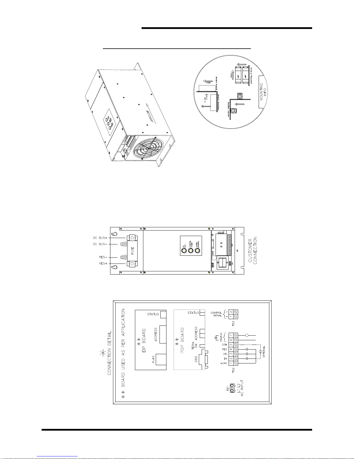
Figure 6-2: M3452 K6 Chassis Dimensional Outline Drawing.................................................................55
Figure 6-3: M3452 K9 Chassis Dimensional Outline Drawing.................................................................56
Figure 6-4: M3452 K10 Chassis Dimensional Outline Drawing...............................................................57
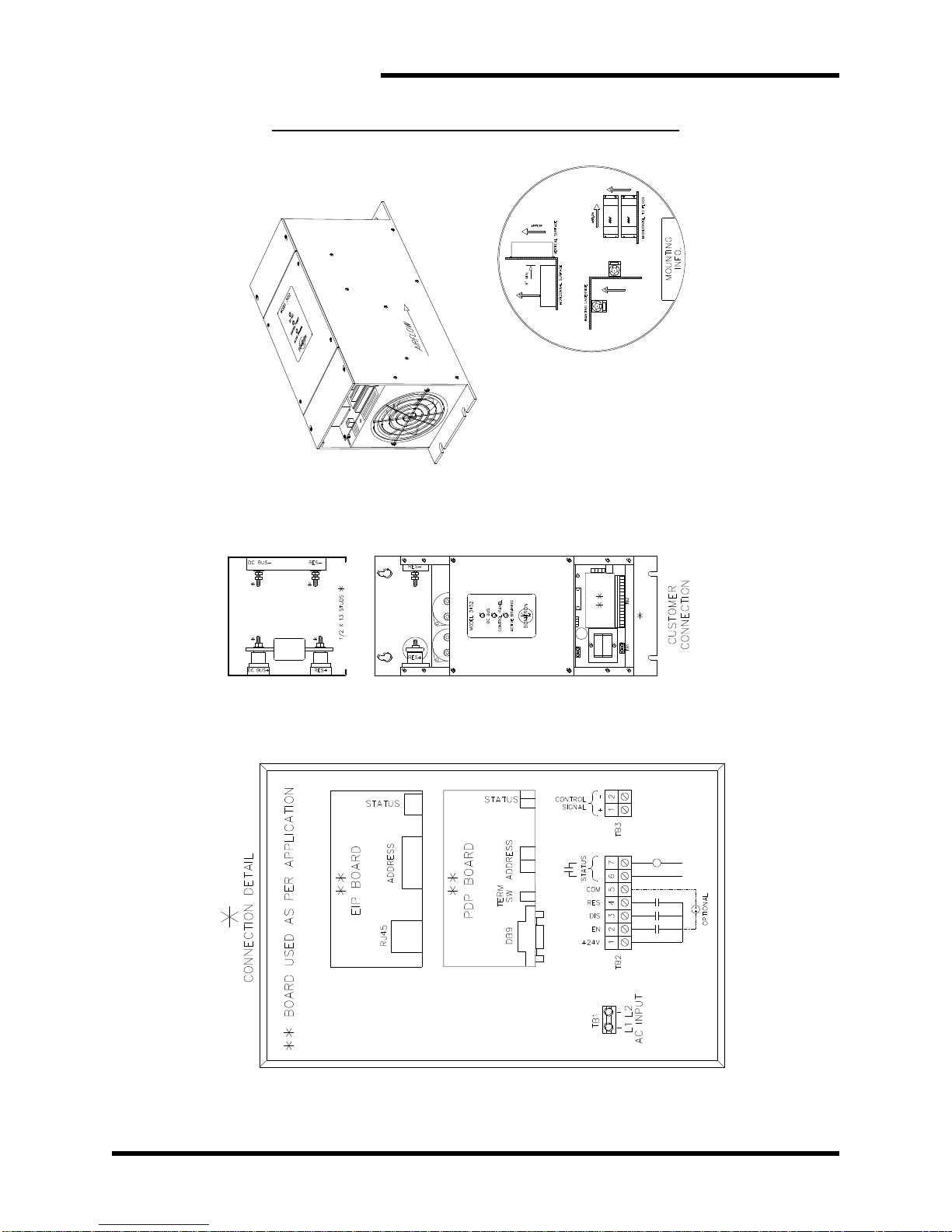
Figure 6-5: M3452 M14 Chassis Dimensional Outline Drawing ..............................................................58
Figure 6-6: M3452 T10 Chassis Dimensional Outline Drawing ...............................................................59

M3452 vR8 EIP/PDP
6
6.8. Block Diagrams..........................................................................................................................60
Figure 6-7: Block Diagram (All 200A thru 1200A and 1600A in T10 Chassis) .......................................60
Figure 6-8: Block Diagram (1600A in M14 Chassis)................................................................................60
7. APPENDICES.............................................................................................................................61
7.1. Application Notes....................................................................................................................... 61
7.1.1. Sizing Your Braking Requirements.........................................................................................61
7.1.2. Common Bus Application Note ..............................................................................................63
7.1.3. Bonitron Line Regeneration Modules .....................................................................................64

User’s Manual
7
1. INTRODUCTION
1.1. WHO SHOULD USE
This manual is intendedfor use by anyone who is responsible for integrating, installing,
maintaining, troubleshooting, or using this equipment with any AC drive system.
Please keep this manual for future reference.
1.2. PURPOSE AND SCOPE
This manual is a user’s guide for the Model M3452 dynamic braking transistor module.
It will provide the user with the necessary information to successfully install, integrate,
and use the M3452 dynamic braking transistor Module in a variable frequency AC
drive system.
In the event of any conflict between this document and any publication and/or
documentation related to the AC drive system, the latter shall have precedence.
1.3. MANUAL VERSION AND CHANGE RECORD
Application notes and indicator information were updated in Rev 01h.
Dimensional outlines and connection drawings were updated in Rev 02.
Link Length limits were updated in Rev 02a.
A correction was made in the Node Address Switches section in Rev 02b.
The T10 Chassis was added in Rev 02c.
Figure 3-5 was updated in Rev 02d.
Manual template was updated in Rev 02e.
Figure 6-5 was updated in Rev 02f.
Update to Section 4.2.6.1.4 in Rev 02g.
Update to Section 3.4 was made in Rev 02h.
Figure 1-1: Typical M3452 –R8
K9 CHASSIS
M14 CHASSIS

M3452 vR8 EIP/PDP
8
1.4. SYMBOL CONVENTIONS USED IN THIS MANUAL AND ON
EQUIPMENT
Earth Ground or Protective Earth
AC Voltage
DC Voltage
DANGER!
DANGER: Electrical hazard - Identifies a statement that indicates
a shock or electrocution hazard that must be avoided.
DANGER!
DANGER: Identifies information about practices or circumstances
that can lead to personal injury or death, property damage, or
economic loss.
CAUTION!
CAUTION: Identifies information about practices or circumstances
that can lead to property damage, or economic loss. Attentions
help you identify a potential hazard, avoid a hazard, and
recognize the consequences.
CAUTION!
CAUTION: Heat or burn hazard - Identifies a statement regarding
heat production or a burn hazard that should be avoided.

User’s Manual
9
2. PRODUCT DESCRIPTION
Bonitron M3452 heavy duty braking transistors are used with AC drives to allow full power
braking and eliminate overvoltage faults. This permits controlled braking and dramatically
shortens motor stopping time.
The M3452 works with variable frequency drives (with DC bus connections) to monitor the
DC bus. If overvoltage occurs, the M3452 shunts the excess energy through an external
braking resistor to prevent overvoltage faults.
During motor braking or deceleration, the frequency of an AC motor is higher than the
connected variable frequency drive. In this case, the motor acts as a generator. This
power returns to the DC bus of the drive, causing the voltage to rise. If this energy is not
controlled, the motor may run with high peak voltages, the energy may be dissipated as
heat in the motor, or the drive may trip on an over-voltage condition.
The R8 option allows for braking kit monitoring and control over a remote I/O network or
with discreteI/O. Extensive fault monitoring and chopper operation can becontrolled over
the network, and criticalfunctions can be controlled or monitored discretely. Master/Slave
operation can be changed on the fly for multiple-module systems to allow for redundancy
in the power sections for critical applications or quick reconfiguration. Remote
temperature monitoring can be used to allow for maximum production. Remote discharge
can also be used to bring the DC bus of a system down during shutdowns for quick
maintenance. Remote setpoint adjustment can be used to tailor braking thresholds for
energy efficiency and process control. Other parameters can also be monitored, including
bus voltage and duty cycle, along with a history of faults.
2.1. RELATED PRODUCTS
The M3452 series is one of several overvoltage solutions offered by Bonitron. Below
are a few related products, including braking resistors that are used in conjunction with
the M3452 series.
BRAKING TRANSISTORS
Like the M3452 heavy duty braking transistors, Bonitron M3575T and M3675T
standard duty braking transistors work with variable frequency drives (with DC
bus connections) to monitor the DC bus. If overvoltage occurs, the M3575T or
M3675T shunts the excess energy through an external braking resistor to
prevent overvoltage faults. The M3575T series is rated up to 600A peak / 20%
duty, while the M3675T series is rated up to 10A peak / 20% duty.
BRAKING RESISTORS
Bonitron offers resistor solutions to complement its braking transistor selection.
The M3575R series is rated up to 32 A peak / 20% duty, while the M3775R series
is rated up to 1600 A / 100% duty. Custom resistors are also available.
LINE REGENERATION
Bonitron is famous for its industry-leading line regeneration solutions. The
Bonitron M3645 line regen returns regenerative energy back onto the AC line
instead of dissipating theenergy as heat in aresistor, and isidealfor applications
with high duty cycles, frequent deceleration, or where heat from a resistor may
be an issue. The M3645 line regen features an interactive digital display with
event logging.

M3452 vR8 EIP/PDP
10
Please contact your AC drive distributor or visit our website at www.bonitron.com for
more information on these additional products.
2.2. PART NUMBER BREAKDOWN
Figure 2-1: M3452 Part Number Breakdown
BASE MODEL NUMBER
The base model number for all dynamic braking transistor modules is M3452.
CONTROL VOLTAGE RATING
The control voltage rating indicates the control voltage to the unit. This can be the
drive system AC line voltage or a different input voltage. This is indicated by a code
letter.
Note: Not all system voltages are available as control voltages.
Table 2-1: Control Voltage Rating
CONTROL VOLTAGE
RATING CODE
VOLTAGES
U
115 - 120VAC
L
230 - 240VAC
E
380 - 415VAC
H
460 - 480VAC
C
575 - 600VAC
BRAKING CURRENT RATING
The braking current rating indicates the maximum current level that can safely be
handled by the M3452 dynamic braking transistor module.
The braking current rating is indicated by a 3 or 4-digit number. For example, 300
indicates a braking current rating of 300 Amps maximum.
Table 2-2: Available Braking Current Ratings
AVAILABLE CURRENT RATINGS
(ADC)
200, 300, 600, 800, 1200, 1600
M3452
U
600
C
K6
-
R8PDP
BASE MODEL NUMBER
CONTROL VOLTAGE
BRAKING CURRENT
*DC BUS VOLTAGE
CHASSIS STYLE
CONTROL OPTION
-

User’s Manual
11
*DC BUS VOLTAGE
This code is used only if different from the control voltage rating.
Omit this position if control voltage is the same as nominal AC line voltage.
The DC bus voltage indicates the voltage regulation level of the DC bus if the control
voltage input does not correspond to the actual drive bus being controlled.
The DC bus voltage uses the codes L, E, H, C, and Y as shown in Table 2-3.
Table 2-3: DC Bus Voltage Rating
VOLTAGE
RATING CODE
VOLTAGES
(NOMINAL AC LINE /DC BUS TRIGGER LEVEL)
L
230 –240 VAC Line / 375 VDC
E
380 –415 VAC Line / 620 VDC
H
460 –480 VAC Line / 750 VDC
C
575 –600 VAC Line / 940 VDC
Y
690 VAC Line / 1090 VDC”
Nxxxx
Special (xxxx VDC)
Nxxxx is used only for custom trigger levels. Contact Bonitron before specifying
Nxxxx.
CHASSIS
The chassis code represents the chassis type and size of the dynamic braking
transistor module.
Table 2-4: Chassis Codes
CHASSIS
CODE
CURRENT
(AMPS)
TYPE
DIMENSIONS
(H”X W”X D”)
K6
200-600
Open Chassis
20.00 x 7.12 x 10.50
K9
800
Open Chassis
20.00 x 9.05 x 10.25
K10
1200
Open Chassis
20.00 x 10.00 x 10.50
M14
1600
Open Chassis
28.00 x 13.90 x 14.60
T10
1600
Open Chassis
30.60 x 10.12 x 19.20
CONTROL AND NETWORK OPTION
This code indicates the network protocol selected. See Table 2-5 below for a list of
available R8 options. Please contact Bonitron if you have any other special
requirements.
Table 2-5: Control Option Codes
CONTROL OPTION
CODE
DESCRIPTION
R8PDP
R8 unit with PROFIBUS comm module
R8EIP
R8 unit with EtherNet/IP comm module

M3452 vR8 EIP/PDP
12
2.3. GENERAL SPECIFICATIONS
Table 2-6: General Specifications
PARAMETER
SPECIFICATION
DC Bus Voltage
325 –1090 VDC
DC Braking Current
200 –1600 ADC
Control Voltage
Single Phase, 115, 230, 380, 460, 575 VAC
±10% 50/60 Hz 70 VA
Indicators
DC Bus
Control Power
Active Braking
Network I/O
Inputs
Outputs
Enable
DC Bus Discharge
Fault Reset
Master/Slave Select
Setpoint Adjust
Heat Sink Temperature
Bus Voltage
Fault State
Master/Slave Status
Fault Records
Logic I/O
Inputs –24V
Outputs –Max 140 VAC / 200 VDC at
100mA
Enable
Fault Reset
DC Bus Discharge
Ready Status
Control I/O
Sharing Control Signal
Operating Temp
0to 40C
Storage Temp
-20to 65C
Humidity
Below 90%, non-condensing
Atmosphere
Free of corrosive gas or conductive dust

User’s Manual
13
2.4. GENERAL PRECAUTIONS AND SAFETY WARNINGS
DANGER!
HIGH VOLTAGES MAY BE PRESENT!
NEVER ATTEMPT TO SERVICE THIS PRODUCT WITHOUT FIRST DISCONNECTING
FROM THE INCOMING AC POWER AND DC BUS.
ALWAYS ALLOW ADEQUATE TIME FOR RESIDUAL VOLTAGES TO DRAIN BEFORE
ATTEMPTING SERVICE.
BEFORE ATTEMPTING INSTALLATION OR REMOVAL OF THIS PRODUCT,BE SURE
TO REVIEW ALL AC DRIVE DOCUMENTATION FOR RELATED SAFETY
PRECAUTIONS.
INSTALLATION AND/OR REMOVAL OF THIS PRODUCT SHOULD ONLY BE DONE BY
A QUALIFIED ELECTRICIAN IN ACCORDANCE WITH NATIONAL ELECTRICAL
CODE OR EQUIVALENT REGULATIONS.
FAILURE TO HEED THESE WARNINGS MAY RESULT IN SERIOUS
BODILY INJURY OR DEATH.
CAUTION!
THIS PRODUCT WILL GENERATE HEAT DURING OPERATION.
THIS PRODUCT SHOULD BE INSTALLED ACCORDINGLY ON NON-FLAMMABLE
SURFACES WITH CLEARANCES OF AT LEAST TWO INCHES IN ALL DIRECTIONS.
ALWAYS ALLOW AMPLE TIME FOR THE UNIT TO COOL BEFORE ATTEMPTING
SERVICE ON THIS PRODUCT.
ALWAYS BE SURE THE BRAKING CAPACITY OF THE CHOPPER AND LOAD BANK
DOES NOT EXCEED THE CAPACITY OF THE CONNECTED DRIVE!
REVIEW THE APPLICATION NOTE IN SECTION 7OF THIS MANUAL FOR
INFORMATION ABUT COMMON DC BUS SYSTEMS.
Important Notice about Drives with DC Link Chokes!
DURING BRAKING SITUATIONS,ENERGY STORED IN A DRIVE’S DCLINK CHOKES
CAN CREATE EXTREME OVER-VOLTAGE CONDITIONS FOR DYNAMIC BRAKING
CONTROL MODULES.TO AVOID THESE CONDITIONS,DC CONNECTIONS FROM
RESISTIVE BRAKING CONTROL MODULES TO THE DRIVE SYSTEM MUST ALWAYS
BE MADE DIRECTLY IN PARALLEL WITH THE DRIVE’S FILTER CAPACITORS.
THESE MODULES SHOULD NEVER BE CONNECTED IN SERIES WITH A DRIVE’S
DC LINK CHOKES.
BE SURE TO REVIEW THE RELEVENT AC DRIVE DOCUMENTATION TO ENSURE
THAT THE PROPER CONNECTIONS ARE USED.
CONTACT THE DRIVE MANUFACTURER OR EQUIPMENT SUPPLIER FOR
ASSISTANCE WITH DRIVE CONNECTIONS.
ANY QUESTIONS RELATING TO APPLICATION, INSTALLATION, OR SERVICE
SAFETY SHOULD BE DIRECTED TO THE EQUIPMENT SUPPLIER.

M3452 vR8 EIP/PDP
14
This page intentionally left blank

User’s Manual
15
3. INSTALLATION INSTRUCTIONS
DANGER!
Installation and/or removal of this product should only be performed by a qualified
electrician in accordance with National Electrical Code or local codes and
regulations.
Proper installation of the model M3452 dynamic brake module should be done following
the steps outlined below. Be sure to refer to all other relevant system documentation as
these steps are performed. Please direct all installation inquiries that may arise during the
installation and start-up of this product to the equipment supplier or system integrator.
3.1. PRODUCT INSPECTION
Upon receipt of this product, please verify that the product received matches the
product that was ordered and that there is no physical damage to the unit. If the wrong
product was received or the product is damaged in any way, please contact the
supplier from which the product was purchased.
3.2. SITE SELECTION
The installation site for the module should be chosen with several considerations in
mind:
All units require adequate protection from the elements.
Adequate clearance should be allowed for easy access to terminals and
adjustments. This will facilitate inspection and maintenance.
Sufficient circulation of clean, dry air should be provided. Ambient temperatures
should not exceed +40°C (+104°F) nor be less than 0°C (+32°F) and non-
condensing. Ambient air should not be contaminated with harmful chemicalvapors
or excessive dust, dirt, or moisture.
The unit will require a minimum clearance of six (6) inches above and below it to
allow for proper airflow for cooling. Avoid mounting the unit with its air intake near
heat sources.
3.3. MOUNTING
Once the installation site has been selected as outlined above, and the mounting holes
drilled and mounting studs or anchors installed, the dynamic brake module is ready to
be hung in position. Be sure all mounting hardware is tightened securely.
Refer to Section 6.4 of this manual to determine the correct mounting dimensions and
provisions for the unit.

M3452 vR8 EIP/PDP
16
3.4. WIRING AND CUSTOMER CONNECTIONS
3.4.1. POWER WIRING
DANGER!
Only qualified electricians should perform and maintain the
interconnection wiring of this product. All wiring should be done in
accordance with local codes.
Wire size should be selected in accordance with local codes, accordingto the
current rating of the braking transistor. Use copper conductors rated 75°C.
In general, the wire type should be selected by the nominal system AC
voltage and the continuous current rating of the module.
Table 3-1: Power Wiring Specifications
CHASSIS
TERMINAL
CONNECTION
TORQUE
K6
DC+, DC-, RES+, RES-
3/8” stud
192 lb-in
K9
DC+, DC-, RES+, RES-
1/2" stud
360 lb-in
K10
DC+, DC-, RES+, RES-
1/2" stud
300 lb-in
M14
DC+, DC-, RES+, RES-
Bus Bar
N/A
T10
DC+, DC-, RES+, RES-
Bus Bar
N/A
3.4.1.1. DC BUS CONNECTION
As a general rule of thumb, 30 feet (10m) is the maximum total buswork
or cable that the chopper should be mounted from the drive. This means
that the actual installation distance should be 15 feet (5m), as the cable
must go out and back. If you must connect the choppers farther away,
see Section 6.6.
The braking transistor must be connected directly to the DC bus filter
capacitors of the drive.
Figure 3-10 is an example of the terminals that may be available in your
installation. Not all of the terminals may be on your drive. Refer to the
drive manufacturer's manual or technical documents to locate the proper
terminals. Your drive will have different terminal markings depending on
manufacturer and drive series.
Ensure that the polarity of the connection is correct. Incorrect polarity will
effectively short the DC bus of the drive, and can cause severe damage
to the drive, load resistor, and the Bonitron braking transistor.
The proper terminals to attach the braking transistor are marked + and -
on Figure 3-10.
The terminals marked BR+ and BR- are intended for the internal braking
transistor. If the Bonitron external braking transistor is hooked to the
terminals, the braking transistor will not operate properly. In some cases,
it may cause drive failure.
The terminals marked X and Y are intended for connection of a DC link
choke. If the Bonitron braking transistor is connected to the terminals
marked "X" and "-" in Figure 3-10, switching resonances caused by the
DC link choke will destroy the braking transistor. If the Bonitron braking
transistor is connected between X and Y, the drive will not operate.

User’s Manual
17
If the braking transistor is connected to the terminals marked "A" and "B"
in Figure 3-10, switching resonances caused by the lack of filter
capacitance during precharge will destroy the braking transistor.
3.4.1.2. RESISTOR CONNECTION
The polarity of the resistor connections is not important; however, it is
critical that the resistor be connected to the proper terminals. Improper
hookup can lead to the resistor being connected directly across the DC
bus, which will cause severe overheating and drive stress.
3.4.1.3. GROUNDING REQUIREMENTS
All units come equipped with either a ground terminal or ground stud that
is connected to the module chassis. Ground the chassis in accordance
with local codes. Typically, the wire gauge will be the same as is used to
ground the attached drive.
3.4.2. I/O WIRING
Table 3-2: I/O Terminal Block Specifications: R8 Control Board
TERMINAL
FUNCTION
ELECTRICAL
SPECIFICATIONS
MIN
WIRE
AWG
MAX
WIRE
AWG
TORQUE
TB1-1
Control Voltage
L1
120 VAC –0.6 A
230 VAC –0.3 A
460 VAC –0.16 A
575 V –0.15 A
16
10
4.5 lb-in
TB1-2
Control Voltage
L2
120 VAC –0.6 A
230 VAC –0.3 A
460 VAC –0.16 A
575 VAC –0.15 A
16
10
4.5 lb-in
TB2-1
V+ Input Supply
Max 50mA 24V supply for
inputs
18
12
4.5 lb-in
TB2-2
Enable Input
24 V, 10 mA
18
12
4.5 lb-in
TB2-3
Discharge Bus Input
24 V, 10 mA
18
12
4.5 lb-in
TB2-4
Reset
24 V, 10 mA
18
12
4.5 lb-in
TB2-5
Input Common Return
Max 100 mA, 24 VDC
18
12
4.5 lb-in
TB2-6&7
Status Output
110 VAC, 100 mA Max
18
12
4.5 lb-in
TB3-1&2
Master/Slave control signal
<50 VDC, 500 mA
18
12
4.5 lb-in

M3452 vR8 EIP/PDP
18
Figure 3-1: Customer Connections in K6 Chassis

User’s Manual
19
Figure 3-2: Customer Connections in K9 Chassis

M3452 vR8 EIP/PDP
20
Figure 3-3: Customer Connections in K10 Chassis
Other manuals for M3452
1
This manual suits for next models
57
Table of contents
Other bonitron Control Unit manuals

bonitron
bonitron M3528M2 User manual

bonitron
bonitron M3628PUD User manual

bonitron
bonitron M3699 User manual

bonitron
bonitron M3460RD User manual

bonitron
bonitron M3528M4 User manual

bonitron
bonitron M3575R User manual

bonitron
bonitron M3452 User manual

bonitron
bonitron M3460D User manual

bonitron
bonitron M3345D User manual

bonitron
bonitron M3452 EIP User manual