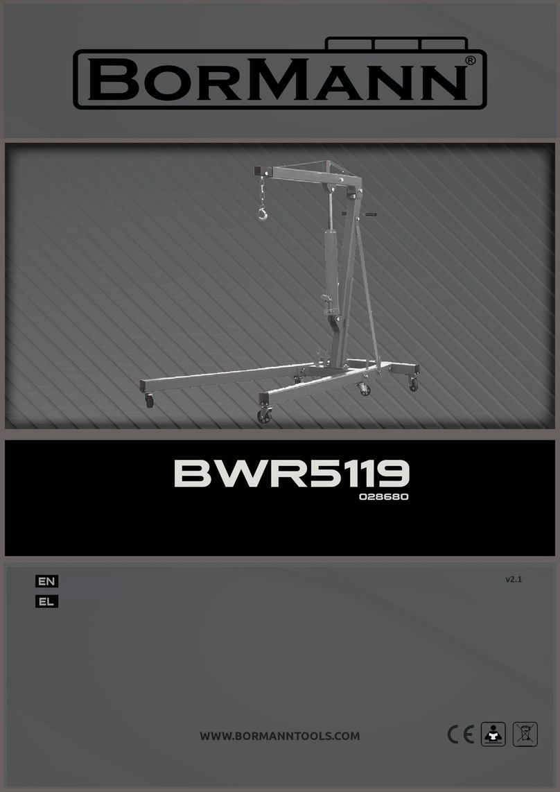
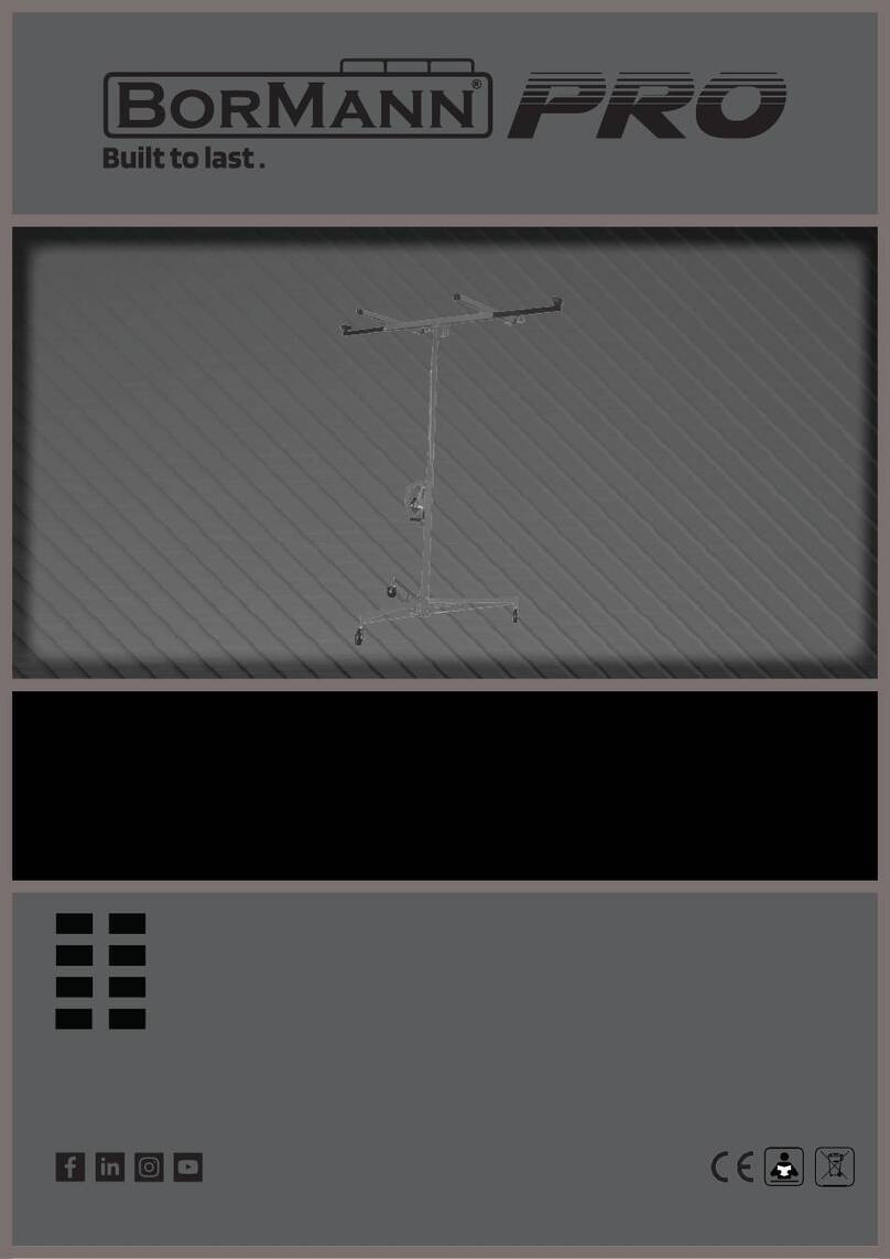
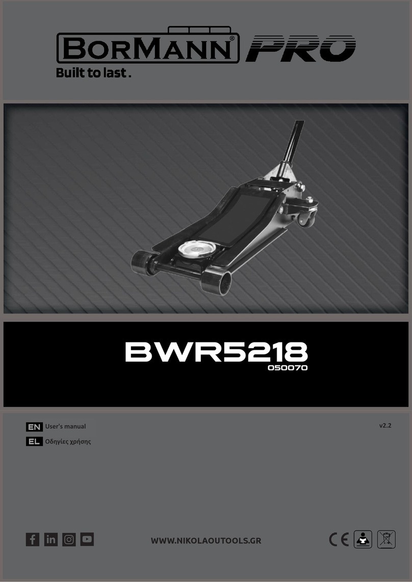
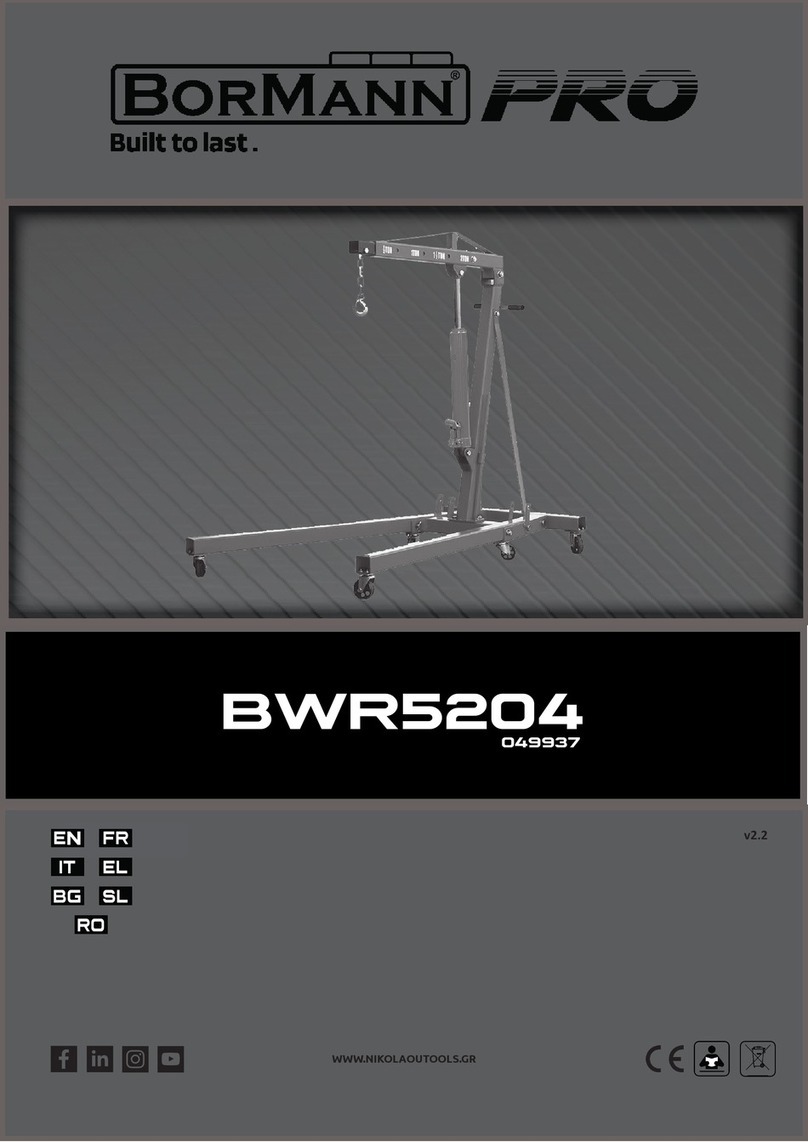
BorMann BWR5074 User manual

www.BormannTools.com
Οδηγίες χρήσης BWR5074

www.BormannTools.com
ΠΡΟΣΟΧΗ!
Διαβάστε τις οδηγίες ασφάλειας με προσοχή πριν χρησιμοποιήσετε το
συγκεκριμένο περονοφόρο.
Το συγκεκριμένο εγχειρίδιο περιέχει γενικές κατευθύνσεις και οδηγίες
και ο κατασκευαστής διατηρεί το δικαίωμα να αλλάξει χαρακτηριστικά
του προϊόντος και τον σχεδιασμό του χωρίς προηγουμένη ενημέρωση
του αγοραστή.
•Ο χρήστης πρέπει να διαβάσει όλες τις οδηγίες ασφάλειας και τις προειδοποιητικές
πινακίδες πριν προχωρήσει σε χρήση του.
•Μην χρησιμοποιήσετε το περονοφόρο αν δεν γνωρίζετε την χρήση του και αν δεν
έχετε εκπαιδευτεί στην χρήση του.
•Μην χρησιμοποιήσετε το περονοφόρο πριν ελέγξετε την ακεραιότητα του και την
κατάσταση του. Δώστε ιδιαίτερη προσοχή σε σημεία που φθείρονται πιο ευκολά
όπως είναι οι ροδές, οι λάβες, οι προστατευτικές διατάξεις και αλλά.
•Μην το χρησιμοποιήσετε σε έδαφος με κλίση.
•Μην χρησιμοποιείτε το περονοφόρο για την ανύψωση ανθρώπων.
•Ο χρήστης καλό θα ήταννα χρησιμοποιεί γάντια για τις σκληρές δουλείες και όταν
χρειάζεται να μεταφέρει βαριά αντικείμενα.
•Όταν έχετε τελειώσει την μεταφορά που θέλετε όλοι οι άνθρωποι θα πρέπει να
βρίσκονται σε απόσταση από τα πιρουνιά τουλάχιστον 600 mm.
•Μην προσπαθείτε να φορτώσετε το περονοφόρο με μεγαλύτερο βάρος από το
αναφερόμενο στην πινακίδα χαρακτηριστικών.
•Μην φορτώνετε μονόπαντα το περονοφόρο. Χρησιμοποιήστε και τα δυο πιρουνιά
για να φορτώσετε και κατανέμετε το βάρος και στα δυο πιρουνιά ισόποσα.
•Απαγορεύεται να παραμένουν άνθρωποι κάτω από το περονοφόρο.
•Όταν χρειάζεται να μεταφέρετε αντικείμενα με το περονοφόρο κρατήστε τα
πιρουνιά σε ύψος μικρότερο από τα 300mm
•Σε διαφορετική περίπτωση θα πρέπει να δείξετε μεγάλη προσοχή κατά την
μεταφορά.
Εμφάνιση προϊόντος και τεχνικά χαρακτηριστικά.
Τεχνικά χαρακτηριστικά και λειτουργία περονοφόρου.
Το συγκεκριμένο περονοφόρο αποτελείται από ένα υδραυλικό σύστημα ανύψωσης
φορτίων και ένα πλαίσιο.
Το περονοφόρο χρησιμοποιεί ένα υδραυλικό γρύλλο γιανα ανυψώνει φορτία στο
επιθυμητό ύψος τα οποία μπορούν να μεταφερθούν όπως σε ένα απλό παλετοφόρο
χειροκίνητα. Το υδραυλικό σύστημα είναι εφοδιασμένο με μια βαλβίδα ελέγχου λαδιού για
την ομαλή ανύψωση και καταβίβαση φορτίων. Το πλαίσιο του περονοφόρου είναι ποιοτικά
συγκολλημένο με καλής ποιότητας ατσάλι για μακροχρόνια χρήση. Οι ροδές εδράζονται
πάνω σε ρουλεμάν για την ελεύθερη κύλιση τους και είναι από πλαστικό καλής ποιότητας
ώστε να μην φθείρει ακόμα και το πιο μαλακά δάπεδα. Οι πίσω ροδές είναι εφοδιασμένες
και με φρένο για το όσο το δυνατόν πιο ασφαλή ανύψωση του φορτιού.
Όταν θέλετε να ανυψώσετε φορτία φρενάρετε τις πίσω ροδές και εισάγετε τα πιρουνιά
κάτω από την παλέτα που θέλετε να ανυψώσετε. Πρεσάρετε χρησιμοποιώντας τον λεβιέ.

www.BormannTools.com
Χρησιμοποιώντας υδραυλική πίεση το πιστόνι ανεβαίνει και με την βοήθεια μιας διάταξης
με αλυσίδα τα πιρουνιά ανεβαίνουν και ανυψώνουν την παλέτα.
Η παλέτα με το φορτίο έχει τώρα την δυνατότητα να μετακινηθεί τραβώντας το
περονοφόρο από τον λεβιέ.
Για να κατεβάσετε την παλέτα απλά χρησιμοποιήστε τον λεβιέ τραβώντας τον προς τα
πάνω.
Συνθήκες λειτουργίας.
1. Θερμοκρασία λειτουργίας
-25℃~+40℃.
2. Σχετική υγρασία κάτω από
90%
3. Το περονοφόρο μπορεί να
λειτουργήσει σε περιβάλλον
χωρίς βροχή και χωρίς
παρουσία διαβρωτικών
αέριων.
4. Χρήση σε εσωτερικό χώρο με
επίπεδο και σταθερό έδαφος.
Χρήση και συντήρηση
1. Το λαδί του περονοφόρου
πρέπει να φιλτράρεται και να
παραμένει αρκετό μέσα στο
περονοφόρο ώστε να
διατηρείτε η σωστή του
λειτουργία.
2. Πριν την χρήση Ελέγξτε ότι
το περονοφόρο είναι σε καλή
κατάσταση και ότι δεν
υπάρχουν χαλαρά εξαρτήματα
πουθενά.
3. Το φορτίο πρέπει να είναι ισόποσα μοιρασμένο πάνω στα πιρουνιά και κοντά στο
κέντρο βάρους.
4. Μόλις ολοκληρώσετε την μεταφορά ή την ανύψωση μην αφήνετε βάρος πάνω στα
πιρουνιά του περονοφόρου.
5. Όταν καταβιβάζετε φορτία προχωράτε με αργές κινήσεις και μην βιάζεστε να
κατεβεί η παλέτα κάτω καθώς αυτό θα έχει σαν αποτέλεσμα την πρόωρη φθορά
της βαλβίδας του περονοφόρου και εγκυμονεί κίνδυνους για την σταθερότητα του
και την ασφάλεια σας.
6. Τα φρένα στους πίσω τροχούς είναι εγκατεστημένα για λόγους ασφάλειας. Όταν
ανυψώνετε φορτία κρατήστε τα φρένα πατημένα ώστε να μην μετακινηθεί το
περονοφόρο.
Χειροκίνητο περονοφόρο Bormann
Μοντέλο
BWR5074
Μέγιστο φορτιο
Q(kg)
1000
Κέντρο βάρους
c(mm)
500
Βάρος περονοφόρου
kg
316
Ύψος περονοφόρου
h1(mm)
2080
Ύψος ανύψωσης
h
3
(mm)
3000
Συνολικό ύψος
h
4
(mm)
3080
Ύψος πιρουνιών στην
κάτω θέση h13(mm) 90/75
Συνολικό Μήκος
l
1
(mm)
1280
Συνολικόφάρδος
b
1
(mm)
700/980
Διαστάσεις πιρουνιών
s/e/l(mm)
60*142*1100
Πλάτος πιρουνιών
b
5
(mm)
550
Ακτίνα στροφής
Wa(mm)
1200
Ταχύτητα ανύψωσης με
φορτίο και χωρίςmm/stroke 9.5/10.5
Ταχύτητα καταβίβασης mm/s
Χειροκίνητος
έλεγχος

www.BormannTools.com
No.
Βλάβη
Αίτιο
Λύση
1 Το ύψος ανύψωσης
είναι περιορισμένο
Μη επαρκής ποσότητα
λαδιού
Για να προσθέσετε λαδί στο περονοφόρο
ξεσφίξτε την βίδα ,και γεμίστε με καθαρό
φρέσκο λαδί μέχρι την οπή συμπλήρωσης.
Σφίξτε ξανά την βίδα.
2
Τα πιρουνιά δεν
ανεβαίνουν
πρεσάροντας λαδί
1.Η πυκνότητα του λαδιού
είναι λάθος
Αλλάξτε τα λαδιά με καινούργια καθαρά
λαδιά
2.Υπαρχουν ξένα σώματα
μέσα στο λαδί που
εμποδίζουν την κυκλοφορία
του στον κύλινδρο
Φιλτράρετε το λαδί που βρίσκετε μέσα στο
περονοφόρο ή αλλάξτε τα λαδιά.
3.Η βαλβίδα ανακούφισης, ο
λεβιές χειρισμού και το
ελατήριο επαναφοράς δεν
λειτουργούν, δεν είναι στην
χαμηλότερη θέση ή έχουν
κολλήσει από ξένα σώματα.
Εξετάστε το ελατήριο να δείτε ότι βρίσκετε σε
λειτουργική κατάσταση ρυθμίστε τον λεβιέ
επαναφοράς στην χαμηλότερη κλειστή θέση
και αφαιρέστε τυχόν ξένα σωματίδια.
4
.
H θέση του λεβιέ δεν είναι
σωστά ρυθμισμένη. Επαναρυθμίστε τον λεβιέ.
3
Μετάαπό ανύψωση
τα πιρουνιά δεν
κατεβαίνουν
1
.
η θέση του λεβιέ δεν
είναι σωστά ρυθμισμένη. 1. Επαναρυθμίστε τον λεβιέ.
2. Έχει παραμορφωθεί το
πιστόνι από υπερβολικό
φορτίο
2.Αποσυναρμολογηστε και προχωρήστε σε
αντικατάσταση
3
.
το πλαίσιο που κινούνται
τα πιρουνιά έχει
παραμορφωθεί
3. Αποσυναρμολογήστε και προχωρήστε σε
αντικατάσταση
4 Διαρροή λαδιού
Η στεγανοποίηση διάφορων
μερών έχει φθαρεί ή
καταστραφεί
Κάποια μέρη του
περονοφόρου έχουν σπάσει
ή χαλάσει
Αντικαταστήστε με καινούργια γνησιά
ανταλλακτικά

www.BormannTools.com
Attentions:
Please read the instructions carefully before using this manual hydraulic stacker.
This manual is general-purpose specification, and we reserve the rights of the
manual hydraulic stacker technology improving. If the manual and material have
discrepancies, in kind prevail. Thanks for your understanding.
Warning
Pay attention to the following matters before operating this stacker:
1. SDA manual hydraulic stacker can only be operated indoor on level and
solid ground and it is strictly prohibited to operate this stacker in a corrosive
environment with acid and alkali.
2.Please read this manual carefully and understand the performance of this
stacker before operating; Inspection of the stacker should be conducted carefully
every time before operation to ensure that the stacker is in normal condition. It is
strictly prohibited to operate a stacker with trouble.
3.It is strictly prohibited to operate the stacker when overloaded. The load
capacity and the load center should meet the requirements in the parameter table of
this manual.
4.When SDA stacker is used for piling, the gravity center of the goods must
be within the two forks and it is strictly prohibited to pile bulk goods.
5.When it is required to transport the goods for a comparatively long distance,
the height of the forks from the ground should not exceed 0.5m.
6.When piling goods, it is strictly prohibited for people to stand under the forks
or around the stacker.
7.It is strictly prohibited to stand on the forks for operation.

www.BormannTools.com
8.When the goods are on high level, the goods should be pushed forward or
pulled backward slowly and no cornering is allowed in such a case.
1. Product appearance and technical parameters
SDA Manual hydraulic stacker
Model No.
SDA1030
Capacity
Q
(
kg
)1000
Load center
C
(
mm
)500
Service weight
kg
316
Lowered mast
height
h1
(
mm)2080
Lifting height
h3
(
mm)3000
Overall height
h4
(
mm)3080
Fork lowered
height
h13
(
mm)90/75
Overall length
l1
(
kg
)1280
Overall width
b1
(
kg
)700/980
Fork size
s/e/l
(
mm)Fixed forks 60×142×1100 and
60×142×900
Fork width
b5
550/840/930
Ground
Clearancem1 25
Turning radius
Wa
(
mm)1200
Lifting speed
with/without
load
mm/
stroke 9.5/10.5
Falling speed
with/without
load mm/s Hand control

www.BormannTools.com
2. Structural characteristics
SDA manual hydraulic stacker consists of a hydraulic system and a door frame.
The stacker uses a manual hydraulic jack (hydraulic device) as force to lift
heavy goods, which are pushed, pulled and handled manually. The hydraulic device
is equipped with an oil return valve and the fork decline speed is controlled via a
hand lever to make the operation of the hydraulic system correct, safe and reliable.
The door frame is welded with high quality section steel such as to good rigidity and
high strength. Universal wheels with braking device are adopted as the back wheels,
which can rotate freely, easily and flexibly. Both front and back wheels are installed
on wheel shafts with ball bearings so as to rotate flexibly. Wear-resistant and durable
Nylon wheels are adopted so that it is not easy to damage the operation ground.
When lifting goods, insert the forks under the pallet of the goods, when
necessary, brake the back wheels and pull the hand lever. The pinch wheel presses
the pump core to make the oil in the pump cylinder flow into the piston cylinder, in
order to push the piston rod move upward and lift the forks upward via a chain for a
two times travel. Pull the hand lever back and forth so as to lift the goods and
achieve the purpose of lifting. When the forks are lifted to the maximum height, the
pressurized oil flows back into the oil tank via an oil draining hole and in that case,
even the hand lever is pulled, the forks rise no more to avoid damaging components
by impacting the top.
When handling heavy goods, the stacker is able to travel via manual pushing
(pulling).

www.BormannTools.com
When unloading, pull the unloading hand lever, the oil return valve opens and
with the effect of the dead weight of the heavy goods and forks, the operational oil in
the piston cylinder flows back into the oil tank through the oil return valve, and when
the piston rod and the forks decline to the lowest position, the goods are unloaded
and the forks are withdrawn.
3. Operation conditions
The operation of SDA manual hydraulic stacker should meet following conditions:
1.Ambient temperature for operation:-25℃~+40℃.
2.The relative humidity of the environment should be less than 90%RH.
3.The stacker can only operate in an environment without rain and harmful gas
erosion.
4.The stacker can only operate indoor on level and solid ground.
4. Operation and maintenance
1. The oil must be filtered and clean and ensure sufficient oil quantity.
2. Before operation, inspection must be conducted for the stacker to ensure
the stacker is in normal condition and there is no loose component.
3.The goods should be smoothly distributed on the forks and no overload is
allowed.
4.After the operation is completed, the heavy goods should be unloaded and
the heavy goods are not allowed to be on the forks for a long time.
5.When lowering goods, the hand lever of the oil return valve should be
operated slowly and gently to avoid sudden declination during quick declination
process which causes unsafe situation. When lowering the goods quickly, the oil
return valve must not be closed suddenly as inertial acceleration is generated during
the process of quick declination. If that, a great force will be generated to damage the
components and goods.

www.BormannTools.com
6.Raise and pull outward the front part of the panel by hands, take off the
panel and then the stacker can be used as pallet transporting cart or pallet stacker.
7.The brakes on back wheels are installed for the purpose of safety in
operation process. When the forks are rising for lifting goods or is used as an
operation platform, the brakes should be stepped down with foot to prevent the
stacker from moving.
5. Possible failures in operation and trouble shooting
No.
Failure
Cause analysis
Trouble shooting
1
The lifting height
cannot meet the
design requirement. Insufficient operation oil
To fill oil into the oil cylinder, turn out the bolt,
fill in filtered and clean operation oil to the oil
inlet height and then tighten the bolt.
2 When the hand lever
is pulled, the forks do
not rise.
1
.
The viscosity of the operation oil is too
great or no operation oil has been filled in.
Replace or fill in operation oil according to the
oil quantity regulated.
2
.
There is foreign matter in operation oil,
which makes the oil inlet valve cannot be
tightly closed.
Filter out the foreign matter or replace
operation oil according to the stipulation.
3
.
The oil draining valve, unloading hand
lever and tension spring do snot work, are not
at the lowest position or stuck by other
foreign mater.
Examine the tension spring to see if it is
correct, adjust the unloading hand lever to the
lowest close position and remove foreign
mater.
4
.
The positions of the oil draining valve and
unloading hand lever have not been correctly
adjusted.
Readjust the unloading tension bar nut
position.
3 After being raised, the
forks do not decline
1
.
The lever plate or screw is not correctly
adjusted. Check and adjust lever plate and screw
2
.
Too much unbalanced loading caused
pump permanent deformation occurs. Replace pump
3
.
The fork carriage, roller or chain wheel is
stuck, mast deformed. Check and replace relative parts
4 Oil leakage
1
.
Damaged or failed seal washer.
Replace with new sealing washer, repair or
replace new components, repair and tighten.
2
.
There is slight crack or through hole in
individual component.
3. Loose thread connection or non-tightly
pressed sealing ring.

www.BormannTools.com
No.
Name
Qty
No.
Name
Qty
1
Blade Plate
1
9
Tube
1
2
Spring
1
10
Pull Pole
1
3
Pin 4×32
1
11*
Chain
1
4
Roller
1
12
Shaft
1
5
Pin 4×20
1
13
Bolt
1
6
Pin 6×32
1
14
Nut M5
1
7
Pin 4×20
1
8
Hanle Knob
1

www.BormannTools.com
No.
Name
Qty
No.
Name
Qty
1*
Pump Plunger 18
1
15
Nut M8
1
2
Cap
1
16
Foot Pedal
1
3*
Dust Ring 18
1
17*
Rubber Cover
1
4*
Seal Ring 18
1
18
Pedal Frame
1
5
Spring
1
19
Bolt M8
×
40
1
6
Press plate
1
20
Bush 20
×
23
×
10
2
7*
3-hole shaft 20
×
105
1
21
Valve Washer
1
8
Pin 5
×
28
2
22
Valve
1
9
Pull Spring 2.5
×
16
×
180 1 23
Valve Spring 1
×
6
×
23.5 1
10*
Bush 20
×
23
×
11.5
2
24
Seal Washer 10
2
11
Shaft 12
×
45
1
25
Screw M10
×
1
2
12*
Bush12
×
14
×
20
1
26
Screw M16
×
1.5
1
13*
Roller 26
×
14
×
22
1
27
Seal Washer 16
1
14 Shaft Spring Ring 12 2 28
Valve Spring 0.5
×
4.8
×
21 1

www.BormannTools.com

www.BormannTools.com
No.
Name
Qty
No.
Name
Qty
29
Strike Pin
1
42
Seal Washer 20
1
30
Valve M16
×
1.5
1
43
Pin Seat
1
31
O Ring 10.6
×
1.8
1
44*
O Ring 8
×
2.65
1
32
Steel Ball 7
1
45
Lever Plate
1
33
Shaft 8
×
56
1
46
Screw M6
×
20
1
34
Axle Spring Ring 8
2
47
Nut M6
1
35
Steel Ball 5
1
48*
O Ring 7.5
×
2.65
1
36
Ball Seat
1
49
Screw M8
×
1
1
37
Spring 2
×
8
×
16
1
50
Piston 32/35/40
×
L
1
38 Screw M10×1 1 51
Piston Pipe 32/35/40
×L 1
39
O Ring 6.9
×
1.8
1
52
Seal Ring 32/35/40
1
40 Strike pin 1 53*
O Ring 32/35/40
×
3.55 1
41
Spring 1.2
×
10
×
22
1
54*
Dust Ring 32/35/40
1

www.BormannTools.com
No.
Name
Qty
No.
Name
Qty
2
Cap
1
17*
Rubber Cover
2
3*
Dust Ring 18
1
18
Pedal Frame
1
4*
Seal Ring 18
1
19
Bolt M8
×
40
1
5
Spring
1
20
Bush 20
×
23
×
10
2
6
Press plate
1
21
Valve Washer
1
7*
3-hole shaft 20
×
105
1
22
Valve
1
8
Pin 5
×
28
2
23
Valve Spring 1
×
6
×
23.5
1
9
Pull Spring 2.5
×
16
×
180 1 24 Seal Washer 10 2
10*
Bush 20
×
23
×
11.5
2
25
Screw M10
×
1
2
11
Shaft 12
×
45
1
26
Screw M16
×
1.5
1
12*
Bush12
×
14
×
20
1
27
Seal Washer 16
1
13* Roller 26×14×22 1 28
Valve Spring 0.5
×
4.8
×
21 1
14
Shaft Spring Ring 12
1
29
Strike Pin
1
15
Nut M8
1
30
Valve M16
×
1.5
1
16
Foot Pedal
1
31
O Ring 10.6
×
1.8
1
32
Steel Ball 7
1

www.BormannTools.com
No.
Name
Qty
No.
Name
Qty
33
Shaft 8
×
56
1
47
Nut M6
1
34
Axle Spring Ring 8
2
48*
O Ring 7.5
×
2.65
1
35
Steel Ball 5
1
49
Screw M8
×
1
1
36
Ball Seat
1
50
Piston 32/35/40
×
L
1
37
Spring 2
×
8
×
16
1
51
Piston Pipe 32/35/40
×
L
1
38
Screw M10
×
1
1
52
Seal Ring 32/35/40
1
39
O Ring 6.9
×
1.8
1
53*
O Ring 32/35/40
×
3.55
1
40
Strike pin
1
54*
Dust Ring 32/35/40
1
41
Spring 1.2
×
10
×
22
1
56
Washer 34.5
×
29
×
1.5
1
42
Seal Washer 20
1
57
Washer 28
×
20.5
×
3
1

www.BormannTools.com
43 Pin Seat 1 58*
Double Speed Piston 18
×
28
×
97 1
44*
O Ring 8
×
2.65
1
59
Pin 4
×
25
1
45
Lever Plate
1
60
Double Speed Barrel
1
46
Screw M6
×
20
1
61
Washer
1
No.
Name
Qty
No.
Name
Qty
1
Screw M16
×
50
4
7*
Slide Wheel 86.5
4
2
Steel Ball
Φ
19
4
Slide Wheel 106
4
3
Fixed forks welding
1
Slide Wheel 102
4
Adjustable forks welding
8
Axle Spring Ring 35
4
4
Nut M10
2
9
Bolt M10
×
40
2
5
Hole Ring D72
4
10
Forks
2
6
Bearing 6207

www.BormannTools.com
No
. Name Qty No. Name Qty
1
Slide Carriage
1
7
Axle Spring Ring 35
4
2
Screw M16
×
50
4
8
Screw M6
×
16
1
3
Steel Ball
Φ
19
4
9
“L” Long Shaft
1
4
Hole Spring Ring 72
4
10
Forks
2
5*
Bearing 80207
4
6*
Slide Wheel 86.5 4
Slide Wheel 106
4
Slide Wheel 102
4

www.BormannTools.com
6.5、Left Caster with brake
No.
Name
Qty
No.
Name
Qty
1
Brake Pedal
1
12
Flat Washer 10
1
2
Axle Spring Ring D10
2
13
Spring
Φ
2
×
19.5
×
32
1
3
Shaft
Φ
10
×
65
1
14
Caster Frame
1
4
Axle Spring Ring D25
1
15
Bolt M10
×
30
1
5*
Bearing 60105
2
16
Flat Washer 12
1
6
Washer 45
×
25.5
×
5
1
17
Nut M12
1
7
Bearing 51205
1
18*
Bush 20.5×25×2.5
2
8
Washer 46.5
×
27
×
5
1
19*
Bearing 60204
2
9
Hole Spring Ring D47
1
20*
Wheel
Φ
180
×
50
1

www.BormannTools.com
6.6、Right Caster
No.
Name
Qty
No.
Name
Qty
1
Dust Cover SBA-00062
1
10
Flat Washer 12
1
2
Alxe Spring Ring d25
1
11
Nut M12
1
3*
Bearing 60105
2
12
Bush 20.5×25×2.5
2
4
Washer 45×25.5×5
1
13*
Bearing 60204
2
5*
Bearing 51205
1
14*
Wheel
Φ
180×50
1
6
Washer 46.5×27×5
1
15
Bush 12×20×55
1
7
Hole Spring Ring D50
1
8
Caster Frame
1
9
Bolt M12×95
1

www.BormannTools.com
6.7、Chain Wheel
No.
Name
Qty
No.
Name
Qty
1
Chain wheel shaft (single
mast)
1
4
Chain Wheel
2
Chain wheel shaft (double
mast)
1
5
A Axle Spring Ring d30
2
2
A Hole Spring Ring D62
2
3
Bearing 6206
2
6.8、Chain
No.
Name
Qty
No.
Name
Qty
1
Nut M16
4
5
Shaft
Φ
5
2
2
Chain puller M16
×
1.5
1
6
Chain LH0846
1
3
Pin 2.5
×
25
4
7
Chain puller M16
×
1.5
1
4*
Pin 2
×
16
4
Other manuals for BWR5074
1
This manual suits for next models
1
Table of contents
Other BorMann Lifting System manuals

BorMann
BorMann PRO BWR5516 User manual

BorMann
BorMann BWR5218 User manual

BorMann
BorMann PRO BWR5204 User manual

BorMann
BorMann PRO BWR5140 User manual

BorMann
BorMann BWR5137 User manual

BorMann
BorMann BPA4012 User manual

BorMann
BorMann PRO BWR5202 User manual

BorMann
BorMann PRO BTC6200 User manual
BorMann
BorMann PRO BWR5203 User manual

BorMann
BorMann BWR5119 Parts list manual