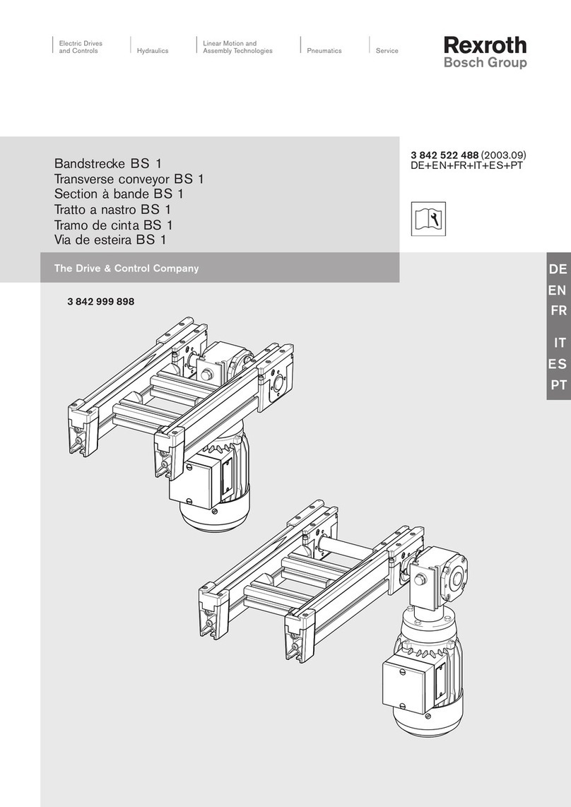
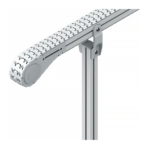
Bosch Rexroth BS 1/M User manual

de
en
fr
it
es
pt
MGEBosch Rexroth AG 1
BS 1/M (3 842 999 900)
Tecnica di montaggio
Técnica de montaje
Técnica de montagem
Montagetechnik
Construction technolog
Technique de montage
Bandstrecke BS 1/M
Transverse conveyor
Section à bande
Tratto a nastro
Tramo de cinta
ia de esteira

MGE Bosch Rexroth AG2
y
Die Installation, Inbetriebnahme, War-
tung und Instandsetzung, darf nur un-
ter Berücksichtigung aller Sicherheits-
hinweise und -Vorschriften und nur
durch geschultes, eingewiesenes
Fach ersonal durchgeführt werden!
Alle Sicherheitsabdeckungen, die bei
Wartungsarbeiten entfernt wurden,
müssen vor der Inbetriebnahme wie-
der angebracht werden!
Elektrische Anschlüsse nach der ent-
s rechenden nationalen Vorschrift.
Für Deutschland: VDE-Vorschrift VDE
0100!
Vor allen Instandsetzungs-, und
Wartungsarbeiten sind die Energiezu-
führungen (Hau tschalter, Druck-
minderventil etc.) abzuschalten!
Außerdem sind Massnahmen erforder-
lich, um ein unbeabsichtigtes Wieder-
einschalten zu verhindern,
z. B. am Hau tschalter ein ents re-
chendes Warnschild "Wartungs-
arbeiten", "Instandsetzungsarbeiten"
etc. anbringen!
Die BS 1/M ist nur für Werkstück-
trans orte im Transfersystem TS 1 mit
Bosch-Werkstückträgern WT 1 aus-
gelegt.
Haftung:
Bei Schäden, die aus nicht bestim-
mungsgemässer Verwendung und aus
eigenmächtigen, in dieser Anleitung
nicht vorgesehenen Eingriffen entste-
hen, erlischt jeglicher Gewähr-
leistungs- und Haftungsans ruch ge-
genüber dem Hersteller.
Garantie:
Bei Nichtverwendung von Originaler-
satzteilen erlischt der Garantiean-
s ruch!
TS 1-Ersatzteilliste-Nr.:
3 842 526 720.
Umweltschutz:
Beim Austausch von Schadteilen ist
auf eine sachgerechte Entsorgung
achten!
yy
Installation, initial o eration,
maintenance and re air work may only
be carried out in accordance with the
relevant safety instructions and
regulations and only by qualified and
s ecially trained ersonnel!
All security coverings that have
been removed during re air works
have to be reinstalled before
comissioning!
All electrical connections must be
made in accordance with the
a licable national regulations. For
Germany: regulation VDE 0100 (VDE,
German Association of Electricians)!
The current must always be switched
off (at main switch, ressure relief
valve etc.) before maintenance and
re air work!
Take recautions to revent
inadvertent restoration of ower, e.g.
by hanging a suitable warning sign at
the main switch, such as:
"Maintenance work in rogress",
or "Re air work in rogress"!
The BS 1/M is only designed for the
trans ort of work iece allets in
the TS 1 transfer system with Bosch
WT 1 work iece allets.
Liability:
In no event can the manufacturer
acce t warranty claims or liability
claims for damages arising from
im ro er use of the a liance or from
intervention in the a liance other
than that described in this instruction
manual.
Guarantee:
The manufacturer can acce t no
guarantee claims if non-original s are
arts have been used!
TS 1 s are arts list no.:
3 842 526 720.
Environmental rotection:
Always dis ose of damaged arts
in the correct manner when
re lacement work is com lete!
yyy
L'installation, la mise en service, la
maintenance et les ré arations ne
euvent être effectuées que ar des
ersonnes agréées et com étentes et
en res ectant les conseils de
sécurité !
Avant la mise en service, remettre en
lace tous les carters de sûreté
enlevés our les travaux de
maintenance !
Les branchements électriques doivent
être conformes à la réglementation
nationale.
Pour l'Allemagne : norme VDE 0100 !
Avant d'effectuer des ré arations
ou des travaux de maintenance, cou er
l'alimentation en énergie (interru teur
rinci al, mano-détendeur etc.) !
D'autre art, rendre toutes les
mesures nécessaires our éviter une
remise en marche accidentelle, en
a osant ar exem le rès de
l'interru teur rinci al un anneau
d'avertissement "travaux de
maintenance", "ré arations" etc. !
Le convoyeur transversal électrique
BS 1/M n'a été conçu que our le
trans ort de ièces dans le système
de transfert TS 1 avec les alettes
orte- ièces WT 1 de Bosch.
Res onsabilité :
le fabricant décline toute
res onsabilité et exclut toute
réclamation concernant les
dommages dus à une utilisation
non conforme ou suite à des
modifications effectuées sans
autorisation et non révues ci-contre.
Garantie :
En cas de non-utilisation des ièces
détachées d'origine, le constructeur
exclut toute res onsabilité !
N° de référence de la liste des ièces
détachées TS 1 : 3 842 52 6 720.
Protection de l'environnement :
Veiller à ce que les ièces
endommagées soient éliminées en
toute conformité !
Sicherheitshinweise!
Safety instructions!
Conseils de sécurité !
de
en
fr
it
es
pt
MGEBosch Rexroth AG 3
Fig. 1
1
4x
M5x16
A5,3-FST
2
”A”
”A”
yyy
Fig. 1
1 BS 1/M, rêt au montage
avec sûreté "A" !
2 Moto-réducteur et matériel de
fixation inclus.
yy
Fig.1
1 BS 1/M, ready to install
with trans ort retainer "A"!
2 Gear motor with fastening material
included.
y
Fig. 1
1 BS 1/M, montagefertig
mit Trans ortsicherung "A"!
2 Getriebemotor mit Befestigungs-
material beigelegt.
Anlieferzustand/Lieferumfang BS 1/M
Delivery condition/Scope of delivery
État à la livraison/Fournitures

MGE Bosch Rexroth AG4
Fig. 2 Fig. 3
SZ 1
M6
M6x12
3 842 523 4314x
y
Befestigungssatz Fig. 2:
Für den Einbau der BS 1/M zwischen
Strecken ST 1:
Stützen SZ 1
(Fig. 3).
Auswahl und Bestell-Nrn. siehe TS 1-
Katalog.
yyy
Kit de fixation Fig. 2 :
Pour le montage de la BS 1/M entre
des sections ST 1.
Supports SZ 1
(Fig. 3).
Assortiment et numéros de référence,
consulter le catalogue TS 1.
yy
Fastening sets Fig. 2:
For installation of BS 1/M between
conveyor sections ST 1:
Leg sets SZ 1
(Fig. 3).
For selection and ordernumbers see
TS 1 catalogue.
Zubehör
Accessories
Accessoires

de
en
fr
it
es
pt
MGEBosch Rexroth AG 5
Fig. 4
27 109,5 27
30
75
ca. 295
b - 44
b + 28
b + 2
b + 30
Hauptabmessungen/Funktionsmaße
Main dimensions/Functional dimensions
Mesures principales/Dimensions fonctionnelles
Motoranbau innen Fig. 4
Motor mounting, inner Fig. 4
Montage intérieur du moteur Fig. 4

MGE Bosch Rexroth AG6
27 109,5 27
30
75
ca. 295
110
180
b - 44
b +2
b + 28
b + 30
Fig. 5
Motoranbau außen Fig. 5
Motor mounting, outer Fig. 5
Montage extérieur du moteur Fig. 5

de
en
fr
it
es
pt
MGEBosch Rexroth AG 7
Fig. 6
Fig. 7
”A”
2x 2x
”A”
2x 2x
A
B
C
y
Allgemeines
Das Befestigen der Baueinheit
BS 1/M im Transfersystem erfolgt
nach dem Hammerschrauben rinzi .
Dies bewirkt eine kraftschlüssige Be-
festigung in den Längsnuten der Profi-
le. Beim Festschrauben der
Sechskantmutter dreht sich der
Hammerschraubenko f um 90° in die
richtige S ann osition (Fig. 6), max.
Anzugsdrehmoment 10 Nm.
A = Einsatzlage
B = Klemmlage
C = Anlage in Nut
(Drehmomentstütze)
Trans ortsicherung ”A” erst nach dem
Einbau zwischen ST 1 oder nach der
Montage auf SZ 1 entfernen (Fig. 7)!
yyy
Généralités
La fixation du com osant BS 1/M
sur le système de transfert est
assurée suivant le rinci e de la vis à
tête rectangulaire. Ceci ermet une
fixation de force dans les rainures
longitudinales des rofilés. En vissant
à fond l'écrou hexagonal, la tête de la
vis à tête rectangulaire ivote de 90°
et se met dans la osition de serrage
correcte (Fig. 6), cou le de serrage
max. 10 Nm.
A = Position d'insertion
B = Position de serrage
C = Position dans la rainure
(support du couple)
Enlever la sûreté de trans ort "A"
seulement a rès avoir monté la
section à bande entre les ST 1 ou sur
le SZ 1 (Fig. 7) !
yy
General
The BS 1/M unit is secured in the
transfer system using the T-bolt rinci-
le.
This creates a friction lock in the longi-
tudinal grooves of the rofiles. When
the hex nut is tightened, the T-bolt
head rotates 90° to the ro er fixing
osition (Fig. 6).
Max. torque 10 Nm.
A = Position on insertion
B = Clamping position
C = Arrangement in groove
(torque support)
Only remove trans ort retainer ”A” af-
ter installation between ST1 sets or
after mounting on SZ 1 (Fig. 7)!
Einbau in das Transfersystem
Installing in the transfer system
Montage dans le système de transfert
“A“ = Trans ortsicherung
“A“ = Trans ort retainer
“A“ = Sûreté de trans ort

MGE Bosch Rexroth AG8
Fig. 8
1
”X”
SW 8
(4x)
M6
M6x12
3 842 523 431
4x
2
SW 6
10 Nm
2
SW 6
10 Nm
y
Montagefolge Fig. 8:
1 Gelbe Schutzka e “X“ von
Motorwelle abziehen, Motor mit
Befestigungssatz am Getriebe-
flansch anschrauben, Nabe im
Getriebe ist werkseitig gefettet.
2 Befestigungssätze (3 842 523 431)
an BS 1/M montieren.
Fortsetzung Seite 9!
yyy
Procédure de montage Fig. 8 :
1 Enlever le ca uchon jaune de
rotection “X“ de l’arbre du moteur,
visser le moteur à l’aide du kit de
fixation sur la bride du réducteur, le
moyeu du réducteur est lubrifié en
usine.
2 Monter les kits de fixation
(3 842 523 431) sur la BS 1/M.
Suite age 9 !
yy
Sequence of assembly Fig. 8:
1 Remove yellow rotective ca “X“
from motor shaft, mount motor with
fastening set to gear flange, hub in
gear has already been greased in
the factory.
2 Mount fastening sets
(3 842 523 431) to BS 1/M.
Continued on age 9!
Einbau zwischen Strecken ST 1
Installation between conveyor sections ST 1
Montage entre les sections ST 1

de
en
fr
it
es
pt
MGEBosch Rexroth AG 9
ST 1 BS 1/M ST 1
SZ 1 SZ 1
l*)
3
SW 6
10 Nm
3
SW 6
10 Nm
Fig. 9
Einbau zwischen Strecken ST 1
Installation between conveyor sections ST 1
Montage entre les sections ST 1
y
3 BS 1/M von unten zwischen
beide ST 1 einheben und in den T-
Nuten befestigen (Fig. 9)
Der Einbau der BS 1/M in die Strecke
ST 1 muß aus Gründen der Funktions-
sicherheit und zur Verhinderung des
vorzeitigen Verschleißes nach Flucht
und Waage, rechtwinklig und
achs arallel durchgeführt werden!
yyy
3 Soulever la BS 1 ar en-dessous
entre les deux ST 1 et la fixer dans
les rainures en T (Fig. 9)
Pour des raisons de sécurité de
fonctionnement et our éviter toute
usure antici ée, lors du montage de la
BS 1/M sur une section ST 1, veiller à
ce que celle-ci soit alignée à la
verticale et à l'horizontale en angle
droit arallèlement à l'axe !
yy
3 Lift BS 1 between the two ST 1
sets from underneath and secure it
in the T-grooves (Fig. 9)
The BS 1/M must be installed in the
conveyor section ST 1 aligned and
level, at right angles and arallel to
the axis, for reasons of functional
safety and to revent remature wear!
*) Bei l ≥ 3000 sind mittig zwei Stützen SZ 1 vorzusehen!
*) When l ≥ 3000 two leg sets SZ 1 must be installed mid-length!
*) Lorsque l ≥ 3000, révoir deux su orts SZ 1 au milieu!

MGE Bosch Rexroth AG10
1
”X”
SW 8
(4x)
Fig. 10
y
Montagefolge Fig. 10:
1 Gelbe Schutzka e “X“ von Motor-
welle abziehen, Motor mit
Befestigungssatz am Getriebe-
flansch anschrauben.
Nabe im Getriebe ist werkseitig ge-
fettet!
Fortsetzung Seite 11!
yyy
Procédure de montage Fig. 10 :
1 Enlever le ca uchon jaune de
rotection “X“ de l’arbre du moteur,
visser le moteur avec le kit de
fixation sur la bride du réducteur.
Le moyeu du réducteur est lubrifié
en usine !
Suite age 11 !
yy
Sequence of assembly Fig. 10:
1 Remove yellow rotective ca “X“
from motor shaft, mount motor to
gear flange using fastening set.
Hub in gear has already been greas-
ed in the factory!
Continued on age 11!
Montage auf Stützen SZ 1
Mounting on leg sets SZ 1
Montage sur supports SZ 1

de
en
fr
it
es
pt
MGEBosch Rexroth AG 11
Fig. 11
y
2 BS 1/M auf SZ 1 montieren.
Die Bandstecke BS 1/M kann je nach
Bestellänge auf zwei bis vier Stützen
SZ 1 montiert werden. Die SZ 1 wer-
den jeweils unter die Quer-
verbinder montiert.
Montagebeis iel Fig. 11:
Streckenlänge l = 4000 mit drei Stüt-
zen SZ 1.
yyy
2 Monter le BS 1/M sur le SZ 1.
Suivant la longueur commandée, la
section à bande BS 1/M eut être
montée sur 2 à 4 su orts SZ 1. Les
SZ 1 sont montées sous les liaisons
transversales res ectives.
Exem le de montage Fig. 11 :
longueur de section. l = 4000 avec
trois su orts SZ 1.
yy
2 Mount BS 1/M on SZ 1.
Transverse conveyor BS 1 can be
mounted on between two and four leg
sets SZ 1, de ending on the length
ordered. Attach SZ 1 under the a -
ro riate cross-connectors.
Assembly exam le, Fig. 11:
section length l = 4000 with three leg
sets SZ 1.
Montage auf Stützen SZ 1
Mounting on leg sets SZ 1
Montage sur supports SZ 1

MGE Bosch Rexroth AG12
SW 19
SW 13
”A”
BS 1/M
SZ 1
SZ 1
SZ 1
Fig. 12
yyy
Aligner longitudinalement et
transversalement, our cela, régler les
vis sans fin des ieds articulés.
A rès l'alignement, bloquer avec
l'écrou hexagonal "A" (Fig. 12).
y
Längs und quer ausrichten, dazu
S indeln der Gelenkfüße ents re-
chend einstellen.
Nach dem Ausrichten mit Sechs-
kantmutter "A" kontern (Fig. 12).
yy
Align lengthways and widthways,
adjusting the s indles on the hinged
feet.
After aligning, counter with hex nut
"A" (Fig. 12).
Ausrichten
Alignment
Alignement

de
en
fr
it
es
pt
MGEBosch Rexroth AG 13
Fig. 13
SW 31
BS 1/M
SZ 1
SZ 1
SZ 1
SW 13
Montage Fundamentwinkelsatz/Bodendübel (Fig. 13)
Mounting foundation set/floor anchor (Fig. 13)
Montage jeu d'équerres de fondation/chevilles de fond(Fig. 13)
Ø8/65 tief
Ø8/65 dee
Ø8/65 rof.

MGE Bosch Rexroth AG14
y
Wird die Steuerung kundenseitig
durchgeführt, ist ein Not-Aus-Schalter
vorzusehen!
Unfallverhütungsvorschrift Berufsge-
nossenschaft 20.0 Stetigförderer,
VBG 10.
Motoranschluß nur durch
Fach ersonal!
VDE-Vorschrift VDE 0100.
yy
If the control system is installed by the
customer, an emergency-off switch
must be included!
Unfallverhütungsvorschrift Berufsge-
nossenschaft 20.0 Stetigförde- rer,
VBG 10. (German accident
revention regulations of the trade
coo erative association 20.0
continuous conveyors, VBG 10).
Have motor connected only by
qualified ersonnel!
Regulation VDE 0100 of German
Association of Electricians (VDE).
yyy
Si le système de contrôle est installé
ar le client, révoir un bouton d'arrêt
d'urgence !
Unfallverhütungsvorschrift
Berufsgenossenschaft 20.0
Stetigförderer, VBG 10. (Directives
nationales allemandes de révention
des
accidents 20.0, convoyeurs à
fonctionnement continu, VBG 10).
Raccordement du moteur
uniquement ar un ersonnel
qualifié ! Norme VDE 0100.
Installation BS 1/M
Installation of BS 1/M
Installation BS 1/M
Motoranschluss
Motor connection
Raccordement du moteur
yyy
Procéder au raccordement du moteur
conformément aux s écifications sur
la tension et le courant indiquées sur
la laque signalétique (Fig. 14), selon
Fig. 15 (Y) ou Fig. 16 (∆).
Pour éviter d'endommager le câble de
raccordement, il est indis ensable de
tourner le couvercle de la boîte de
connexions sur le moteur de telle
façon que le câble (A) vienne de la
direction du couvercle du ventilateur
(B), (Fig. 17).
y
Der Motoranschluss ist nach den An-
gaben des Ty schildes (Fig. 14) ent-
s rechend S annung und Strom,
nach Fig. 15 (Y) oder Fig. 16 (∆)
durchzuführen.
Um Beschädigungen am Anschluss-
kabel zu vermeiden, muss der Deckel
des Klemmenkasten am Motor so ge-
dreht werden, dass die Kabeleinführ-
ung (A) aus Richtung Lüfterhaube (B)
erfolgt (Fig. 17).
yy
The motor must be connected
according to Fig.15 (Y) or
Fig. 16 (∆), de ending on the voltage
and current s ecifications on the
name late (Fig. 14).
To avoid damage to the connection
cable, the cover of the terminal box on
the motor must be turned such that
the cable can be inserted (A) from the
direction of the fan housing (B)
(Fig. 17).

de
en
fr
it
es
pt
MGEBosch Rexroth AG 15
Fig. 17
Fig. 16
Fig. 14
”A” (PG 9)
X
”B”
Fig. 15
Ty schild (Beis iel)
Name late (exam le)
Plaque signalétique (exem le)
Ansicht X
View X
Vue X

MGE Bosch Rexroth AG16
yyy
Déconnecter l'alimentation en énergie
(interru teur rinci al etc.) avant
d'entre rendre les
travaux de maintenance !
En outre, rendre les mesures
nécessaires our éviter une remise en
marche accidentelle, lacer
. ex. un anneau d'avertissement
rès de l'interru teur rinci al !
Tous les aliers sont ourvus d’un
graissage à vie et sont, sous
a lications normales, exem t
d’entretien dans la mesure où rien
d’autre n’est indiqué.
Lors de l’utilisation de substances
dissolvant les graisses sur le système,
ar ex. our des buts de nettoyage, un
contrôle régulier est toutefois
nécessaire et, le cas échéant, un
regraissage uniquement avec un
lubrifiant sans acide et exem t de
résine ( ar ex. « gleitmo 585K ») doit
être réalisé !
Réducteur (1, Fig. 18)
Le réducteur ne demande as
d'entretien !
Moteur (2, Fig. 18)
Pour garantir un refroidissement
suffisant, il est indis ensable de
nettoyer régulièrement les saletés et
la oussière qui se sont dé osés sur
le ca ot du moteur, dans les orifices
d’as iration du couvercle du
ventilateur et dans les es aces entre
les ailettes de refroidissement en
fonction des conditions ambiantes
données.
yy
Prior to maintenance work, disconnect
energy sources (main switch, etc.)!
In addition, take recautions to
revent inadvertent restoration of
ower, e.g., lace a warning sign
at the main switch!
All bearings are rovided with lifelong
lubrication and are maintenance free
under normal conditions, if not
otherwise indicated.
However, if grease-dissolving
substances are a lied to the system,
e.g. for cleaning ur oses, a regular
check should be made, and, if
necessary, the bearings should be
relubricated with acid and resin free
lubricant only (e.g. “gleitmo 585K”)!
Gear (1, Fig. 18)
The gear is maintenance-free!
Motor (2, Fig. 18)
To ensure adequate cooling, dirt and
dust must be removed from the motor
surface, the inlets of the fan housing,
and the interior surfaces of the cooling
fins on a regular basis, de ending on
environmental and o erating
conditions.
y
Vor Wartungsarbeiten sind die
Energiezuführungen (Hau tschalter
etc.) abzuschalten!
Außerdem sind Maßnahmen erforder-
lich um unbeabsichtigtes Wiederein-
schalten zu verhindern,
z. B. Warnschild am Hau tschalter
anbringen!
Alle Lagerstellen sind mit einer
Lebensdauerschmierung versehen
und unter normalen Anwendungen
wartungsfrei, sofern nicht anders an-
gegeben.
Beim Einsatz von fettlösenden Sub-
stanzen auf dem System, z.B. für
Reinigungszwecke, ist jedoch eine re-
gelmäßige Kontrolle und ggf. eine
Nachschmierung nur mit säure- und
harzfreiem Schmierstoff (z.B. „gleitmo
585K“) erforderlich!
Getriebe (1, Fig. 18)
Das Getriebe ist wartungsfrei!
Motor (2, Fig. 18)
Um eine ausreichende Kühlung
sicherzustellen, müssen Schmutz- und
Staubablagerungen an der Obe-
rfläche des Motors, den Ansaug-
öffnungen der Lüfterhaube und an den
Zwischenräumen der Kühlri en, den
Umgebungs-und Einsatzbedingungen
ents rechend, regelmäßig entfernt
werden.
Wartung
Maintenance
Maintenance

de
en
fr
it
es
pt
MGEBosch Rexroth AG 17
Fig. 18
1
2
3
yyy
Températures de surface !
Les surfaces des moteurs et engre-
nages soumises à certaines condi-
tions de charge et de service, euvent
atteindre des tem ératures
su érieures à 60 degrés Celsius.
Dans ce cas, il est im ératif de
s'en tenir aux instructions sur la
révention des accidents en vigueur
en renant des mesures adéquates
(en installant des dis ositifs de
rotection) ou en a osant des
anneaux d'avertissement !
Courroies dentées (3, Fig. 18)
Effectuer des contrôles réguliers
en vérifiant surtout à l'oeil nu si les
oints de soudure ne commencent
as à s'user. Contrôler le sens de
marche (dans le sens de la flèche) !
Lubrifier le cas échéant la courroie
dentée avec huile minérale, viscosité
68 d’a rès DIN ( . ex. Aral, Shell).
yy
Surface Temperatures!
The surfaces of motors and gears can
reach tem eratures of over 60
degrees Celsius under s ecific load
and o erating conditions.
In such situations the a licable rules
for accident revention must be
fulfilled with the necessary safety
warning signs or constructive
measures (safety devices).
Toothed belt (3, Fig. 18)
Conduct visual ins ections regularly
for wear, in articular at the welded
joint. Check trans ort direction (in
direction of arrow)!
Oil the toothed belt again if necessary
with mineral oil,
viscosity 68 according to DIN (e. g.
Aral, Shell).
y
Oberflächentemperaturen!
Die Oberflächen von Motoren und
Getrieben können unter bestimmten
Last-und Betriebsbedingungen Tem-
eraturen von mehr als 60 Grad Cel-
sius annehmen.
In diesen Fällen müssen durch ent-
s rechende konstruktive Maßnahmen
(Schutzvorrichtungen) oder ents re-
chende Sicherheitkennzeichnungs-
warnzeichen, die jeweils geltenden
Unfallverhütungsvorschriften (UVV) er-
füllt werden!
Zahnriemen (3, Fig. 18)
Regelmäßige Sichtkontrolle, insbeson-
dere der Schweißstelle auf Verschleiß.
Laufrichtung (in Pfeilrichtung) kontrol-
lieren!
Bei Bedarf Zahnriemen nachölen mit:
Mineralöl Viskostät 68 nach DIN (z. B.
Aral, Shell).

MGE Bosch Rexroth AG18
SW 3
2
6
3
7
4
5
4
5
7
6
8
4
5
4
5
SW 3 1
2x 4
Fig. 19
Instandsetzung BS 1/M
Repair BS 1/M
Réparations BS 1/M

de
en
fr
it
es
pt
MGEBosch Rexroth AG 19
yy
Prior to any re air work, disconnect
energy sources (main switch, etc.)!
In addition, take recautions to
revent inadvertent restoration of
ower, e. g., lace a warning sign
at the main switch!
If the BS 1/M is removed from section
ST 1 for maintenance work, a
trans ort retainer (see Fig. 7) must be
attached!
Changing toothed belt
motor mounting, inner Fig. 19:
1 Loosen the 2 x 4 screws at the drive
unit.
2 Lift the entire drive unit u wards,
keeping it level. Do not tilt!
3 Remove the toothed belt sideways.
4 Loosen the 2 x 2 screws on the
return ends.
5 Pull off belt guide u wards.
6 Remove toothed belt from roller.
7 Remove belt guide rofile GP 1.
8 Remove faulty toothed belt.
Install new toothed belt in reverse
order.
Please note:
When installing the return rollers ay
attention to the osition of the discs.
For the direction of movement of the
toothed belt, the arrow (welded joint)
must oint towards the drive unit!
Check that the new toothed belt is
oiled and if necessary, oil it with
mineral oil viscosity 68 according to
DIN (e. g. Aral, Shell)
Installing the drive unit:
Lower steadily into the subframe,
taking care to keep it level and
ensure that the toothed belt sits in
the gear teeth of the toothed belt
wheel!
Tighten 2 x 4 fastening screws
alternately and diagonally!
yyy
Débrancher l'alimentation en
énergie (interru teur rinci al etc.)
avant d'entre rendre tous travaux de
ré aration ! En outre, rendre les
mesures nécessaires our
éviter une remise en marche
accidentelle, lacer . ex. un
anneau d'avertissement rès
de l'interru teur rinci al !
Si, endant des travaux de
maintenance, la BS 1/M est démontée
de la section ST 1, mettre une sûreté
de trans ort (voir Fig. 7) !
Changement de la courroi dentée,
montage intérieur du moteur Fig. 19 :
1 Desserrer 2 x 4 vis sur l’unité d’en-
traînement.
2 Ôter l'ensemble de l'unité
d'entraînement en tirant vers le haut
en évitant de le déformer
et de l'accrocher !
3 Enlever la courroie dentée ar le
côté.
4 Desserrer res ectivement 2 x 2 vis
côté renvoi.
5 Tirer le guidage de courroies vers le
haut.
6 Retirer la courroie dentée du
rouleau.
7 Enlever le rofilé guide de courroie
GP 1.
8 Enlever la courroie dentée qui
est endommagée.
Pour installer une nouvelle courroie
dentée, suivre les instructions don-
nées ci-dessus dans l'ordre inverse.
Attention :
Lors du montage des oulies de
renvoi, tenir com te de la osition des
disques.
Sens de la marche de la courroie
dentée : la flèche ( oint de soudure)
doit montrer dans la direction de
l'unité d'entraînement !
Vérifier si la nouvelle courroie dentée
a été lubrifiée, le cas échéant la
lubrifier avec de l´huile minérale,
viscosité 68 d’a rès DIN ( . ex. Aral,
Shell).
Pour installer l'unité d'entraîne- ment
: la mettre bien droite dans la artie
inférieure en veillant à ne pas la
coincer et à ce que la courroie
dentée soit bien mise dans la
denture de la roue dentée !
Serrer 2 x 4 vis de fixation en
alternance et en "croisé" !
y
Vor allen Instandsetzungsarbeiten
Energiezuführungen (Hau tschalter
etc.) abschalten! Außerdem sind Maß-
nahmen erforderlich, um ein unbeab-
sichtigtes Wiedereinschalten zu ver-
hindern, z. B. Warnschild am
Hau tschalter anbringen!
Wird die BS 1/M zu den Instand-
setzungsarbeiten aus der Strecke
ST 1 ausgebaut, ist eine Trans ort-
sicherung (s. Fig. 7) anzubringen!
Zahnriemenwechsel
Motoranbau innen Fig. 19:
1 2 x 4 Schrauben an der Antriebs-
einheit lösen.
2 Kom lette Antriebseinheit gleich-
mäßig nach oben entnehmen, dabei
nicht verkanten!
3 Zahnriemen seitlich abnehmen.
4 je 2 x 2 Schrauben an den Umlenk-
seiten lösen.
5 Riemenführung nach oben abzie-
hen.
6 Zahnriemen von den Rollen abneh-
men.
7 Gurtführungs rofil GP 1 abnehmen.
8 Defekten Zahnriemen entfernen.
Einbau des neuen Zahnriemens in um-
gekehrter Reihenfolge.
Dabei ist zu beachten:
Bei Einbau der Umlenkrollen auf Lage
der Scheiben achten.
Laufrichtung des Zahnriemens Pfeil-
richtung (Schweißstelle) muß in Rich-
tung Antriebseinheit zeigen!
Prüfen ob der neue Zahnriemen geölt
ist, ggf. nachölen mit: Mineralöl
Viskostät 68 nach DIN (z. B. Aral,
Shell).
Einsetzen der Antriebseinheit:
Gleichmässig in Unterteile einsetzen,
dabei nicht verkanten und darauf
achten, dass der Zahnriemen in der
erzahnung des Zahnriemenrades
sitzt!
2 x 4 Befestigungsschrauben wech-
selseitig und "über Kreuz" anziehen!

MGE Bosch Rexroth AG20
y
Motoranbau außen Fig. 20:
1 2 x 4 Schrauben an der Antriebs-
einheit lösen.
2 Kom lette Antriebseinheit gleich-
mäßig nach oben entnehmen, dabei
nicht verkanten!
3 Sechskantwellenverbindung tren-
nen, dann Zahnriemen seitlich ab-
nehmen.
4 je 2 x 2 Schrauben an den Umlenk-
seiten lösen.
5 Riemenführung nach oben abziehen.
6 Zahnriemen von Rolle abnehmen.
7 Gurtführungs rofil GP 1 abnehmen.
8 Defekten Zahnriemen entfernen.
Einbau des neuen Zahnriemens in um-
gekehrter Reihenfolge.
Dabei ist zu beachten:
Bei Einbau der Umlenkrollen auf Lage
der Scheiben achten.
Laufrichtung des Zahnriemens Pfeil-
richtung (Schweißstelle) muß in Rich-
tung Antriebseinheit zeigen!
Prüfen ob der neue Zahnriemen geölt
ist, ggf. nachölen mit: Mineralöl
Viskostät 68 nach DIN (z. B. Aral,
Shell).
Einsetzen der Antriebseinheit:
Gleichmäßig in Unterteile einsetzen,
dabei nicht verkanten und darauf
achten, dass der Zahnriemen in der
erzahnung des Zahnriemenrades
sitzt!
2 x 4 Befestigungsschrauben wechs-
elseitig und "über Kreuz" anziehen!
yy
Motor mounting, outer Fig. 20:
1 Loosen the 2 x 4 screws at the drive
unit.
2 Lift the entire drive unit u wards,
kee ing it level. Do not tilt!
3 Disconnect hexagonshaft, then
remove toothed belt at the side.
4 Loosen the 2 x 2 screws at the
return ends.
5 Pull off belt guide u wards.
6 Remove toothed belt from roller.
7 Remove belt guide rofile GP 1.
8 Remove faulty toothed belt.
Install new toothed belt in reverse
order.
Please note:
When installing the return rollers ay
attention to the osition of the discs.
For the direction of movement of the
toothed belt, the arrow (welded joint)
must oint towards the drive unit!
Check that the new toothed belt is
oiled and if necessary, oil it with
mineral oil viscosity 68 according to
DIN (e.g. Aral, Shell)
Installing the drive unit:
Lower steadily into the subframe,
taking care to keep it level and
ensure that the toothed belt sits in
the gear teeth of the toothed belt
wheel!
Tighten 2 x 4 fastening screws
alternately and diagonally!
yyy
Montage extérieur du moteur
Fig. 20 :
1 Desserrer 2 x 4 vis de l’unité
d’entraînement.
2 Ôter l'ensemble de l'unité
d'entraînement en tirant vers le haut
en évitant de le déformer
et de l'accrocher !
3 Détacher l’arbre hexagonal, uis
enlever la courroie dentée ar le
côté.
4 Desserrer res ectivement 2 x 2 vis
côté renvoi.
5 Tirer le guidage de courroies vers le
haut.
6 Retirer la courroie dentée du
rouleau.
7 Enlever le rofilé guide de courroie
GP 1.
8 Enlever la courroie dentée
endommagée.
Pour installer une nouvelle courroie
dentée, suivre les instructions
données ci-dessus dans l'ordre
inverse. Attention :
Lors du montage des oulies de
renvoi, tenir com te de la osition des
disques.
Sens de marche de la courroie
dentée : la flèche ( oint de soudure)
doit montrer dans la direction de
l'unité d'entraînement !
Vérifier si la nouvelle courroie dentée
a été lubrifiée, le cas échéant la
lubrifier avec de l´huile minérale,
viscosité 68 d’a rès DIN ( . ex. Aral,
Shell).
Pour installer l'unité
d'entraînement : la mettre bien droite
dans la artie inférieure en veillant à
ne pas la coincer et à
ce que la courroie dentée soit bien
mise dans la denture de la roue
dentée !
Serrer 2 x 4 vis de fixation en
alternance et en "croisé" !
Zahnriemenwechsel
Changing toothed belt
Changement de la courroie dentée
Table of contents
Other Bosch Accessories manuals

Bosch
Bosch CISS User manual

Bosch
Bosch 1 270 020 900 User manual

Bosch
Bosch ISW-EN1247 User manual

Bosch
Bosch GWH 2400 ES NG User manual

Bosch
Bosch MSE-LZ User manual

Bosch
Bosch Rexroth ID 15 User manual

Bosch
Bosch ISC-PDL1-W18G User manual

Bosch
Bosch GHJ 12+18V Unisex User manual

Bosch
Bosch PSJ120S Assembly instructions

Bosch
Bosch ISC-CDL1-WA15G User manual

Bosch
Bosch Rexroth TS1 User manual

Bosch
Bosch ISC-PMC-S2S User manual

Bosch
Bosch PFB3060 User manual

Bosch
Bosch BGS6235GB User manual

Bosch
Bosch PLS User manual

Bosch
Bosch PLS User manual

Bosch
Bosch GPL 3 Professional User manual

Bosch
Bosch CleverMixx MSM1 IN Series User manual

Bosch
Bosch DS924i User manual

Bosch
Bosch IVAS 0273600075 User manual