manuals.online logo
Brands
  1. Home
  2. •
  3. Brands
  4. •
  5. Bosch
  6. •
  7. Accessories
  8. •
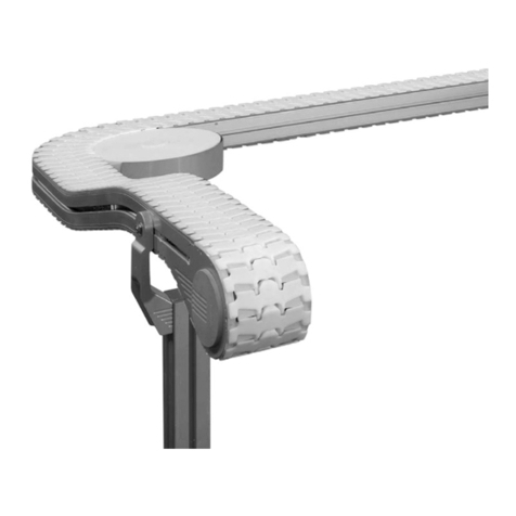
  9. Bosch Rexroth 3 842 547 200 User manual

Bosch Rexroth 3 842 547 200 User manual

3 842 547 200
554 148-01
4
2
1
3
2)
1)
3 842 554 148/2015-10
Replaces: –
DE+EN+FR+IT+ES
Montageanleitung • Assembly instructions • Instructions de montage
Istruzioni per il montaggio • Instrucciones de montaje
Sensoreinheit
Sensor unit
Unité de capteur
Unità sensore
Unidad de sensores
554148_2015_10.indd 1554148_2015_10.indd 1 09.10.2015 10:27:2109.10.2015 10:27:21
2/8Bosch Rexroth AG MPS | 3 842 554 148/2015-10
DE Sensoreinheit
Bitte beachten Sie:
Schalten Sie das Kistenhubgerät vor Montage und Installation der Sensoreinheit spannungsfrei (Stecker ziehen).
1) Siehe Seite 1: Montieren Sie die Sensoreinheit in der hinteren Nut, um eine mögliche Quetschgefahrenstelle zwischen
Anbauplatte und Sensoreinheit zu vermeiden.
2) Siehe Seite 1: Verlegen Sie das Kabel in einer Schlaufe in der Profilnut und sichern es mit dem beiliegenden
Abdeckprofil.
Funktion und Bedienen mit der Sensoreinheit siehe Betriebsanleitung 3 842 358 709 (www.boschrexroth.com/
medienverzeichnis), Bedienen mit Sensoreinheit.
Bedien- und Anzeigelemente
14
3
21: LED gelb – Schaltausgang aktiv
2: Potentiometer zum Einstellen der Empfindlichkeit
3: LED grün – Betrieb, Stabilitätsanzeige
4:fixiert auf „D“ (versiegelt)
Stabilitätsanzeige
Bei anliegender Versorgungsspannung und ausreichender Reflexion der Kiste leuchtet die grüne LED. Der Sensor
befindet sich in einem stabilen Schaltzustand.
stabiler Schaltzustand Schaltpunkt stabiler Schaltzustand
??
LED grün ein aus aus ein
LED gelb aus aus ein ein
Kiste da ?? KIste nicht da
Empfindlichkeit einstellen
Der Sensor ist voreingestellt, Sie können ihn ohne weitere Einstellung verwenden.
Ausnahmen:
• Bei dunklen, schlecht reflektierenden Kisten kann ein instabiler Schaltzustand auftreten (Kisten werden nicht
sicher erkannt). Erhöhen Sie die Empfindlichkeit.
Empfindlichkeit erhöhen: Schraube drehen nach +(im Uhrzeigersinn)
Empfindlichkeit verringern:Schraube drehen nach –(gegen Uhrzeigersinn)
fixiert auf „D“ (versiegelt), nicht verstellen
• Bei glänzenden, nicht parallel reflektierenden Kisten bringen Sie einen matten Aufkleber am Reflexionspunkt an.
Betrieb
Prüfen Sie, ob die Sensoreinheit sicher funktioniert:
• Bei anliegender Versorgungsspannung und ausreichender Reflexion der Kiste leuchtet die grüne LED.
• Wenn keine Kiste erkannt wird, leuchtet die gelbe LED.
Wartung, Instandsetzung, Entsorgung
• Halten Sie die Linsen der Sensoreinheit frei von Verschmutzungen.
• Verwenden Sie zur Reinigung ein weiches Tuch und ein sanftes Spülmittel,
keine Lösungsmittel oder Reiniger, die die Kunststoffteile beschädigen könnten.
• Entsorgen Sie die Sensoreinheit umweltgerecht gemäß den gültigen nationalen Bestimmungen
554148_2015_10.indd 2554148_2015_10.indd 2 09.10.2015 10:27:4109.10.2015 10:27:41
3 842 554 148/2015-10 | MPS Bosch Rexroth AG 3/8
EN Sensor unit
Please note:
Switch off the voltage to the case lifter before mounting and installing the sensor unit (pull the plug).
1) See page 1: Install the sensor unit in the rear slot in order to avoid a potentially dangerous crushing area between the
mounting plate and sensor unit.
2) See page 1: Lay the cable loop in the profile slot and secure it with the enclosed cover profile.
For setting and operating with the sensor unit and its functions, see operating instructions 3 842 358 709
(www.boschrexroth.com/mediadirectory), operating with the sensor unit.
Control and display elements
14
3
21: LED yellow—switch output active
2: Potentiometer for adjusting sensitivity
3: LED green—operation, stability display
4: Fixed to “D” (sealed)
Stability display
When supply voltage is present and reflection of the case is sufficient, the green LED lights up. The sensor is in a
stable switching status.
Stable switching status Switching point Stable switching status
??
LED green On Off Off On
LED yellow Off Off On On
Case present ?? Case not present
Set sensitivity
The sensor is pre-set; you can use it without further adjustment.
Exceptions:
• On dark, poorly reflective cases, an instable switching status can occur (cases are not reliably detected).
Increase the sensitivity.
Increase sensitivity: turn screw to +(clockwise)
Reduce sensitivity: turn screw to −(counterclockwise)
Fixed to “D” (sealed); do not adjust
• For shiny cases that do not reflect in parallel, attach a matte sticker to the reflection point.
Operation
Check whether the sensor unit is working safely:
• When supply voltage is present and reflection of the case is sufficient, the green LED lights up.
• If no case is detected, the yellow LED lights up.
Maintenance, repair, disposal
• Keep the lenses of the sensor unit free of contamination.
• For cleaning, use a soft cloth and a gentle dishwashing liquid; do not use solvents or cleansers that can damage
plastic parts.
• Dispose of the sensor unit in an environmentally responsible way in accordance with the applicable
national regulations.
554148_2015_10.indd 3554148_2015_10.indd 3 09.10.2015 10:27:4109.10.2015 10:27:41
4/8Bosch Rexroth AG MPS | 3 842 554 148/2015-10
FR Unité de capteur
Veuillez noter :
Mettez l'élévateur de caisses hors tension avant le montage et l'installation de l'unité de capteur (retirer le connecteur).
1) Voir page 1 : montez l'unité de capteur dans la rainure arrière pour éviter de créer une zone présentant un risque d'écrasement
entre la plaque de montage et l'unité de capteur.
2) Voir page 1 : placez le câble dans une boucle de la rainure de profilé et bloquez-le avec le profilé de protection fourni.
Pour plus d'informations sur le fonctionnement, le réglage et l'utilisation de l'unité de capteur, voir les instructions
de service 3 842 358 709 (www.boschrexroth.com/mediadirectory), Utilisation de l'unité de capteur.
Éléments de commande et d'affichage
14
3
21: LED jaune – Sortie de commutation active
2: Potentiomètre pour le réglage de la sensibilité
3: LED verte – Fonctionnement, affichage de la stabilité
4: Fixé sur « D » (bloqué)
Affichage de la stabilité
En présence de tension d'alimentation et d'une réflexion suffisante de la caisse, la LED s'allume en vert. Le capteur
se trouve dans un état de commutation stable.
état de commutation stable point de commutation état de commutation stable
??
LED verte on off off on
LED jaune off off on on
Caisse présente ?? Caisse non présente
Réglage de la sensibilité
Le capteur est préréglé, vous pouvez l'utiliser sans plus de réglage.
Exceptions :
• Avec des caisses sombres qui réfléchissent mal, l’état de commutation peut être instable (les caisses ne sont
pas détectées automatiquement). Augmentez la sensibilité.
Augmenter la sensibilité : tourner la vis vers le +(dans le sens des aiguilles d'une montre)
Diminuer la sensibilité : tourner la vis vers le –(dans le sens inverse des aiguilles d'une montre)
Fixé sur « D » (bloqué), ne pas modifier
• Si la caisse est brillante et ne réfléchit pas en parallèle, appliquez un autocollant mat sur le point de réflexion.
Fonctionnement
Contrôlez si l'unité de capteur fonctionne bien :
• En présence de tension d'alimentation et d'une réflexion suffisante de la caisse, la LED s'allume en vert.
• Si aucune caisse n’est détectée, la LED s’allume en jaune.
Maintenance, réparation, élimination
• Veillez à ce que les lentilles de l'unité de capteur soient toujours propres.
• Pour le nettoyage, utilisez un chiffon doux et un détergent non agressif, n’utilisez aucun solvant ou produit de
nettoyage susceptible d’endommager les pièces en plastique.
• Éliminez l'unité de capteur dans le respect de l'environnement, conformément aux dispositions nationales en vigueur
554148_2015_10.indd 4554148_2015_10.indd 4 09.10.2015 10:27:4209.10.2015 10:27:42
3 842 554 148/2015-10 | MPS Bosch Rexroth AG 5/8
IT Unità sensore
Osservare quanto segue:
Disinserire la tensione dall'apparecchio di sollevamento casse prima del montaggio e dell'installazione dell'unità
sensore (staccare la spina).
1) Vedi pagina 1: Montare l'unità sensore nella scanalatura posteriore per evitare un possibile punto di schiacciamento tra unità
sensore e piastra di ancoraggio.
2) Vedi pagina 1: Posare il cavo in un passante nella scanalatura di profilo e bloccarlo con il profilo di copertura incluso.
Per il funzionamento, la regolazione e l'azionamento dell’unità sensore vedi manuale di istruzioni 3 842 358 709
(www.boschrexroth.com/mediadirectory), Comando con unità sensore.
Elementi di azionamento e di visualizzazione
14
3
21: LED giallo – Uscita di spegnimento attiva
2: Potenziometro per la regolazione della sensibilità
3: LED verde – Esercizio, indicatore di stabilità
4:fissato su “D” (sigillato)
Indicatore di stabilità
Il LED verde si accende con la tensione di alimentazione presente e il riflesso sufficiente della cassa. Il sensore si
trova in uno stato stabile di spegnimento.
Stato stabile di spegnimento Punto di spegnimento Stato stabile di spegnimento
??
LED verde accesso spento spento accesso
LED giallo spento spento accesso accesso
Cassa presente ?? Cassa non presente
Impostazione sensibilità
Il sensore è preimpostato e si può utilizzare senza ulteriori impostazioni.
Eccezioni:
• In casse poco riflettenti e scure può verificarsi un stato di commutazione instabile (le casse non vengono
riconosciute come sicure). Aumentare la sensibilità.
Per aumentare la sensibilità: girare la vite verso +(in senso orario)
Per diminuire la sensibilità: girare la vite verso –(in senso antiorario)
fissato su “D” (sigillato), non regolare
• In casse lucide e che riflettono in modo non parallelo, collocare un adesivo opaco nel punto di riflesso.
Esercizio
Verificare se l'unità sensore funziona correttamente:
• Il LED verde si accende con la tensione di alimentazione presente e il riflesso sufficiente della cassa.
• Quando nessuna cassa viene riconosciuta, si accende il LED giallo.
Manutenzione, riparazione, smaltimento
• Mantenere le lenti dell'unità sensore pulite.
• Utilizzare un panno morbido e un detergente delicato per la pulizia: non utilizzare alcun solvente o detergente
che possa danneggiare le parti in plastica.
• Assicurarsi che l'unità sensore non comporti rischi per l'ambiente secondo le disposizioni nazionali vigenti
554148_2015_10.indd 5554148_2015_10.indd 5 09.10.2015 10:27:4209.10.2015 10:27:42
6/8Bosch Rexroth AG MPS | 3 842 554 148/2015-10
ES Unidad de sensores
Tenga en cuenta:
Desconecte la tensión del elevador de cajas antes del montaje y la instalación de la unidad de sensores
(desenchufar el conector).
1) Véase la página 1: Monte la unidad de sensores en la ranura trasera para evitar una posible zona de peligro de aplastamiento
entre la placa de instalación y la unidad de sensores.
2) Véase la página 1: Coloque el cable en un pasador y, a su vez, en la ranura de perfil y asegúrelo con el perfil de
cubrimiento adjunto.
Función, ajuste y manejo con la unidad de sensores, véase el manual de uso 3 842 358 709 (www.boschrexroth.com/
mediadirectory), manejo con unidad de sensores.
Elementos de manejo y señalización
14
3
21: LED amarillo – salida de conmutación activa
2: Potenciómetro para el ajuste de la sensibilidad
3: LED verde – funcionamiento, indicador de estabilidad
4:fijado en “D” (sellado)
Indicador de estabilidad
Si existe tensión de alimentación y una reflexión suficiente de la caja, se ilumina el LED verde. El sensor se
encuentra en un estado de conmutación estable.
Estado de conmutación estable Punto de conmutación Estado de conmutación estable
??
LED verde encendido apagado apagado encendido
LED amarillo apagado apagado encendido encendido
caja presente ?? caja no presente
Ajuste de la sensibilidad
El sensor está preajustado, por lo que puede utilizarlo sin necesidad de realizar ningún otro ajuste.
Excepciones:
• Con cajas oscuras con un mal reflejo, se puede producir un estado de conmutación inestable (las cajas no se
reconocen de forma segura). Aumente la sensibilidad.
Aumentar la sensibilidad: girar el tornillo hacia +(en sentido de las agujas del reloj)
Disminuir la sensibilidad: girar el tornillo hacia –(en sentido contrario a las agujas del reloj)
Fijado en “D” (sellado), no ajustar
• Con cajas brillantes con reflejos no paralelos, coloque un adhesivo mate en el punto de reflexión.
Funcionamiento
Compruebe si la unidad de sensores funciona de forma segura:
• Si existe tensión de alimentación y una reflexión suficiente de la caja, se ilumina el LED verde.
• Si no se reconoce ninguna caja, se ilumina el LED amarillo.
Mantenimiento, reparación, eliminación
• Mantenga las lentes de la unidad de sensores libres de suciedad.
• Para la limpieza, utilice un paño delicado y productos de limpieza suaves; no utilice disolventes o productos de
limpieza que puedan dañar las piezas de plástico.
• Elimine la unidad de sensores de forma respetuosa con el medioambiente conforme a la normativa vigente del país
554148_2015_10.indd 6554148_2015_10.indd 6 09.10.2015 10:27:4209.10.2015 10:27:42
3 842 554 148/2015-10 | MPS Bosch Rexroth AG 7/8
PT Unidade de sensores
Observe:
1) Consulte a página 1: Monte a unidade
de sensores na ranhura traseira para
evitar um possível ponto de perigo
de esmagamento entre a placa de
montagem e a unidade de sensores.
2) Consulte a página 1: Coloque o cabo
num nó corrediço na ranhura do perfil
e fixe-o com o perfil de cobertura
acompanhante.
Função, ajuste e operação com a
unidade de sensores, ver o manual de
operação 3 842 358 709
(www.boschrexroth.com/
mediadirectory), Operação com unidade
de sensores.
BG Сензор
Моля, обърнете внимание:
1) Вж. страница 1: Монтирайте
сензорната единица в задния канал,
за да се избегне зона на опасност
от премазване между монтажната
плоча и сензорната единица.
2) Вж. страница 1: Прекарайте кабела
през халката в профилния жлеб
и го подсигурете с прилежащия
покривен профил.
За функциониране, настройване
и опериране вж. ръководство за
експлоатация 3 842 358 711
(www.boschrexroth.com/
mediadirectory) Опериране със
сензорната единица.
CS Senzorická jednotka
Mějte prosím na zřeteli:
1) Viz strana 1: Senzorovou jednotku
namontujte do zadní drážky, aby
nedošlo ke vzniku místa s možným
rizikem zmáčknutí mezi montážní
deskou a senzorovou jednotkou.
2) Viz strana 1: Kabel proveďte okem v
profilové drážce a zajistěte jej pomocí
přiloženého krytu profilu.
Funkce, nastavení a obsluhování pomocí
jednotky senzoru viz návod k provozu
3 842 358 711 (www.boschrexroth.com/
mediadirectory), Ovládání se senzorovou
jednotkou.
DA Sensorenhed
Vær opmærksom på
følgende:
1) Se side 1: Montér sensorenheden
i den bageste not, så der ikke er
fare for at komme i klemme mellem
montagepladen og sensorenheden.
2) Se side 1: Før kablet i en løkke i
profilnoten, og sørg for at sikre det
med den vedlagte afdækningsprofil.
Vedr. funktion, indstilling og betjening
med sensorenheden, se driftsvejledning
3 842 358 711 (www.boschrexroth.
com/mediadirectory), Betjening med
sensorenhed.
ET Sensor
Palun pange tähele, et:
1) Vt lk 1: Paigaldage anduri üksus
tagumisele soonele, et vältida
ehitusplaadi ja anduri vahelist
võimalikku survekoha tekkimist.
2) Vt lk 1: Paigaldage kaabel aasana
profiilsoonde ja kindlustage see
juuresoleva katteprofiiliga.
Anduri üksuse funktsiooni, seadistamise
ja toimimise kohta vt kasutusjuhend
3 842 358 711 (www.boschrexroth.com/
mediadirectory), kasutage koos anduriga.
EL Μονάδα αισθητήρα
Προσοχή:
1) Βλέπε σελίδα 1: Συναρμολογήστε τη
μονάδα αισθητήρα στην πίσω εσοχή,
ώστε να αποτρέπεται ένα πιθανό
επικίνδυνο σημείο σύνθλιψης ανάμεσα
στην πλάκα προσάρτησης και στη
μονάδα του αισθητήρα.
2) Βλέπε σελίδα 1: Περάστε το καλώδιο
σε βρόχο μέσα στο προφίλ εσοχής
και ασφαλίστε το με το συνοδευτικό
καλυπτικό προφίλ.
Για τη λειτουργία, τη ρύθμιση και το
χειρισμό της μονάδας αισθητήρα βλέπε
βιβλίο χρήσης 3 842 358 711
(www.boschrexroth.com/
mediadirectory), χειρισμός με μονάδα
αισθητήρα.
FI Anturiyksikkö
Ota huomioon:
1) Katso sivu 1: Asenna tunnistinyksikkö
takimmaiseen uraan, jotta voit
välttää mahdollisen puristuksiin
jäämisen kohdan asennuslevyn ja
tunnistinyksikön välillä.
2) Katso sivu 1: Asenna kaapeli
silmukkana profiiliuraan ja varmista se
mukanatoimitetulla peiteprofiililla.
Toiminta, säätö ja käyttö
tunnistinyksikön kanssa, katso
käyttöohje 3 842 358 711 (www.
boschrexroth.com/mediadirectory),
Käyttö tunnistinyksikön kanssa.
GA Aonad braiteora
Tabhair faoi deara:
1) Féach leathanach 1: Déan an t-aonad
braiteora a fheistiú sa sliotán deiridh
chun spás ina bhféadfadh baol brúite
a bheith ann idir an pláta suiteála agus
an t-aonad braiteora a sheachaint.
2) Féach leathanach 1: Cuir síos an cábla
i lúb sa sliotán próifíle agus daingnigh
é leis an bpróifíl clúdaigh iniata.
Feidhmiú, socrú agus oibriú an aonad
braiteora féach an Treoir Oibriúcháin
3 842 358 713 (www.boschrexroth.
com/mediadirectory), Oibriú le haonad
braiteora.
HU Szenzoregység
Kérjük, vegye figyelembe az
alábbiakat:
1) Lásd az 1. oldalt: A szerelőlemez és
az érzékelőegység közötti becsípődés
veszélyének megelőzése érdekében
az érzékelőegységet a hátsó horonyba
szerelje.
2) Lásd az 1. oldalt: A kábelt fektesse
egy hurokban a profilhoronyba, majd
rögzítse a mellékelt takaróprofil
segítségével.
Az érzékelőegység működését,
beállítását és kezelését lásd a
3 842 358 713 számú üzemeltetési
útmutató (www.boschrexroth.
com/mediadirectory), Kezelés
érzékelőegységgel c. részében.
554148_2015_10.indd 7554148_2015_10.indd 7 09.10.2015 10:27:4309.10.2015 10:27:43
Bosch Rexroth AG
Postfach 30 02 07
70442 Stuttgart, Germany
Telefax +49 711 811–7777
www.boschrexroth.com
info@boschrexroth.de
8/8Bosch Rexroth AG MPS | 3 842 554 148/2015-10
Technische Änderungen vorbehalten
Subject to technical modifications
Sous réserve de modifications techniques
Soggetto a modifiche tecniche
Modificaciones técnicas reservadas
MT Unità tas-sensor
Nota:
1) Ara l-paġna 1: Arma l-unità tas-
sensur fil-gruv ta’ wara sabiex tevita
l-possibbiltà ta’ punt ta’ perikolu ta’
tgħaffiġ bejn il-pjanċa tal-immuntar u
l-unità tas-sensur.
2) Ara l-paġna 1: Qiegħed il-kejbil
f’ingassa fil-gruv tal-profil u pproteġih
bil-profil tal-kaver li jakkumpanjah.
Għal informazzjoni dwar il-funzjonament,
l-issettjar u l-operat bl-unità tas-
sensur, ara l-manwal tal-istruzzjonijiet
3 842 358 713 (www.boschrexroth.
com/mediadirectory), Operat bl-unità
tas-sensur.
NL Sensoreenheid
Let op a.u.b.:
1) Zie pagina 1: Monteer de
sensoreenheid in de achterste gleuf
om mogelijke gevarenzones voor
beknelling tussen de aanbouwplaat en
de sensoreenheid te vermijden.
2) Zie pagina 1: Verplaats de kabel in
een lus naar de profielgroef en borg
deze met het daarvoor bestemde
afdekprofiel.
Functie, instellen en bedienen met de
sensoreenheid zie gebruiksaanwijzing
3 842 358 715 (www.boschrexroth.
com/mediadirectory), Bedienen met
sensoreenheid.
PL Moduł czujników
Uwaga:
1) Patrz strona 1: Zamontować zespół
czujników w tylnym rowku, aby
uniknąć potencjalnego miejsca
zagrożenia zgnieceniem znajdującego
się pomiędzy płytą do mocowania a
zespołem czujników.
2) Patrz strona 1: Kabel układać w
pętli w rowku profilu, a następnie
zabezpieczyć dołączonym profilem
maskującym.
Funkcje, ustawienia i obsługa przy
użyciu zespołu czujników patrz
instrukcja użytkowania 3 842 358 715
(www.boschrexroth.com/
mediadirectory), obsługa przy użyciu
zespołu czujników.
RO Unitate de senzor
Vă rugăm să ţineţi cont de
următoarele:
1) Vezi pagina 1: Montaţi unitatea senzor
în locaşul posterior, pentru a evita un
posibil punct de pericol prin strivire
între placa de montaj şi unitatea
senzor.
2) Vezi pagina 1: Pozaţi cablul într-o
buclă în canelura profilată şi asiguraţi-l
cu profilul de acoperire.
Funcţionarea, reglarea şi operarea
cu unitatea senzor vezi Instrucţiunile
de funcţionare 3 842 358 715 (www.
boschrexroth.com/mediadirectory),
Operarea cu unitatea senzor.
SK Snímacia jednotka
Všimnite si, prosím:
1) Pozri stranu 1: Jednotku snímača
namontujte do zadnej drážky, aby ste
zabránili vytvoreniu miesta možného
pomliaždenia medzi montážnou
doskou a jednotkou snímača.
2) Pozri stranu 1: Kábel v slučke uložte
do profilovej drážky a zaistite ju
priloženým krycím profilom.
Funkcia, nastavenie a obsluha pomocou
jednotky snímača sú uvedené v návode
na prevádzku 3 842 358 715 (www.
boschrexroth.com/mediadirectory),
obsluha pomocou jednotky snímača..
SL Senzorska enota
Prosimo, upoštevajte:
1) Glejte stran 1: Senzorsko enoto
montirajte v utor na zadnji strani,
da preprečite potencialno nevarnost
zmečkanja senzorske enote zaradi
montažne plošče.
2) Glejte stran 1: Kabel v zanki položite
v profilni utor in ga zavarujte s
priloženim pokrivnim profilom.
Za delovanje, nastavitev in upravljanje
senzorske enote glejte navodila
za uporabo 3 842 358 715 (www.
boschrexroth.com/mediadirectory),
Upravljanje senzorske enote.
SV Sensorenhet
Observera:
1) Se sidan 1: Montera sensorenheten
i det bakre spåret för att
förebygga möjlig klämrisk mellan
monteringsplattan och sensorenheten.
2) Se sidan 1: Placera kabeln i en ögla i
profilspåret och säkra den med den
bifogade täckprofilen.
För funktion, inställning och drift med
sensorenheten, se bruksanvisningen
3 842 358 715 (www.boschrexroth.com/
mediadirectory), Drift med sensorenhet.
LT Jutiklis
Atkreipkite dėmesį:
1) Žr. 1 puslapį: Montuokite jutiklį
galiniame griovelyje, kad būtų išvengta
galimos suspaudimo pavojaus vietos
tarp montavimo plokštės ir jutiklio.
2) Žr. 1 puslapį: Įklokite kabelio kilpą
į profilio griovelį ir užtvirtinkite ją
pridėtu uždengimo profiliu.
Informaciją apie veikimą, nustatymą ir
aptarnavimą su jutikliu žr. naudojimo
instrukcijose 3 842 358 7139 (www.
boschrexroth.com/mediadirectory),
Aptarnavimas su jutikliu.
LV Sensorierīce
Lūdzu, ņemiet vērā:
1) Skatīt 1. lpp.: Montējiet sensora ierīci
aizmugurējā rievā, lai izvairītos no
iespējamas saspiešanās vietas rašanās
starp montāžas plāksni un sensora
ierīci.
2) Skatīt 1. lpp.: Ievelciet kabeli cilpā
profila rievā un nostipriniet to ar tam
paredzēto nosedzošo profilu.
Funkcija, iestatīt un vadīt ar sensora
ierīci, skatīt lietošanas instrukciju
3 842 358 713 (www.boschrexroth.
com/mediadirectory), vadība ar sensora
ierīci.
554148_2015_10.indd 8554148_2015_10.indd 8 09.10.2015 10:27:4309.10.2015 10:27:43
This manual suits for next models

1

Other Bosch Accessories manuals

Bosch BME280 User manual

Bosch

Bosch BME280 User manual

Bosch D250a User manual

Bosch

Bosch D250a User manual

Bosch GHJ12V-1 Assembly instructions

Bosch

Bosch GHJ12V-1 Assembly instructions

Bosch DS161 User manual

Bosch

Bosch DS161 User manual

Bosch IMSA GT Class Scrutineering System User manual

Bosch

Bosch IMSA GT Class Scrutineering System User manual

Bosch ISC-PDL1-W18G User manual

Bosch

Bosch ISC-PDL1-W18G User manual

Bosch Rexroth ID 15 User manual

Bosch

Bosch Rexroth ID 15 User manual

Bosch Rexroth TS 1 5.3 User manual

Bosch

Bosch Rexroth TS 1 5.3 User manual

Bosch IVAS User manual

Bosch

Bosch IVAS User manual

Bosch PSJ120S Assembly instructions

Bosch

Bosch PSJ120S Assembly instructions

Bosch MSE-LZ User manual

Bosch

Bosch MSE-LZ User manual

Bosch DS415i Service manual

Bosch

Bosch DS415i Service manual

Bosch CANbus LCD User manual

Bosch

Bosch CANbus LCD User manual

Bosch SIDEEXHAUST User manual

Bosch

Bosch SIDEEXHAUST User manual

Bosch LTC 8557 Series User manual

Bosch

Bosch LTC 8557 Series User manual

Bosch Rexroth BS 1/T User manual

Bosch

Bosch Rexroth BS 1/T User manual

Bosch BME680 User manual

Bosch

Bosch BME680 User manual

Bosch Blue Line P1 User manual

Bosch

Bosch Blue Line P1 User manual

Bosch Rexroth TS1 User manual

Bosch

Bosch Rexroth TS1 User manual

Bosch ISC-PMC-S2S User manual

Bosch

Bosch ISC-PMC-S2S User manual

Bosch SCD 110 User manual

Bosch

Bosch SCD 110 User manual

Bosch CISS User manual

Bosch

Bosch CISS User manual

Bosch rexroth APAS CDE V01.00.00 User manual

Bosch

Bosch rexroth APAS CDE V01.00.00 User manual

Bosch ISW-EN1247 User manual

Bosch

Bosch ISW-EN1247 User manual

Popular Accessories manuals by other brands

TeraBee TeraRanger Evo user manual

TeraBee

TeraBee TeraRanger Evo user manual

Bticino K8003 manual

Bticino

Bticino K8003 manual

triOS eCHEM 90S220000 operating instructions

triOS

triOS eCHEM 90S220000 operating instructions

anko 43235681 user manual

anko

anko 43235681 user manual

Tekbox TBSHTP01 manual

Tekbox

Tekbox TBSHTP01 manual

Alutech LM-L operating manual

Alutech

Alutech LM-L operating manual

Furuno DRS4DL Install manual

Furuno

Furuno DRS4DL Install manual

Essence Smartcare Care@Home MDsense Getting started

Essence Smartcare

Essence Smartcare Care@Home MDsense Getting started

Focusrite Saffire Pro 24 user guide

Focusrite

Focusrite Saffire Pro 24 user guide

Black Nova BN ARIA user manual

Black Nova

Black Nova BN ARIA user manual

Tuttnauer WTL198-0057 Operator's manual

Tuttnauer

Tuttnauer WTL198-0057 Operator's manual

Tefcold UR90G-Sub-Zero Original instructions

Tefcold

Tefcold UR90G-Sub-Zero Original instructions

Hamilton Beach 74277 use & care

Hamilton Beach

Hamilton Beach 74277 use & care

REIMA AROMASTREAMER 550 manual

REIMA

REIMA AROMASTREAMER 550 manual

Elsner Sewi KNX TH-L-Pr Installation and adjustment manual

Elsner

Elsner Sewi KNX TH-L-Pr Installation and adjustment manual

M-E BELL-270 RX instruction manual

M-E

M-E BELL-270 RX instruction manual

IFM Electronic Efector 100 GM505S operating instructions

IFM Electronic

IFM Electronic Efector 100 GM505S operating instructions

Cedes IMS 100 Pro Series Installation and operation manual

Cedes

Cedes IMS 100 Pro Series Installation and operation manual

manuals.online logo
manuals.online logoBrands
  • About & Mission
  • Contact us
  • Privacy Policy
  • Terms and Conditions

Copyright 2025 Manuals.Online. All Rights Reserved.