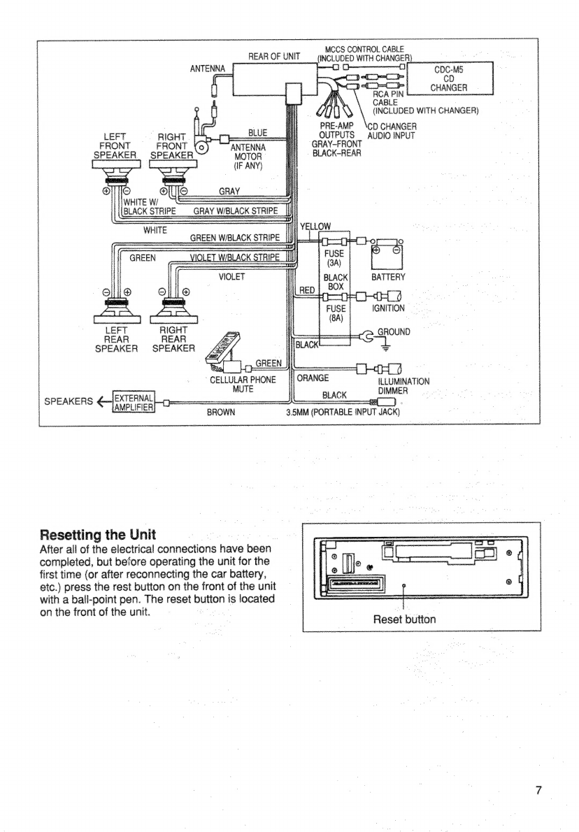
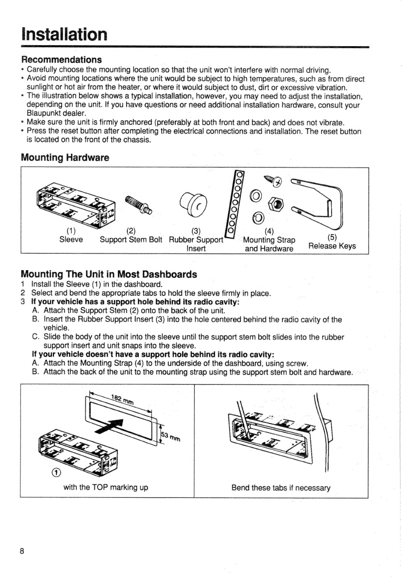
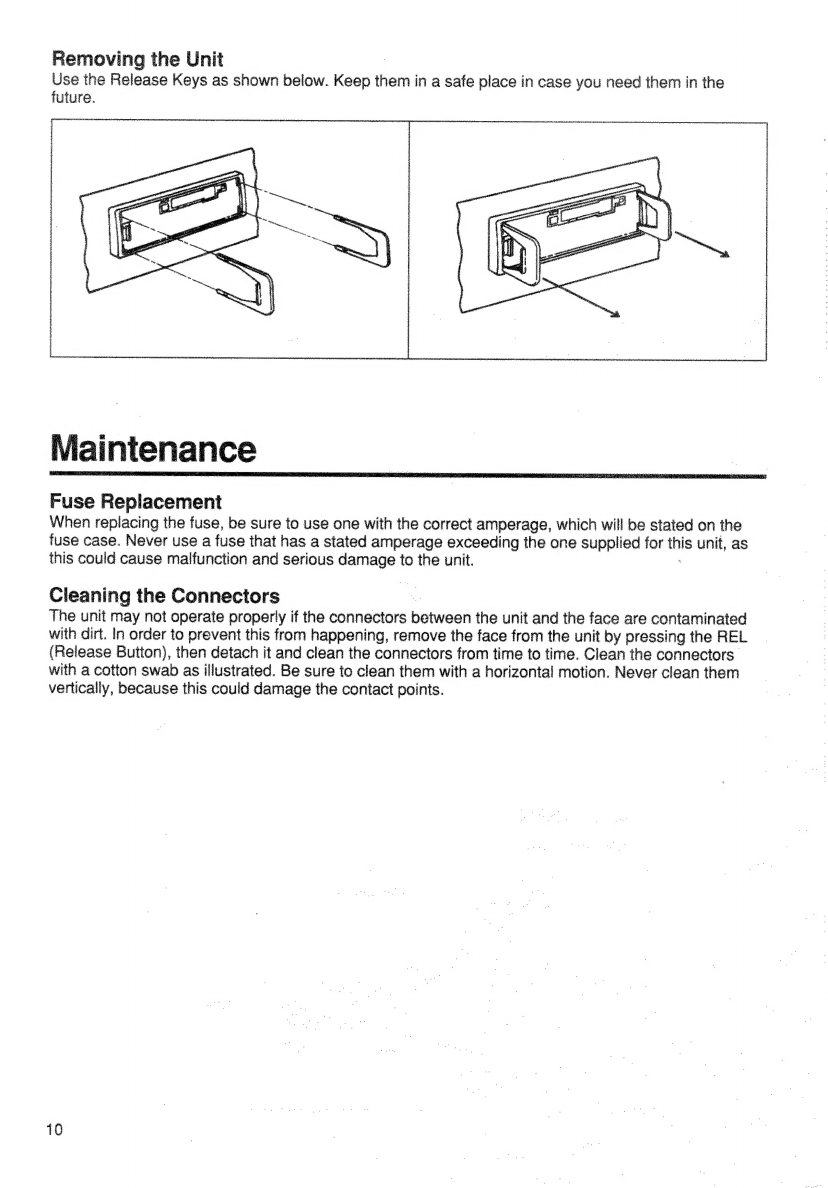
Bosch Blaupunkt LEXINGTON CM84 User manual

Changer
Control
and
Fully-Detachable
Face
|
Récepteur-Cassette
Stéreo
AM/FM
avec
Commande
de
Changement
de
CD
et
Face
Avant
Amovible
a
Receptor
FM/AM/Reproductor
de
Cassette
de
Alta
High-Power
FM/AM/Cassette
Receiver
with
CDG
Potencia
con
Control
para
Cambiadorde
CD
y
Panel
Frontal
Desmontable
(Caratula)
Radio
FM/AM/Toca-Fitas
de
Alta
Poténcia
\
com
Control
do
CD
Changer
e
Face
Removivel
a
‘@
BLAUPUNKT
Bosch
Group

FCC
Warning
The
equipment
has
been
tested
and
found
to
comply
with
the
limits
fora
Class
B
device,
pursuant
to
~
Part
15
of
the
FCC
Rules.
These
limits
are
designed
to
provide
reasonabie
protection
against
harmful
interference
in
a
residential
installation.
This
equipment
generates,
uses,
and
can
radiate
radio
frequency
energy,
and,
if
not
installed
and
used
in
accordance
with
instructions,
may
cause
harmful
interference
with
radio
communications.
However,
there
is
no
guarantee
that
radio
interference
will
not.
occur
in
particular
installation.
If
this
equipment
does
cause
harmful
interference
to
radio
or
television
—
reception,
which
can
be
determined
by
turning
the
equipment
off
and
on,
the
user
is
encouraged
to
try
—
to
correct
the
interference
by
one
or
more
of
the
following
measures:
*
Reorient
or
relocate
the
receiving
antenna.
i
*
increase
the
separation
between
the
equipment
and
receiver,
_
»
Connect
the
equipment
into.
an
outlet
or
circuit
different
from
that
which
the
receiver
is
connected.
*
Consult
the
dealer
or
an
experienced
radio/TV
technician
for
help.
You
are
cautioned
that
any
changes
or
modifications
not
expressly
approved
in
this
manual
could
void
your
authority
to
operate
this
equipment.
i
7
Owner’s
Record
=
The
model
and
warranty
numbers
are
located
on
the
top
of
the
unit.
Record
the
serial
number
in
the
space
provided
below.
Refer
to
these
numbers
whenever
you
call
upon
your
Blaupunkt
dealer
regarding
this
product.
Model
No.
LEXINGTON
CM84
Warranty
Number

Contents
English
FOC
Warning
.......:cccsscseeserees
ee
Bl
saeee
raha:
2
Owner's
RECOM
..........ccceceess
se
cac
eb
sdsiiecdunecics
wie
FOATUIOS
oo...
cccesensenveeeereoane
Loaareedeaustdtes
deter
ete:
4
PFO
CAULIONS
Gs
cyrszscets
ransos
bear
ck
i
senveioesapeneceancaesdicss
4
DG
ACAD
G
FACE
seers
aicvtnw
cs
esuspaed
in
geeede
eee
5
Electrical
Connections
and
installation
pituiates:
6
INSTAR
AUOMT
sc222oct
cts
cceuct
het
activstmecesteys
eres.
MA@INIQNANCE
oo.
ccccccccccusseceenececnseoeers
wale
tes
Riot
10
Specifications
.......
Sr
enteceseceas
sutras
teeuaapaiy
11
LOCBNOIN
OF
CONMIGIS:.cccdscccceoae
Sad
ee
2
instructions—General
Operation
...........c0.08
13
DSC—Direct
Software
Control
Operation
........
14
Fai:
OD
Or
atiO
Ns
istousieysecssaorunvanaanennwaivonees
15
Cassette
Player
Operation
oo...
ccesscsnnesseeeee
18
CD
Changer
Operation
.......cc.ccceccsscenssenereeernes
19
Portable
Input
Jack
...cscccsivsisssssesacecsseveaeeeeveeees
24
Troubleshooting
Guide
oo...
ceccscesesseessssees
22

Featu
Congratulations
on
your
purchase
of
the
Blaupunkt
LEXINGTON
CM84
FM/AM/Cassette
Receiver.
its
HDT
Phase
Locked
Loop
(PLL)
quartz
High-Definition
FM
and
AM
Tuner
and
high-quality
cassette
tape
player
provide
the
ultimate
in
sound
reproduction.
The
Travel
Store
feature
allows
you
to
automatically
load
six
receivable
FM
stations
into
the
tuner's
presets
as
you
travel
through
various
reception
areas.
¢
Tuner
Features:
*
Audio
Features:
~HDT
High-Definition
PLL
Tuner
~4
x
20
Watt
Integrated
Amplifier
~
24
FM/6
AM
Station
Presets
~4-Channel
RCA
Preamp
Output
including
6
FM
Travel
Store
Presets
~
Flex
Fader
~
Scan
and
Preset
Scan
—
Volume/Balance/Fader
Controls
~
Automatic
and
Manual
Tuning
~
Separate
Bass
and
Treble
Controls
~Local/Distant
Reception
Control
~
Loudness
Button
aa
~-—20
dB
Mute
»
Cassette
Features:
Re
~
Portable
input
Jack
~
Auto-Reverse
Semi-Logic
Cassette
_
~ASU
Impulse
Noise
Quieting
©
Mechanism
ne
~
Hard
Permailoy
Tape
Head
—
.
.
*
DSC
(Direct
Software
Control)
Features:
~
Fast-Forward/Rewind
7
~
Loudness
Boost
Levels
+9
or
+18
dB
~
NR
Cassette
Noise
Reduction
~
Scan
Sample
Time
—CPS-Cassette
Radio
Monitor
— |
~
Volume-Level
Memory
~
Turn-On
Message
Enter
«
CD
Changer-Control
Features:
|
-~-
Demo
Message,
Demo
On/Off
~
Controls
up
to
10
Blaupunkt
CDC-M5
CD
~-
Confirmation
Beep
On/Off
changers
_
-
=lo/dx
Tuning
Threshold
~
Disc
and
Track
Up/Down
and
Scan
|
~
Magazine,
Disc
and
Track
Mix
and
Repeat.
+
General
Features:
|
~
Fast
Track
Up/Down
~
Fully-Detachable
Faceplate
for
Security
w/Case
~
Changer
Disc
Namimng
~
Switchable
Clock/Function
LCD
Display
~
Pause/Play
Cellular
Phone
Mute
|
~
Cue/Review
~
Includes
Mounting
Hardware
and
Wire
Harness
_
~
TPM
Track
Program
Memory
_
=
DINASO
Mounting
Chassis
Your
LEXINGTON
CM84’s
fully-detachable
front
faceplate
makes
the
unit
useless
to
would-be
thieves,
Precautions
*
If
your
vehicle
was
parked
in
direct
Sunlight
resulting
in
a
considerable
rise
in
temperature
inside
the
__
vehicle,
allow
the
unit
to
cool
off
before
operating
your
unit.
¢
lf
no
power
connection
is
Supplied
to
the
unit,
check
the
connections
first.
If
everything
is
in
order,
check
the
fuse.
*
Ino
sound
comes
from
the
speakers
of
a
two-speaker
system,
set
the
fader
contro!
to
the
center
position.
*
You
are
cautioned
that
any
changes
or
modifications
not
expressly
approved
in
this
manual
could
void
your
warranty.
*
If
you
have
any
questions
or
problems
concerning
your
unit
that
are
not
covered
in
this
manual,
please
contact
your
Blaupunkt
dealer,

Detachable
Face
Detaching
&
Attaching
the
Face:
The
face
of
this
unit
can
be
detached
and
taken
with
you
to
prevent
it
from
being
stolen.
Detaching
the
Face:
Before
detaching
the
face,
be
sure
to
press
the
PWR
Button
first.
Then
press
the
REL
(Release)
Button
and
detach
the
face
by
gently
pulling
it
towards
you
as
illustrated.
Note:
Do
not
pull
it
straight
out
from
the
chassis.
Be
sure
not
to
drop
the
face
when
detaching
it
from
the
chassis.
Attaching
the
Face:
Apply
the
right
hand
side
of
the
face
to
the
chassis
by
sliding
(part
8)
of
the
face
to
(part
A)
at
the
front
of
the
chassis.
Gently
push
the
left
side
of
the
face
against
the
front
of
the
chassis
until
if
snaps
into
place.
Note:
Make
sure
that
the
face
is
inserted
right
side
up.
Do
not
press
against
the
display
window.
Do
not
press
hard
against
the
face
when
attaching
it
to
the
chassis,
it
may
be
easily
attached
with
gentle
pressure.
When
carrying
the
face
with
you,
put
it
in
the
carrying
case.
Do
not
expose
the
face
to
direct
sunlight,
heat
sources
such
as
hot
air
ducts
or
leave
it
in
a
humid
place.
Never
leave
it
on
the
dash
poard
of
a
vehicie
parked
in
direct
sunlight,
where
there
may
be
a
considerabie
rise
in
temperature
inside
the
vehicle.

Electrical
Connections
iinen
@/<?#&*>@!
To
avoid
the
aggravation
of
costly
mistakes
and
serious
damage
that
could
make
you
feel
this
way,
please
carefully
follow
all
of
the
instructions.
You'll
be
glad
you
did!
GENERAL
RECOMMENDATIONS
°
If
you're
not
confident
that
you
can
install
the
unit
correctly,
have
it
installed
by
a
qualified
Bieuoueld
installation
technician.
|
»
Design
and
specifications
subject
to
change
without
notice.
*
We
recommend
making
and
testing
all
electrical
connections
before
installing
the
unit,
*
Be
sure
to
detach
the
face
before
you
start
to
connect
or
install
the
unit.
ELECTRICAL
CONNECTIONS
Power
Connections
—
To
prevent
short
circuits
and/or
serious
damage:
*
Disconnect
the
vehicle
battery's
negative
terminal
before
making
connections.
°
Use
this
unit
only
with
negative
ground
12
Volt
(11-16
Volt)
direct
current
(DC).
«
Connect
leads
according
to
the
wiring
diagram.
«
The
total
amperage
required
by
the
blue
(remote)
lead
for
triggering
the
antenna
motor
must
not
exceed
100
mA.
We
don’t
recommend
connecting
these
leads
to
the
main
power
input
on
an
amplifier
or
anything
eise.
*
The
green
cellular
phone
interrupt
lead
is
for
muting
the
audio
sound
while
a
cellular
ida
is
in
use.
Connect
this
wire
to
the
appropriate
control
terminal
of
the
phone
equipment.
|
«
Connect
the
orange
lead
to
the
dashboard
dimmer
lead.
°
You
can
use
the
brown
lead
to
the
switch
on
an
external
amplifier.
Connect
this
lead
to
the
amplifier’s
remote
input.
(It
should
not
be
connected
to
the
amplifiers
power
input.)
»
Connect
the
red
power
input
lead
only
after
the
other
leads
are
connected.
And
be
sure
to
connect
it
to
a
positive
(+)
12
Volt
power
terminal
that
is
energized
only
when
the
ignition
key
is
set
to
the
accessory
position
or
on
position.
*
Connect
the
black
lead
to
a
grounded
metal
part
of
the
vehicle.
We
recommend
grounding
all
audio
system
biack
ground
leads
(head
unit,
external
amplifier,
etc.)
to
a
common
ground
point.
Speaker
Connections
The
Lexington’s
CM84’s
Flex
Fader
allows
you
to
fade
between
the
front
and
the
rear
of
the
vehicle
using
either
the
speaker
leads
and/or
the
preamp
outputs,
providing
you
tremendous
flexibility
in
configuring
your
speaker
arrangement:
*
You
can
connect
speakers
or
speakers
systems
to
each
of
the
units’
four
speaker
leads.
|
*
You
can
connect
the
4
RCA
preamp
outputs
to
external
amplifiers
and
power
up
to
four
speakers
or
speaker
systems
to
the
amplifiers.
(Blaupunkt
amplifiers
and
speakers
available
separately).
,
*
You
can
use
a
combination
of
these
two
methods,
allowing
your
Lexington
to
provide
sound
to
up
to
eight
speakers
or
speaker
systems.
Pre-Amp
Output
Connections
To
External
Amplifier(s)
—
To
prevent
short
circuits
serious
damage
to
the
unit
and/or
speakers:
*
Following
the
amplifier’s
instructions,
connect
Lexington
preamp
outputs
to
the
external
amplifier
and
connect
the
speaker(s)
or
speaker
system(s)
directly
to
the
amplifier.
CD
Changer
Connection
Follow
the
instructions
that
come
with
the
changer.

et
enn
ATR
arora
rb
HHS
AS
mT
ref
hh
AAA
edu
MR
I
RU
AHHH
AAP
Te
A
AAA
HAHIHAHE
HAMAR
MEAT
THEME
TOT
TITAS
MCCS
CONTROL
CABLE
REAR
OF
UNIT
—_
(NCLUDED
WITH
CHANGER
ANTENNA
_|
Slr
a
arora
c
|
at
Sia
Dal
CD
ut
-
Se
rica
Bn
=
CUANGED
f
'
Ais.
\
CABLE
eee,
ep
ft
|
GANS
(INCLUDED
WITH
CHANGER)
I
awe
|i)
Preawe.
‘co
cancer
LEFT
RIGHT.
ob
eeil]
OUTPUTS
_
AUDIO
INPUT
FRONT
|
FRONT
(Oo)
“ANTENNA
il
GRAY-FRONT
SPEAKER
SPEAKER
MOTOR.
TIL
BLACK-REAR
Gs
S
Eee
(IF
ANY)
i
SPEAKER
SPEAKER
&
7
ae
_
carne
|
i}
ORANGE
LLUMIN
ATION
SPEAKERS
G—|EXTERNAL|
——
BLACK
a)
|
Pre
4
AMPLIFIER
BROWN
35MM
(PORTABLE
INPUT
JACK)
Resetting
the
Unit
ai
|
After
all
of
the
electrical
connections
fae
been.
completed,
but
before
operating
the
unit
for
the
first
time
(or
after
reconnecting
the
car
battery,
etc.)
press
the
rest
button
on
the
front
of
the
unit
with
a
ball-point
pen.
The
reset
button
is
located
on
the
front
of
the
unit.
at
ae
Reset
button

installation
Recommendations
-
|
°
Carefully
choose
the
mounting
location
so
that
the
unit
won’t
interfere
with
normal
driving.
*
Avoid
mounting
locations
where
the
unit
would
be
subject
to
high
temperatures,
such
as
from
direct
sunlight
or
hot
air
from
the
heater,
or
where
it
would
subject
to
dust,
dirt
or
excessive
vibration.
»
The
illustration
below
shows
a
typical
installation,
however,
you
may
need
to
adjust
the
installation,
depending
on
the
unit.
If
you
have
questions
or
need
additional
installation
hardware,
consult
your
Blaupunkt
dealer.
;
*
Make
sure
the
unit
is
firmly
anchored
(preferably
at
both
front
and
back)
and
does
not
vibrate.
«
Press
the
reset
button
after
completing
the
electrical
connections
and
installation.
The
reset
button
is
located
on
the
front
of
the
chassis.
Mounting
Hardware
Oz
~
@
©
(2)
—
3)
|
|
(4)
Ey
Sleeve
Support
Stem
Bolt
Rubber
Support
Mounting
Strap
(5)
Insert
and
Hardware
_Helease
Keys
Mounting
The
Unit
in
Most
Dashboards
1
Install
the
Sleeve
(1)
in
the
dashboard.
2
Seiect
and
bend
the
appropriate
tabs
to
hold
the
sleeve
firmly
in
place.
3
ff
your
vehicle
has
a
support
hole
behind
its
radio
cavity:
A,
Attach
the
Support
Stem
(2)
onto
the
back
of
the
unit.
B.
Insert
the
Rubber
Support
Insert
(3)
into
the
hole
centered
behind
the
radio
cavity
of
the
vehicle.
C.
Slide
the
body
of
the
unit into
the
sleeve
until
the
support
stem
bolt
slides
into
the
rubber
support
insert
and
unit
snaps
into
the
sleeve.
if
your
vehicle
doesn’t
have
a
support
hole
behind
its
radio
cavity:
A.
Attach
the
Mounting
Strap
(4)
to
the
underside
of
the
dashboard,
using
screw.
B.
Attach
the
back
of
the
unit
to
the
mounting
strap
using
the
support
stem
bolt
and
hardware.
with
the
TOP
marking
up
Bend
these
tabs
if
necessary
_

Mounting
the
Unit
in
a
Japanese
Car
You
may
have
difficulty
mounting
this
unit
in
some
Japanese
cars
that
have
ISO
mounting
features.
in
this
case,
consult
your
Blaupunkt
dealer.
1
Runa
blade
along
the
slits
on
the
back
of
the
front
trim
ring
and
separate
it
from
the
unit.
Discard
the
trim
ring.
2
Use
the
vehicle’s
own
mounting
hardware
to
attach
the
unit.
2
TOYOTA
max.
size
M5x8
2
NISSAN
max.
size
M5x8
3.
ee
:
Bracket
Support
max.
size
|
Bracket
Support
to
dashboard/center
console

Removing
the
Unit
|
Use
the
Release
Keys
as
shown
below.
Keep
them
in
a
safe
place
in
case
you
need
them
in
the
future,
Maintenance
Fuse
Replacement
When
replacing
the
fuse,
be
sure
to
use
one
with
the
correct
amperage,
which
will
be
stated
on
the
fuse
case.
Never
use
a
fuse
that
has
a
stated
amperage
exceeding
the
one
supplied
for
ue
unit,
as
this
could
cause
malfunction
and
serious
damage
to
the
unit.
Cleaning
the
Connectors
The
unit
may
not
operate
properly
if
the
connectors
pawisen
the
unit
and
the
face
are
contaminated
with
dirt.
In
order
to
prevent
this
from
happening,
remove
the
face
from
the
unit
by
pressing
the
REL
(Release
Button),
then
detach
it
and
clean
the
connectors
from
time
to
time.
Clean
the
connectors:
with
a
cotton
swab
as
illustrated.
Be
sure
to
clean
them
with
a
horizontal
motion.
Never
clean
them
vertically,
because
this
could
damage
the
contact
points.
10

Specifications
Audio
Power
Specifications
_
POWER
OUTPUT
AND
TOTAL
HARMONIC
DISTORTION
13
watts
per
channel
minimum
continuous
average
power
into
4
ohms,
4
channels
driven,
from
30-15,000
Hz
with
no
more
than
1%
total
harmonic
distortion,
Other
Specifications
Power
amplifier
section
Outputs:
Speaker
output
with
bullet
connectors
Speaker
impedance:
4-8
ohms
Maximum
power
output:
20
W
x
4
(at
4
ohms)
.
Measured
at
14.4
V
Cassette
section
Signal-to-noise
ratio:
55
dB
Tape
WOW
and
Flutter:
<<
0.15%
Tape
frequency
response:
30
-
18,000
Hz+3
dB
Tuner
section
FM
Tuning
range:
87.7
-
107.9
MHz
Antenna
terminal:
External
antenna
connector
intermediate
frequency:
10.7
MHz
Sensitivity:
13
dBf
Selectivity:
75
dB
at
400kHz
Signal-to-noise
ratio:
.
65
dB(stereo),
70
dB
(mono)
Harmonic
distortion
at
1
kHz:
0.7%(stereo},
0.3%(mona)
Separation:
35d0B
Frequency
response:
30
-
15,000
Hzi3
dB
AM
Tuning
range:
530
-
1,710
KHz
.
Antenna
terminal:
External
antenna
connector
intermediate
frequency:
©
450
kHz
Sensitivity:
13
av
Signal-to-noise
ratio:
55
dB
Harmonic
distortion
at
1
kHz:
1.0%
General
;
Tone
controls:
Bass
+
10dB
at
100
Hz
Treble
+
10
dB
at
10
kHz
Power
requirements:
12
V
DC
car
battery
:
(negative
ground)
Operating
temperature:
—10°C
to
50°C
(15°F
to
120°F)
Dimensions:
Approx.
178
x
50
x
150mm
(wih/d)
(7
x
2
x
6
in.)
not
incl.
projecting
paris
and
controls
Mass:
Approx.
1.7kg
(3
Ib.
12
02.)
Supplied
accessories:
=
Mounting
hardware
(1
set)
Face
plate
case
(1)
Design
and
specifications
subject
to
change
without
notice.
Optional
accessories
CDC-M5
10
CD
Changer
9-404-230-283
Multi-Changer
Connection
Box
9-404-230-290
iP

Location
E>
|
15)
17
418
19]
16
20
21
1.
REL
(Release)
Button
AUD
(Audio
Select)
Button
Bass
Mode
Treble
Mode
Balance
Mode
Fader
Mode
Preset
Name
Storing
Name
Character
Completion
MUTE
Button
_
DSC
(Direct
Software
Control)
Button
SENS/CPS
(Cassette
Program
Search)
Button
Cassette
Eject
Button
|
Cassette
Door
FR
(Cassette
Fast-Rewind)
Button
FF
(Cassette
Fast-Forward)
Button
(8.&
9.
PROG
(Cassette
PROGram
Change)
.
TS/NR
(Travel
Store/Cassette
Noise
Reduction
)
Button
.
PS
(Radio
Scan/Preset
Scan)
.
PWR
(Power)
Button
.
+
Control:
Volume
+
Bass
+
Treble
+
Name
Character
Selection
TPM
Skip/Play
~
Control:
Volume
—
Bass
—
Treble
—
Name
Character
Selection
TPM
Skip/Play
FM
(FM
Band-Select)
Button
AM
(AM
Band-Select)
Button
SRC
(Audio
Source)
Button
14,
15.
16.
17.
12
ra“
C
oii
:
MUTE
Lestat
imeem
ne
me
oamianenainiememmmndlculinagianmimanmannammnen
acemiemeeninena
mim
inemenmaminamamamicenmuarmmanmuacerenereetier
eect
ere
EE
aE
TTT
UTN
TT
TT
STITT
TTT
.
A
Control
19.
20,
21,
22.
23.
24,
20.
26.
«27.
28,
29.
30.
31.
ANAGEMENT
SYSTEM
Ue
C
|
ba
Siena
i
|
LEXINGTON
OMB4
|
|
Sie”
|
Nhe!
MS
oso
HIGH
POWER
4.x
2
=
OPS
i
30|
23
[24
|
25
|
27
28
«31
22
Fade
to
Front
Automatic
Seek-Radio
Tuning
(Up)
DSC
(Direct
Software
Control)
Feature
Selection
CD
Disc
Search
(Forward)
|
CD
Fast
Track
Search
(Forward)
Clock
Hour
Adjustment
(Up)
V
Control!
Fade
to
Rear
Automatic
Seek-Radio
Tuning
(Down)
DSC
(Direct
Software
Control)
Feature
Selection
-
CD
Disc
Search
(Backward)
CD
Fast
Track
Search
(Backward)
Clock
Hour
Adjustment
(Down)
<<
Control
Balance
Left
Manual
Radio
Tuning
(Down)
|
DSC
(Direct
Software
Control)
Feature
Adjustment
.
CD
Track
Search
(Backward)
Audible
CD
Track
Review
(Backward)
Clock
Minute
Adjustment
(Down)
>>
Control
Balance
Right
Manual
Radio
Tuning
(Up)
DSC
(Direct
Software
Control}
Feature
Adjustment
CD
Track
Search
(Forward)
Audible
CD
Track
Review
(Forward)
Clock
Minute
Adjustment
(Up)
LCD
Display
Window
DISP
Button
NAME
Button
LD
(Loudness)
Button
FM/AM
Preset
Buttons
SCA
(CD
Scan)
Button
RPT
(CD
Repeat)
Button
MIX
(CD
Mix)
Button
[l>
(CD
Pause/Play)
Button
TPM
(Track
Program
Memory)
Button
RVR
IIe
sa
YrpNS
Sul
eelcevee
NAN
gl
TT
eee
ete
eee
te
eeennentenatenenatione®
Fate

Instructions
—
General
Operation
(Before
operating
the
unit
for
the
first
time
(or
after
reconnecting
the
car
battery,
etc.)
press
the
reset
button
on
the
front
of
the
unit
with
a
ball-point
pen.
The
reset
button
is
located
on
the
front
of
the
unit.
(See
page
7.)
|
_
Turning
Unit
On
Vehicle
ignition
must
be
on.
To
turn
unit
on,
press
PWR
Button
(12)
or
insert
a
tape.
Turning
Unit
Off
Press
the
PWR
Button
(12)
to
turn
the
unit
off.
Volume
,
ban
eh
€:
Press
the
+
and
~
Controls
(13
&
14)
to
increase
or
decrease
the
volume
to
the
desired
level.
The
relative
volume
level
is
indicated
in
the
Display
Window
(22).
Mute
To
reduce
the
volume
level
by
20
decibels,
press
the
MUTE
Button
(3).
The
“MUTE”
indicator
appears
in
the
Display
Window.
To
return
to
the
previous
volume
level,
press
it
again.
Loudness
Control
Press
the
LD
Button
(25)
to
increase
sound
level
of
the
low
and
high
frequencies
(60
Hz/
8
kHz)*,
especially
when
listening
at
low
volume
levels.
The
“LD”
indicator
appears
in
the
display.
To
cancel,
press
this
button
again.
Setting
the
Clock
| |
Turn
the
ignition
key
to
the
on
position
and
turn
the
unit
on
by
pressing
the
PWR
Button
(12).
If
the
clock
does
not
appear
in
the
display,
press
and
release
the
DISP
Button
(23)
until
the
clock
appears
in
the
display.
Press
the
DISP
Button
again
for
more
than
two
seconds
until
the
clock
starts
blinking.
Press
the
A
and
V
Controls
(18
and
19)
to
set
the
hour,
and
press
the
<<
and
>>
Controls
(20
and
21)
to
set
the
minutes.
Press
the
DISP
Button
again
to
activate
the
clock.
Changing
the
Information
Displayed
|
To
change
the
display
priority,
press
the
DISP
Button
(23)
and
the
display
changes
as
follows:
—
During
Radio
Reception:
Station
Name
(if
assigned)
—>
Frequency
—>
Clock
During
Cassette
Playback:
Program
Indication
—>
Clock
During
CD
Playback:
CD
Information
—->
Disc
Name
(If
assigned)
—>
Clock
During
Portable
Playback:
“PORTABLE”
—>
Clock
To
temporarily
change
the
display
between
non-clock
information
in
the
radio
and
changer
modes,
press
and
release
the
NAME
Button
(24).
After
two
seconds,
the
display
changes
back
to
the
priority
information.
Audio
Source
Selection
ee
3
Press
the
SRC
Button
(17)
to
change
the
active
audio
source
among
radio,
tape,
or
portable.
The
name
of
the
new
audio
source
is
shown
in
the
Display
for
at
least
one
second,
then
reverts
to
the
standard
display,
depending
on
the
audio
source.
Inserting
a
tape
at
any
time
will
turn
the
unit
on
or
switcn
the
unit
into
the
tape
mode.
:
:
Bass
and
Treble
|
os
.
Press
AUD
(Audio
Select)
Button
(2)
once
to
select
the
Bass
mode,
twice
for
the
Treble
mode.
The
level
is
indicated
in
the
Display
Window
(22).
Press
the
+
Control
(13)
or
—
Control
(14)
to
increase
or
decrease
the
level.
Four
seconds
after
you
complete
your
adjustments,
the
display
will
revert
back
to
showing
the
sound
source.
13

1
2
3
4
5
6
7
8 9
10.11
sinensis
——=
Mss
DISC
MANAGEMENT
SYSTEM
__»,
RiGhPaELn
3x2”
ces
CC
aa]
15
17
118
19
13.
14
16
20
21
Balance
Press
AUD
(Audio
Select)
Button
(2)
three
times
to
select
the
Balance
mode.
The
balance
is
indicated
in
the
Display
Window
(22).
Press
the
<<
Control
(20)
to
increase
the
left
speaker
output
or
press
the
>>
Control
(21)
to
increase
the
right
speaker
output
to
the
desired
level.
Fader
Press
AUD
(Audio
Select)
Button
(2)
four
times
to
select
the
Fader
mode.
The
level
of
or
for
front
and
back
speakers
is
indicated
in
the
Display
Window
(22).
Press
the
A
Control
(18)
to
decrease
the
rear
speaker
output.
Press
the
V
Control
(19)
to
decrease
the
front
speaker
output.
DSC
Direct
Software
Control
Operation
Your
Lexington
unit
allows
you
to
customize
many
operational
settings
to
your
personal
preference.
Here’s
how
to
adjust
the
settings:
1.
Press
the
DSC
Button
(4)
to
access
the
Direct
Software
Control
menu.
2.
Select
the
desired
DSC
function
by
pressing
and
releasing
the
/\
and
V
Buttons
(18
&
19).
3.
Adjust
the
function
as
desired
using
the
<<
and
>>
Controls
(20
&
21).
As
soon
as
you
move
to
the
next
function
or
after
eight
seconds,
your
changes
are
stored.
All
other
buttons
become
inactive
until
the
DSC
Button
is
pressed
again
or
until
approximately
eight
seconds
pass.
|
4.
Press
the
DSC
Button
(4)
to
complete
the
changes.
While
in
the
DSC
mode,
if
8
seconds
pass
and
no
buttons
are
pressed,
the
unit
automatically
exits
the
DSC
mode.
All
changes
made
in
the
DSC
mode
are
automatically
saved.
Here
are
the
LEXINGTON
CM84’s
DSC
functions:
Loudness
(LD)
Level
(LOUD
1
&
2)
—-
You
can
choose
between
two
loudness
levels
for
each
sound
source:
FM,
TAPE,
CD
CHANGER
and
PORTABLE.
(The
loudness
level
for
AM
is
automatically
set
to
LOUD
1.)
LOUD
1
is
+9
dB
boost
in
bass.
LOUD
2
is
a
+18
dB
boost
in
bass.
FM
Search
Sensitivity
Levels
(LO
1
&
2,
DX
1
&
2)
—
You
can
choose
between
low
or
oe
FM
sensitivity
thresholds
for
both
iocal
(lo)
and
distant
(dx)
stations.
Thresholds:
lol
>
65dBuVi-5
Only
very
strong
stations
lo2
>50dBuV+/-—-5
—
Also
strong
stations
ax
1>35dBuV+/-5
Also
distant
stations
dx2>25dBuV+-5
Also
very
distant
stations
14

Fix
Volume
Level
(FIX
VOL}
—
Sets
the
volume
level
that
is
heard
each
time
the
unit
is
turned
on.
You
can
adjust
the
voume
by
using
either
the
+
&
—
Controls
(13
&14)
or
the
<<
and
>>
Controls
(20
&
21).
|
Radio
Scan
Time
(SCAN
T
1-16)
—
Adjusts
the
time
the
unit
stops
at
a
station
during
scan
and
preset
scan
between
1
and
16
seconds.
(The
scan
time
for
CD
tracks
and
discs
is
factory
set
for
10
seconds.)
Confirmation
Tone
(BEEP
ON
&
OFF)
—
Allows
you
to
activate
or
defeat
an
audible
beep
that
sounds
when
a
button
is
pushed
or
an
operation
step
is
completed.
Turn-On
Message
(MSG
ON
&
OFF)
—
Turns
message
on
or
off
and
allows
you
to
create
your
own
turn
on
message
each
time
the
radio
is
turned
on.
Here’s
how
to
create
your
own
turn-on
message
of
up
to
16
characters:
.
Select
the
“Message
On”
DSC
function.
.
Press
the
AUD
Button.
.
Press
either
the
+
or
—
Buttons
(13
&
14)
to
select
the
desired
characters,
A-Z,
0-9
and
other
characters.
if
you
wish
to
put
a
blank
space
in
the
name,
select
the
“_”
(underbar).
.
Press
the
AUD
Button
after
locating
the
desired
character.
.
The
next
space
to
the
right
begins
to
flash.
Repeat
steps
3
and
4
for
each
desired
character.
After
the
sixteenth
character
(the
farthest
right
character)
is
completed,
the
first
(left-most)
character
begins
to
flash.
6.
To
store
your
turn-on
message,
press
the
A
or
V
Button
or
press
the
DSC
Button.
on
Go
Nh
Radio
Monitor
Function
(RM
ON)
—
This
feature
allows
you
to
have
the
radio
play
on
a
tape
is
being
rewound
or
fast-forwarded.
If
this
feature
has
been
activated,
RM
appears
in
the
Display
when
the
cassette
tape
is
in
use.
Demonstration
Mode
—
Your
unit
has
a
built-in
demonstration
message
mode
that
saioils
a
description
of
some
of
the
unit’s
key
features
across
the
Display.
(Should
this
unit
be
used
by
a
retailer
in
a
display,
it
would
allow
the
retailer
to
provide
customers
with
information
about
the
unit.)
To
activate
the
demonstration
mode:
Press
the
DSC
Button
(4).
All
of
the
units’
features
and
buttons
remain
available.
However,
if
one
minute
passes
during
which
no
buttons
have
been
pressed,
the
demonstration
message
continuously
scrolls
across
the
screen.
To
deactivate
the
demonstration
mode:
Press
the
DSC
Button
again
for
4
seconds.
The
demonstration
mode
is
also
active
whenever
the
ignition
voltage
(red
lead)
is
connected
but
no
back-
up
voltage
(yellow
lead)
is
connected.
The
yellow
lead
must
also
be
connected
to
make
it
possible
to
deactivate
the
demonstration
mode.
Radio
Operation
Band
Selection
Press
the
FM
Button
(15)
to
select
the
bands
FM1, FM2,
FM3,
and
FMT,
sequentially.
[You
can
also
press
and
release
the
TS
Button
(10)
to
switch
to
the
FMT
Band.]
Press
the
AM
Button
(16)
to
select
the
AM
band.
The
indicator
for
the
active
band
(FM1,
FM2,
FM3,
FMT
or
AM)
appears
in
the
Display
along
with
the
radio
frequency
being
received.
15

1+
2
3
4
§
6
i
8
9
10
11
{
on
PRO
4
ti
(==
DISC
MANAGEMENT
SySTEM
sw,
[||
FR
[i
pe
||
Nes
:
|
U
HIGH
POWER
4x20W
CPS
2
a
Gime
a
'
a
1
V2
—
EY
Sy
~—
eienntronntmeaecetetvanefriocmnnairerdareparuaineaicetesanenete
tre
15|
17
|
18
19
|
22
30|
23
[24
|
25
|
18
14
16 20
24
27
28
31.
29
Travel
Store
This
feature
allows
you
to
automatically
store
the
best-received
FM
stations,
which
is
especially
handy
when
you
travel
to
a
different
reception
area.
When
the
FM
mode
is
active,
pressing
the
TS
Button
(16)
changes
the
active
band
to
FMT.
To
store
the
most-receivable
FM
stations,
press
the
TS
Button
(10)
for
more
than
2
seconds.
The
lower
left
display
changes
to
FMT.
Beginning
with
the
last-received
FMT-Band
station,
the
unit
automatically
scans
the
FM
band
first
for
stations
receivable
with
a
minimum
85
dByV
sensitivity,
then
with
the
lo
and
dx
sensitivity
levels
you
select
under
DSC.
The
unit
then
stores
the
six
most-receivable
stations
and
switches
to
preset
1
on
the
FMT
Band.
Manual
Tuning
z
|
ae
Select
the
desired
band:
AM
or
FM.
Press
and
hold
the
<<
or
>>
Controls
(20
and
21)
until
the
desired
frequency
appears
in
the
Display.
$
Automatic
Seek
Tuning
7
Select
the
desired
band
AM
or
FM.
Press
and
release
the
A
and
V
Controls
(18
and
19)
to
seek
the
next
receivable
station.
Scan
Tuning
me
3
Press
the
PS
Button
(11)
for
more
than
2
seconds
to
scan
each
receivable
station.
Scan
tuning
will
stop
at
stations
receivable
using
the
reception
sensitivity
and
scan
time
specified
under
DSC.
(See
page
14.)
During
scan
tuning,
the
frequency
blinks
in
the
Display.
To
stop
the
scan
and
listen
to
a
Station
by
received,
press
the
PS
Button
again.
Search
Sensitivity
|
ce
To
have
the
automatic
and
scan
tuning
stop
only
at
strong
local
stations,
press
and
release
the
SENS
Button
(5).
“lo”
will
be
shown
in
the
display.
When
“dx”
is
displayed,
the
distant
reception
mode
is
in
effect
and
automatic
tuning
stops
at
ALL
receivable
stations,
weak
or
strong.
When
an
FM
stereo
program
with
a
signal
strength
of
at
least
20
dB
V
is
tuned
in,
the
stereo
indicator
(“CD”)
appears
in
the
Display
Window.
If
the
FM
stereo
program
is
weak
and
noisy,
the
unit.’
automatically
blends
the
signals,
eliminating
the
noise
and
gradually
converts
to
the
monaural
or
“mono”
mode.
The
stereo
symbol
will
disappear
from
the
Display.
16
HEeDELEEHHENNENERiUlE
eae
prcRdECE
Celene
Ele
Diememcny
ile
piel:
HPPA
MINDING
UIVEISS
OMIM
AM
ISL
SUSU
SENSIS
IMEI
NEI TTI

Preset
Tuning
Up
to
24
FM
and
6
AM
stations
can
be
stored
in
preset
memory.
1.
Tune
in
a
desired
station,
either
manually
or
automatically,
on
the
desired
Band,
AM,
FM1,
FMe2,
FM3,
or
FMT.
2.
Press
and
hold
any
one
of
the
six
Preset
Buttons
(26).
The
Preset
Button
number
will
appear
in
the
Display
Window.
After
two
seconds,
the
frequency
will
blink
twice,
indicating
that
the
station
has
been
stored
in
the
Button’s
memory
storage
for
that
Band.
3.
Repeat
the
above
procedure
with
the
rest
of
the
presets
for
each
Band,
as
desired.
4,
To
select
a
preset
station,
select
the
desired
band,
then
press
the
desired
Preset
Button.
Preset
Scan
To
review
the
stations
stored
in
the
Preset
Buttons,
press
and
release
the
PS.
(Preset
Scan)
Button
(11).
All
of
the
stations
stored
in
memory
will
be
scanned,
in-order,
for
the
amount
of
time
you've
programmed
under
DSC.
If
any
of
the
preset
frequencies
are
not
receivable
with
a
signal
strength
of
—
at
least
15
dBuV,
they
will
be
skipped
over.
To
stop
the
scanning
and
listen
to
the
station
being
received,
press
PS
Button
again
or
press
a
Preset
Button
or
another
tuning
control.
Preset/Station
Naming
|
You
can
enter
and
store
the
names
of
up
to
thirty
radio
stations
in
the
units
memory.
If
you
try
to
enter
more
than
30
names,
the
““*FULL**”
indication
will
Bpeeer
in
ae
si
aed
You
can
mets
enter
new
names
after
erasing
some
of
the
existing
names.
:
:
ee
ee
Ge
oo
1.
Tune
in
a
station
that
you
wish
to
name.
| |
one
2.
Press
the
NAME
Button
(24)
for
mare
than
two
ee
to
enter
the
“name
edit
mode.
”
3.
Press
either
the
+
or
—
Buttons
(13
&
14)
to
select
the
desired
characters,
A-Z,
0-9
and
other
characters.
If
you
wish
to
put
a
blank
space
in
the
name,
select
the
“_”
.
{underbar).
4.
Press
the
AUD
Button
after
locating
the
desired
character.
ae
5.
The
next
space
to
the
right
begins
to
flash.
Repeat
steps
3
and
4
for
each
desired
aneranee
up
to
eight
characters
can
be
used
per
name.
After
the
eight
character
(the
farthest
right
character)
is
completed,
the
first
(left-most)
character
begins
to
flash.
6.
To
store
the
name,
press
the
AUD
Button
for
more
than
two
seconds.
The
word
"STORING"
will
appear
in
the
Display
to
confirm
the
storage
of
the
name.
7.
To
name
another
station,
tune
in
the
station
using
A,
V,
<<
and
>>
(18-21)
and
repeat
steps
3,
4
|
and
6.
|
8.
To
complete
the
naming
process,
press
the
NAME
Button
for
more
than
two
seconds.
(If
after
8
seconds
you
do
not
press
the
NAME
Button
or
any
other
button,
the
unit
exits
the
naming
mode
|
and
automaticaily
stores
your
changes.)
Changing
a
Station
Name
aerate
re
Repeat
steps
1
to
8
in
Preset/Station
Naming,
changing
only
those
characters
that
you
wish
to
change.
ry
Erasing
a
Preset
Station
Name
:
_
eo
7
Repeat
steps
1
to
8
in
Preset/Station
Naming,
changing
all
of
the
siarcian:
in
the
name
to.”
[underbars].
In
step
6,
the
word
““DELETE*”
will
appear
in
the
Display
instead
of
“STORING”
t
to
—"
confirm
that
the
name
is
erased.
|
Displaying
a
Station
Name
See
“Changing
The
information
Displayed”
in
the
GENERAL
OPERATION
section.
FIRTROS
MMW
nereereD
CSET
NAR
ermeprRE
HEAR
eeneRriniiacimmmaannasininniseeaeneceeneinnenese
spamnmmenteremneeerenmsae.
Se
eee
se
et
ee
ee
Siete
keke
Oe
J
es
lk

hte
evant
sonra
1
CMS
DISC
MANAGEMENT
SYSTEM
o,f
Seeonnmomeresmanintimeemmenenanemcmermemmanmermrmnme
arralie
HIGH
POSYER
4x
20W
OPS
22
30;
23
|
24
|
25
-
27
62831
13
14
Cassette
Player
Operation
_
Cassette
Tape
Play:
>
Insert
cassette
into
Cassette
Door
(7).
Note:
Make
sure
that
the
side
of
the
cassette
with
the
tape
exposed
is
facing
to
the
right
side
and
that
all
slack
has
been
removed
from
the
tape
prior
to
_
insertion.
The
insertion
of
the
cassette
will
turn
the
unit
on
if
it
not
already
turned
on.
«
The
insertion
of
the
cassette
will
automatically
override
the
radio
(or
portable
input)
and
the
cassette
will
begin
to
play.
When
the
cassette
deck
is
being
used,
“CASS
1”
or
“CASS
2”
will
appeal
depending
on
which
tape
program
is
being
played.
¢
The
tape
will
continue
to
play
until
ejected,
until
the
radio
or
portable
input
is
selected
using
the
SRC
Button
(17),
or
until
the
unit
has
been
turned
off.
Noise
Reduction
Press
the
NR
Button
(24)
to
activate
the
high-cut
circuit
to
eres
high
frequency
noise
during
ane
play.
To
cancel,
press
this
button
again.
Auto-Reverse
Tape
Function
*
Automatic:
When
the
end
of
the
tape
(side
A
or
B,
program
1
or
2)
is
reached,
the
tape
will
automatically
reverse
direction
and
play
the
other
side
of
the
tape.
*
Manual:
To
reverse
tape
direction
during
playback,
press
both
tape
program
selector
buttons
—
[PR
(8)
and
OG
(9)]
at
the
same
time.
(PROG
is
short
for
program.
)
The
ce:
in
direction
and
in.
tape
program
will
be
confirmed
in
the
Display.
Fast
Winding
of
Tape
*
To
fast-rewind
tape,
press
FR
Button
(8).
To
fast-forward
tape,
press
FF
Button
(9).
*
To
stop
fast
winding,
press
the
other
fast-wind
button,
FR
or
FF.
Cassette
Program
Search
When
the
cassette
tape
mode
is
active,
press
the
CPS
Button
(5)
to
have
rewind
and
fast-forwarding
stop
at
the
beginning
of
the
next
selection.
|
Ejecting
Tape
«
Depress
the
Cassette
Eject
Button
(6)
completely
towards
the
face
of
the
unit.
The
apa
will
be
ejected
and
the
radio
(or
portabie
input)
will
play.
18

-D
Changer
Operation
The
Lexington
CM84
allows
you
to
contro!
up
to
10
CDC-M5
e
ahanuers.
Notes
on
Handling
Discs
|
Handie
the
disc
by
its
edge,
and
to
Keep
the
disc
clean,
do
not
touch
the
surface.
Do
not
attach
any
paper
or
tape.
Do
not
expose
the
disc
to
direct
sunlight
or
heat
sources,
such
as
hot-air
ducts,
or
leave
it
in
a
vehicle
parked
in
direct
suey
where
there
can
be
a
considerable
rise
in
temperature.
Cleaning
Discs
|
Before
playing,
clean
the
disc
with
a
compact
disc
cleaning
cloth.
Wipe
the
disc
from
the
center
of
the
disc
to
the
outer
edge
of
the
disc.
Do
not
use
solvents
such
as
benzine,
thinner,
commercially
available
cleaners
or
anti-static
spray
intended
for
analog
discs.
CD
Changer
Operation
Press
and
release
the
SRC
Button
(17)
to
locate
and
activate
the
desired
CD
changer.
The
Display
shows
the
Changer
Number
in
the
lower
left
corner.
It
also
shows
the
Disc
Number,
the
Track
Number,
and
the
elapsed
playing
time.
If
you
press
the
SRC
Button
(17)
during
CD
play,
the
CD
play
will
automatically
stop
and
the
next
available
audio
source,
including
any
other
CD
changers
installed,
will
be
activated.
Radio
—>
Cassette
—>
Changer
1
—>
Changer
2
etc.
—>
Portable
—>
Radio
Switching
To
The
Next
CD
Changer
(if
connected)
Press
and
release
the
SRC
Button
(17)
to
locate
and
select
the
(next)
changer
and
its
magazine.
Switching
To
Another
Disc
*
To
move
ahead
to
the
next
disc,
press
and
release
the
A
Bante
(18).
*
To
go
back
to
the
previous
disc,
press
and
release
the
V
Control
(19).
(If
you
keep
these
buttons
pressed,
the
unit
will
switch
to
fast
track
mode.)
Moving
To
Another
Part
of
The
Current
Disc
«
To
go
to
the
next
track,
press
and
release
the
>>
Control
(21).
To
go
back
to
the
beginning
of
the
track
being
played,
press
and
release
the
<<
Contro!
(20).
Press
these
controls
repeatedly
to
locate
previous
or
succeeding
tracks.
(You
can
also
press
and
hold
the
A
Control
(18)
and
the
V
Control
(19)
to
quickly
move
to
another
track.)
«
To
move
ahead
within
a
track,
press
and
hold
the
>>
Control
(21)
for
audible
cue.
To
go
back
within
a
track,
press
and
hold
the
<<
Control
(20)
for
review.
At
the
End
of
The
Disc
The
track
number
returns
to
“1”
and
the
disc
is
repeated
from
the
beginning
of
the
disc.
Repeat
Track
Repeat
—
To
play
the
currently
selected
track
repeatedly,
press
and
release
the
RPT
Button
(28)
as
needed
until
“RPT1”
appears
in
the
Display.
Disc
Repeat
—
To
play
the
currently
selected
disc
repeatedly,
press
and
release
the
RPT
Button
(28)
as
needed
until
“RPT2”
appears
in
the
Display.
Changer
Magazine
Repeat
—
To
play
the
currently
selected
changer
repeatedly,
press
and
release
the
RPT
Button
(28)
as
needed
until
“RPT3”
appears
in
the
Display.
To
cancel
RPT1,
RPT2
or
RPTS,
press
and
release
this
button
one
or
more
times,
as
needed,
to
remove
all
RPT
indications
from
the
Display.
Mix
Play
Disc
Mix
—
To
play
the
tracks
on
the
currently-selected
disc
in
random
aden
press
ang
paissee
the
MIX
Button
(29)
as
needed
until
“MIX1”
appears
in
the
Display.
19

17
148
19
|
22
30|
23
|
24
|
25
16
20»
21
27
28
31
#29”
|b
dc
demiendhdeteateieaiinmean
eee
nin
on
amnion
in
ninienendnaanainianisniainbiamanmmaniaganaiaoneneninansamnaiememmemnaunmnammmemarmemnamnaamraananata:ceramarcemmaaatanemmmetenneudenetanaanncuaaratmutene
tannins
Changer
Magazine
Mix
—
To
play
the
tracks
on
all
of
the
discs
in
the
currently-seliected
changer
in
random
order,
press
and
release
the
MIX
Button
(29)
as
needed
until
“MIX2”
appears
in
the
Display.
All
CD
Mix
—
To
piay
all
of
the
tracks
in
all
of
the
changers
and
built-in
player
in
random
order,
press
and
release
the
MIX
Button
(29)
as
needed
until
“MIX3”
appears
in
the
Display.
:
To
cancel
MIX1,
MiX2
or
MIX3,
press
and
release
this
button
one
or
more
times,
as
needed,
to
remove
all
MIX
indications
from
the
Display.
Track
Scan
=
:
| |
‘
To
play
the
first
10
seconds
of
each
track
in
order,
press
the
SCA
Button
(27)
during
CD
playback.
To
cancel,
press
it
again.
With
optional
CD
changer(s)
connected,
after
the
first
disc
has
been
scanned
using
the
Track
Scan
feature,
the
subsequent
disc
in
the
same
CD
changer
will
be
scanned,
with
10
seconds
of
each
track
played.
If
more
than
one
changer
is
connected,
when
the
last
track
of
the
last
disc
in
the
first
CD
changer
has
been
scanned,
the
first
disc
in
the
next
changer
will
be
scanned,
etc.
if
the
SCA
Button
(27)
is
pressed
during
MIX
play,
the
first
10
seconds
of
every
track
will
be
played
randomly.
Disc
Scan
:
To
play
the
first
10
seconds
of
every
disc,
press
the
SCA
Button
(27)
for
two
seconds
during
C
playback.
To
cancel,
press
it
again.
|
With
the
optional
CD
changer(s)
connected,
the
first
10
seconds
of
all
the
discs
in
the
currently-
selected
CD
changer
will
be
played
in
order.
When
the
last
disc
in
the
CD
changer
has
been
played,
the
disc
on
the
next
CD
player
(or
built-in
CD
player)
will
be
played.
Disc
Naming
You
can
enter
and
store
names
of
your
own
choice
onto
each
disc
(one
name
per
disc,
maximum
of
. .
eight
characters
per
name).
The
name
can
be
displayed
in
the
Display
Window
while
the
disc
is
being
located
and
played.
To
name
a
disc:
Play
the
disc
that
you
wish
to
name.
Press
the
NAME
Button
(24)
for
more
than
two
seconds
to
enter
the
“name
edit
mode.”
Press
either
the
+
or
—
Buttons
(13
&
14)
to
select
the
desired
characters,
A-Z,
0-9
and
other
characters.
If
you
wish
to
put
a
blank
space
in
the
name,
select
the.“_”
(underbar).
Press
the
AUD
Button
after
locating
the
desired
character.
|
s
WNo
Table of contents
Other Bosch Car Receiver manuals

Bosch
Bosch BLAUPUNKT RDM 126 User manual

Bosch
Bosch CCD series User manual

Bosch
Bosch CR24 User manual

Bosch
Bosch Rotterdam UBT40 User manual

Bosch
Bosch Coach smartPanel NAFTA 7 620 210 046 User manual

Bosch
Bosch MR 12 User manual

Bosch
Bosch Blaupunkt Coburg CM 62 User manual

Bosch
Bosch CCA 47 User manual

Bosch
Bosch Blaupunkt Saint Malo RCM 127 User manual

Bosch
Bosch Blaupunkt Freiburg RCM 45 User manual