manuals.online logo
Brands
  1. Home
  2. •
  3. Brands
  4. •
  5. Bosch
  6. •
  7. Industrial Equipment
  8. •
  9. Bosch POPIT D9127U/T User manual

Bosch POPIT D9127U/T User manual

POPIT D9127U/T
Mounting Instructions
• Remove the PCB before mounting the POPIT.
• Leave Switch 0 ON when installing the D9127 with a D7212B1,
D8112, or D9112B1.
• To install the D9127 with a D9412, refer to the 9000 Series
Operation and Installation Guide (P/N: 74-07692-000) for correct
Switch 0 placement.
• To install the D9127 with a D9412G or D7412G, refer to the
D9412G/D7412G Operation & Installation Guide
(P/N: 43488)for correct Switch 0 placement.
• To install the D9127 with a D9412GV2 or D7412GV2, refer to
the D9412GV2/D7412GV2 Operation and Installation Guide
(P/N: F01U003641) for correct Switch 0 placement.
• To install the D9127 with a D7212G, refer to the D7212G
Operation and Installation Guide (P/N: 4998138544) for correct
Switch 0 placement.
• To install the D9127 with a D7212GV2, refer to the D7212GV2
Operation and Installation Guide (P/N: F01U003805) for correct
Switch 0 placement.
For additional D9127 installation information, refer to the D9412GV2/
D7412GV2 Approved Applications Compliance Guide (P/N: F01U003639).
Remove the Cover
1. Insert a small flat-head screwdriver into one of the small slots in the
side of the POPIT.
2. Twist the screwdriver and remove the cover.
Remove the PCB
1. Grasp the terminal block on the PCB in one hand.
2. Three tabs hold the PCB. At the end with the two tabs, carefully but
firmly, push one tab away from the PCB and lift the corner.
3. Carefully but firmly, push the other tab away from the PCB and lift
the entire PCB from the base.
Mount the POPIT Base
Mount the POPIT using the supplied hardware to prevent shorting the
PCB.
Replace the PCB
1. Grasp the terminal block on the PCB with one hand. Insert the DIP
switch end of the PCB under the single tab.
2. Carefully but firmly, pull the two tabs on the opposite ends away
from the PCB.
3. Gently lay the PCB in place and, if necessary, carefully, push the
two tabs toward the PCB until the PCB is firmly in place.
4. Replace the cover.
Electrical Specifications
Operating Voltage: Nominal 12 VDC supplied by control panel.
Operating Current: 0.5 mA per D9127U/T Module
Wiring Instructions
For more information on POPIT installation (including wire type,
length, and run) and programming, refer to the D8125 POPEX
Installation Manual (P/N: 74-04247-000) and control panel
operation, installation, and programming manuals.
When using 12 AWG (0.1 mm) maximum wire, use solid
wire. If you use stranded wire, be careful inserting the wire
into the terminal block.
Table 1: ZONEX Point Address Chart
Switch2 Switch Switch
Address1 0 1 2 3 4 5 6 Address 0 1 2 3 4 5 6 Address 0 1 2 3 4 5 6
009 •••••••029 •••••049 •••••
010 ••••••030 ••••050 ••••
011 ••••••031 ••••051 ••••
012 •••••032 •••052 •••
013 ••••••033 •••••053 ••••
014 •••••034 ••••054 •••
015 •••••035 ••••055 •••
016 ••••036 •••056 ••
017 ••••••037 ••••057 •••••
018 •••••038 •••058 ••••
019 •••••039 •••059 ••••
020 ••••040 ••060 •••
021 •••••041 ••••••061 ••••
022 ••••042 •••••062 •••
023 ••••043 •••••063 •••
024 •••044 ••••064 ••
025 ••••••045 •••••065 ••••
026 •••••046 ••••066 •••
027 •••••047 ••••067 •••
028 ••••048 •••068 ••
1Points 9 to 127 (D9412G); Points 9 to 75 (D7412G). 2A dot (
•
) in the Switch column indicates the switch is set to ON.
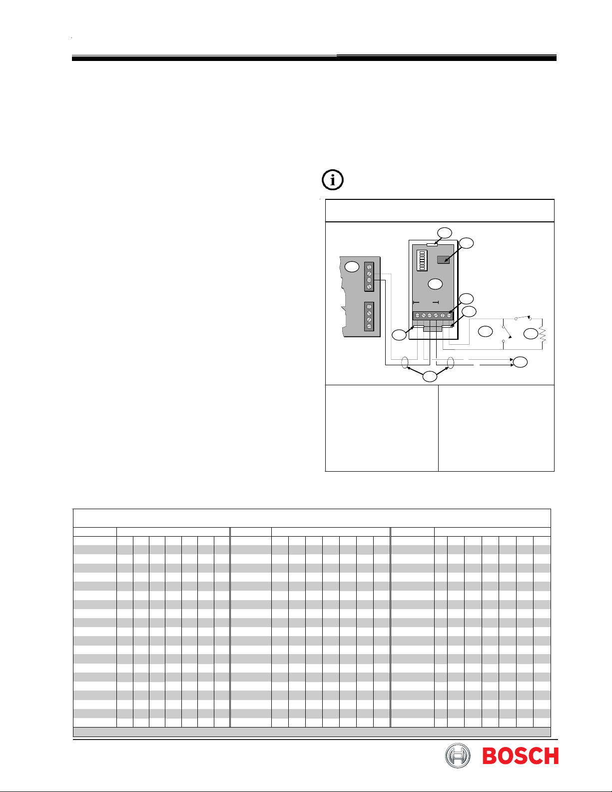
Figure 1: POPIT Wiring
-
-
+
+
GND
OUT
IN
AUX
DATA LOOP
- - + + - +
(-)
(+)
1
2
3
4
7
56
8
3
3
9
1 - D8125 POPEX Module
2 - D9127U/T POPIT
Module
3 - Tab
4 - Reed switch (D9127T
only)
5 - Detector loop
6 - 33 k
Ω
EOL resistor
7 - Terminals (all):
12 AWG solid
(maximum);
22 AWG (0.1 mm)
stranded (minimum)
8 - Zone expansion loop to
other POPITs
9 - Supervised
10/08
D9127U/T POPIT
Page 2 of 2
© 2008 Bosch Security Systems, Inc. 4998132020-04
130 Perinton Parkway, Fairport, NY 14450-9199 USA Mounting Instructions
(800) 289-0096
Table 1 (continued): ZONEX 1 Point Address Chart
Switch2Switch2Switch2
Address10 1 2 3 4 5 6 Address10 1 2 3 4 5 5 Address10 1 2 3 4 5 6
069 •••089 •••••109 ••••
070 ••090 ••••110 •••
071 ••091 ••••111 ••6
072 •092 •••112 ••
073 ••••••093 ••••113 ••••
074 •••••094 •••114 •••
075 •••••095 •••115 •••
076 ••••096 ••116 ••
077 •••••097 ••••117 •••
078 ••••098 •••118 ••
079 ••••099 •••119 ••
080 •••100 ••120 •
081 •••••101 •••121 ••••
082 ••••102 ••122 •••
083 ••••103 ••123 •••
084 •••104 •124 ••
085 ••••105 •••••125 •••
086 •••106 ••••126 ••
087 •••107 ••••127 ••
088 ••108 •••1283
1Points 9 to 127 (D9412G); Points 9 to 75 (D7412G).
2A dot (
•
) in the Switch column indicates the switch is set to ON.
3The control panel reserves Point 128 for internal use.
Table 2: ZONEX 2 Point Address Chart
Switch Switch Switch
Address 0 1 2 3 4 5 6 Address 0 1 2 3 4 5 6 Address 0 1 2 3 4 5 6
129 •••••••169 •••••209 •••••
130 ••••••170 ••••210 ••••
131 ••••••171 ••••211 ••••
132 •••••172 •••212 •••
133 ••••••173 ••••213 ••••
134 •••••174 •••214 •••
135 •••••175 •••215 •••
136 ••••176 ••216 ••
137 ••••••177 •••••217 ••••
138 •••••178 ••••218 •••
139 •••••179 ••••219 •••
140 ••••180 •••220 ••
141 •••••181 ••••221 •••
142 ••••182 •••222 ••
143 ••••183 •••223 ••
144 •••184 ••224 •
145 ••••••185 ••••225 •••••
146 •••••186 •••226 ••••
147 •••••187 •••227 ••••
148 ••••188 ••228 •••
149 •••••189 •••229 ••••
150 ••••190 ••230 •••
151 ••••191 ••231 •••
152 •••192 •232 ••
153 •••••193 ••••••233 ••••
154 ••••194 •••••234 •••
155 ••••195 •••••235 •••
156 •••196 ••••236 ••
157 ••••197 •••••237 •••
158 •••198 ••••238 ••
159 •••199 ••••239 ••
160 ••200 •••240 •
161 ••••••201 •••••241 ••••
162 •••••202 ••••242 •••
163 •••••203 ••••243 •••
164 ••••204 •••244 ••
165 •••••205 ••••245 •••
166 ••••206 •••246 ••
167 ••••207 •••247 ••
168 •••208 ••2483
1Points 129 to 247 (D9412G only).
2A dot (
•
) in the Switch column indicates the switch is set to ON.
3The control panel reserves Point 248 for internal use.

Other Bosch Industrial Equipment manuals

Bosch EL-53000 User manual

Bosch

Bosch EL-53000 User manual

Bosch Rexroth WT 2 User manual

Bosch

Bosch Rexroth WT 2 User manual

Bosch T40211 User manual

Bosch

Bosch T40211 User manual

Bosch TS0800 User manual

Bosch

Bosch TS0800 User manual

Bosch Rexroth RE 90300-B User manual

Bosch

Bosch Rexroth RE 90300-B User manual

Bosch AVENAR panel User guide

Bosch

Bosch AVENAR panel User guide

Bosch BEA 750 User manual

Bosch

Bosch BEA 750 User manual

Bosch WORCESTER GREENSTAR User manual

Bosch

Bosch WORCESTER GREENSTAR User manual

Bosch ADV 82 User manual

Bosch

Bosch ADV 82 User manual

Bosch rexroth Sytronix SvP 7020 PFC 03 User manual

Bosch

Bosch rexroth Sytronix SvP 7020 PFC 03 User manual

Bosch BH 500 100-6 Series User manual

Bosch

Bosch BH 500 100-6 Series User manual

Bosch XDK 110 User manual

Bosch

Bosch XDK 110 User manual

Bosch rexroth PSK User manual

Bosch

Bosch rexroth PSK User manual

Bosch KPS 003 User manual

Bosch

Bosch KPS 003 User manual

Bosch rexroth COIL D36 User manual

Bosch

Bosch rexroth COIL D36 User manual

Bosch Rexroth BS 2/C Series User manual

Bosch

Bosch Rexroth BS 2/C Series User manual

Bosch Rexroth TS1 User manual

Bosch

Bosch Rexroth TS1 User manual

Bosch Rexroth HQ 2/C-H User manual

Bosch

Bosch Rexroth HQ 2/C-H User manual

Bosch Rexroth UPE2 Operating instructions

Bosch

Bosch Rexroth UPE2 Operating instructions

Bosch Rexroth WS290 User manual

Bosch

Bosch Rexroth WS290 User manual

Bosch RA1171 Assembly instructions

Bosch

Bosch RA1171 Assembly instructions

Bosch Rexroth GTE Series Technical manual

Bosch

Bosch Rexroth GTE Series Technical manual

Bosch BS 2/R User manual

Bosch

Bosch BS 2/R User manual

Bosch SVE2510 QR User manual

Bosch

Bosch SVE2510 QR User manual

Popular Industrial Equipment manuals by other brands

Jäger BS55-M060.01 K1,3-S15 manual

Jäger

Jäger BS55-M060.01 K1,3-S15 manual

SFS intec Cab-R 3D-001 Fitting and adjustment instructions

SFS intec

SFS intec Cab-R 3D-001 Fitting and adjustment instructions

Alpha Technologies Cordex 24-3.1kW Installation & operation manual

Alpha Technologies

Alpha Technologies Cordex 24-3.1kW Installation & operation manual

SCHUNK SWG 10 Assembly and operating manual

SCHUNK

SCHUNK SWG 10 Assembly and operating manual

ASTEC JCI 1400 RA Operation manual

ASTEC

ASTEC JCI 1400 RA Operation manual

Big Daishowa KAISER CK PRESETTER Operation manual

Big Daishowa

Big Daishowa KAISER CK PRESETTER Operation manual

Big Daishowa HMC20S-NRA Operator's manual

Big Daishowa

Big Daishowa HMC20S-NRA Operator's manual

OSO HOTWATER Nano - N 5 manual

OSO HOTWATER

OSO HOTWATER Nano - N 5 manual

Weidmüller POWERSTRIPPER AM 12 operating manual

Weidmüller

Weidmüller POWERSTRIPPER AM 12 operating manual

CSL DigiAir Pro 3 manual

CSL

CSL DigiAir Pro 3 manual

Franke LVA Technical documentation

Franke

Franke LVA Technical documentation

ABB HT568005 Operation manual

ABB

ABB HT568005 Operation manual

SKETCHNBUILD SNB-K96 manual

SKETCHNBUILD

SKETCHNBUILD SNB-K96 manual

Sumitomo FC-6S+ Operation manual

Sumitomo

Sumitomo FC-6S+ Operation manual

ULB TLB-R1000-480-OS instruction manual

ULB

ULB TLB-R1000-480-OS instruction manual

Kval 960-3 Operation and service manual

Kval

Kval 960-3 Operation and service manual

HBM FIT 7A operating manual

HBM

HBM FIT 7A operating manual

Krone 5XL-R/GL Original operating instructions

Krone

Krone 5XL-R/GL Original operating instructions

manuals.online logo
manuals.online logoBrands
  • About & Mission
  • Contact us
  • Privacy Policy
  • Terms and Conditions

Copyright 2025 Manuals.Online. All Rights Reserved.