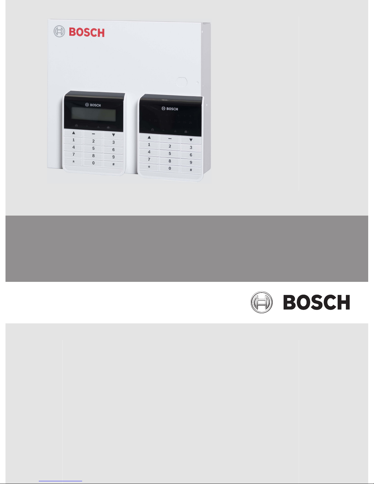
Bosch AMAX 2100 User manual

AMAX 2100 / 3000 / 4000
en Installation Guide


Table of contents
1Graphics 6
2Safety 8
3Short Information 10
3.1 Keypad Indicators 10
4System overview 12
5Optional Modules and Peripheral Devices 13
5.1 Bosch Option Bus 13
5.2 Keypad 14
5.2.1 General 14
5.2.2 Address Setting 14
5.2.3 Wiring 15
5.2.4 Status Indicator 15
5.3 DX2010 16
5.3.1 General 16
5.3.2 Address Setting 16
5.3.3 Wiring 17
5.3.4 Status Indicator 18
5.4 DX3010 18
5.4.1 General 18
5.4.2 Address Setting 18
5.4.3 Wiring 19
5.4.4 Status Indicator 19
5.5 B426 19
5.5.1 General 19
5.5.2 Address Setting 19
5.5.3 Wiring 20
5.5.4 Status Indicator 20
5.6 B450 with B442 21
5.6.1 General 21
5.6.2 Address Setting 21
5.6.3 Wiring 21
5.6.4 Status Indicator 21
5.7 DX4020-G 22
5.7.1 General 22
5.7.2 Address Setting 22
5.7.3 Wiring 22
5.7.4 Status Indicator 23
5.8 RF Radion Receiver 24
5.8.1 General 24
5.8.2 Address Setting 24
5.8.3 Wiring 24
5.8.4 Status Indicator 24
6Installation 25
6.1 Module Installation 25
6.2 Battery Installation 26
6.3 System Power Up 27
6.4 System Status Indicator 28
AMAX 2100 / 3000 / 4000 Table of Contents | en 3
Bosch Sicherheitsysteme GmbH Installation Guide 2014.11 | 02 | F.01U.267.112

6.5 Certification 28
6.5.1 EN 50131-3 Grade 2, Environmental Class 2 - AMAX 2100 / 3000 / 4000 29
6.5.2 NFA2P AFNOR / CNPP - AMAX 2100 / 3000 / 4000 29
6.5.3 INCERT - AMAX 4000 30
6.5.4 SFF – AMAX 2100 / 3000 / 4000 30
7Settings 32
7.1 Communication and Reporting 32
7.1.1 Receivers 32
7.1.2 Reports 38
7.1.3 Automatic Test Report 42
7.1.4 Dual IP 42
7.1.5 Remote Access 43
7.1.6 Remote PC 43
7.1.7 Call back and Domestic Call 44
7.1.8 Ring Times 44
7.2 Users and Codes 45
7.2.1 User Code 45
7.2.2 Installer Code 45
7.2.3 Code Length 48
7.2.4 Code Reporting 48
7.2.5 Code Permissions 48
7.2.6 Macro Configuration 49
7.3 Zones 49
7.3.1 Add / Delete Zone 49
7.3.2 Pulse Count Duration 60
7.3.3 Cross Zone Timer 60
7.3.4 Zone Function Settings 60
7.3.5 Zone Indication Keypad and Event Log 64
7.4 Keypads and Areas 65
7.4.1 Keypad Area 65
7.4.2 Area Timing 65
7.4.3 Common Area 65
7.4.4 Keypad Indication 66
7.4.5 Keypad Lockout 66
7.5 System 66
7.5.1 System Setting 66
7.5.2 System View 69
7.5.3 System Factory Default 70
7.6 Outputs and Sirens 71
7.6.1 Outputs 71
7.6.2 Sirens 78
7.7 RF Devices 78
7.7.1 RF Options 78
7.7.2 RF Devices / User 78
7.8 Key Programming 79
8Configuration 81
8.1 Programming with the Keypad 81
8.1.1 Text Keypad Programming 81
8.1.2 LED/LCD Keypad Programming 92
4en | Table of Contents AMAX 2100 / 3000 / 4000
2014.11 | 02 | F.01U.267.112 Installation Guide Bosch Sicherheitsysteme GmbH

8.2 PC Programming 93
8.2.1 Direct Connection 95
8.2.2 Modem Connection 98
8.2.3 IP Connection 101
9Address Programming 105
9.1 Communication and Report Programming 105
9.1.1 Receiver Programming 105
9.1.2 Reports Programming 108
9.1.3 Communication Operations Programming 109
9.2 User and Code Programming 112
9.2.1 User Code Programming 112
9.2.2 Installer Code Programming 116
9.2.3 Code Length Programming 116
9.2.4 Code Permission Programming 116
9.2.5 Macro Programming 117
9.3 Zone Programming 118
9.3.1 Add/Delete Zone Programming 118
9.3.2 Zone Function Programming 123
9.3.3 Pulse Count Duration Programming 126
9.3.4 Zone Cross Timer Programming 126
9.4 Keypad and Area Programming 127
9.4.1 Keypad Area Programming 127
9.4.2 Area Timing Programming 127
9.4.3 Common Area Programming 128
9.4.4 Keypad Indication Programming 128
9.4.5 Keypad Lockout Programming 129
9.5 System Programming 129
9.5.1 System Setting Programming 129
9.5.2 System Factory Default Programming 132
9.6 Output and Siren Programming 132
9.6.1 Output Programming 132
9.6.2 Siren Programming 134
9.7 RF Device Programming 134
10 Troubleshooting 137
10.1 General Trouble 137
10.2 Trouble Fault Inquiry 140
11 Maintenance 153
11.1 Firmware Upgrade with the ICP-EZRU2 Upgrade Key 153
12 Technical Data 154
AMAX 2100 / 3000 / 4000 Table of Contents | en 5
Bosch Sicherheitsysteme GmbH Installation Guide 2014.11 | 02 | F.01U.267.112

Graphics
Figure 1.1: Wiring diagram for AMAX panel 2100 / 3000
1
6en | Graphics AMAX 2100 / 3000 / 4000
2014.11 | 02 | F.01U.267.112 Installation Guide Bosch Sicherheitsysteme GmbH

Program Key Port
GND
-
+
A C
AC
Transformer
Battery
Tamper
L2 COM COM COM
L1a L3 L4 L5 L6 L7 L8
L9
COM
COM
COM
COM
L10
L11
L12
L13
L14
L15
L16
P0+4
R
B
G
Y
AUX1
-
AUX2
-
AUX1
+12V
Y
G
B
R
RINGRHTHTIP
L1b
P0+3
P0+
P0-2
P0-1
Zones
Bosch Option
Bus2 < 900mA
+12V
+0 V
1
2
3
3
1 Tamper Switch
2 Zone Switch
3 EOL 2,2 k
4 NO + NC
3
2
3
2
Fuse 1 A
PO+4: < 750mA
PO+3: < 750mA
PO -2: < 500mA
PO -1: < 500mA
230V ~50Hz
230mA
Wachdog
output
<100mA
12V < 18Ah
18VAC@50VA
Zones
AUX 1: < 900mA
AUX 2: < 900mA
AUX Power
Fire
Intrusion
3
3
2
Slow flash: Normal state
On: Trouble state
Off: Trouble state
_
_
_
_
_
_
_
_
+12V
+12V
+12V
COM
_
12V 7Ah
AUX2
+12V
_
COM
supervised
PO-5
Z1
2
23
3
Keypads:
IUI-AMAX4-TEXT
IUI-SOL-TEXT
IUI-AMAX3-LED16
IUI-AMAX3-LED8
Keypads:
IUI-AMAX-LED8
IUI-AMAX-LCD8
I/O Moduls:
DX2010 Adr. 103 - 108
DX3010 Adr. 150 - 151
DX4010 Adr. 253
Communicators:
DX4020G Adr. 134
B426 Adr. 134(6) / 250(9)
RF Receiver:
RF3227E 1=
RFRC-OPT 1= (1)
1 =
2=
3 =
4 =
1=
2=
Bosch Option
Bus1 < 900mA
COM
R
BGY
R
B
G
Y
R
B
G
Y
♥
IUI-AMAX3 +4 Keypad
3
1
2
1
Factory
Default
5-16 Inst. Guide
I
2000mA
100 Ω - 2,2 k
_
<
∑
3
Figure 1.2: Wiring diagram for AMAX panel 4000
AMAX 2100 / 3000 / 4000 Graphics | en 7
Bosch Sicherheitsysteme GmbH Installation Guide 2014.11 | 02 | F.01U.267.112

Safety
Danger!
Electricity
Injuries due to electricity are possible if the system is not operated correctly or if the system
is opened or modified not accordingly to this manual.
– Disconnect all Telecommunication Network Connectors before switching off the power.
– To switch off the power, make sure to have a circuit breaker available.
– Make sure that the system is switched off during the installation and wiring process.
– Only open or modify the system accordingly to this manual.
– Make sure to connect the system to a socket-outlet with a protective grounding contact.
– Only qualified installers /service personnel are allowed to install this system.
Danger!
Battery
Injuries due to electric shock, fire or explosion are possible if the battery is handled or
connected incorrectly.
– Always handle the battery carefully and replace it carefully.
– Make sure that the grounding terminal is always connected and that N, L1 or xx are
connected correctly.
– Make sure to first disconnect the positive wire of the battery when removing it from the
system.
– Be careful when connecting the positive (red) wire and the "BATT +" port of the system.
Make sure not to short-circuit with the "BATT +" port of the AMAX panel or the housing to
prevent electric arc from occurring.
Danger!
Electrostatic-sensitive components
Injuries due to electric shock are possible if anti-static steps are not followed.
– Always contact the grounding terminal before installing the system to discharge the
possibly carried static electricity.
!
Caution!
Sensitive components
Damage of sensitive components is possible if the system is not handled carefully or if the
system is opened or modified not accordingly to this manual.
– Always handle the system carefully.
– Only open or modify the system accordingly to this manual.
!
Caution!
Battery
Damage or contamination of the system is possible if the battery is not handled correctly or if
the battery is not replaced on a regular basis.
– Only use a non-spillable battery.
– Place a label with the last replacement date on the battery.
2
8en | Safety AMAX 2100 / 3000 / 4000
2014.11 | 02 | F.01U.267.112 Installation Guide Bosch Sicherheitsysteme GmbH

– Under normal conditions of use, replace the battery every 3-5 years.
– Recycle the battery after replacement according to local regulations.
!
Caution!
Installation
Damage or malfunction of the system is possible if the system is not mounted and installed
correctly.
– Place the system inside the monitored area on a stable surface.
– Make sure to mount keypads on the inner side of the monitored area.
– Once the system is tested and ready to use, secure the enclosure door and additional
enclosures with screws.
!
Caution!
Maintenance
Damage or malfunction of the system is possible if it is not maintained on a regular basis.
– It is recommended to test the system once a week.
– Make sure to get the system maintained four times a year.
– Only qualified installers /service personnel are allowed to maintain this system.
AMAX 2100 / 3000 / 4000 Safety | en 9
Bosch Sicherheitsysteme GmbH Installation Guide 2014.11 | 02 | F.01U.267.112

Short Information
Congratulations on selecting the AMAX panel for your installation. Spend some time reading
through this guide and familiarize yourself with the outstanding installation and operation
features of this system so that you can get the most from your unit. In all aspects of planning,
engineering, styling, operation, convenience, and adaptability, we try to anticipate your every
possible requirement. Programming simplicity and speed are our major considerations. We
believe that our objectives have been attained. This installation guide explains all aspects of
programming the AMAX panel from factory default to final commissioning. All system
parameters and options are dealt with in detail, but, adaptability differs with individuals. Each
AMAX panel can be tailored to meet your requirements quickly and easily. The programming
simplicity makes your installation quick, accurate, and rewarding.
This Installation Guide contains detailed and advanced information on the system installation
and programming and the setup of the AMAX panel together with other modules and devices.
For the main steps on how to get the system into operation easily and quickly, please also
refer to the Quick Start Guide. For information on how to operate the system, please refer to
the User Guide.
Keypad Indicators
The following table shows an overview and a description of the keypad indicator icons.
Keypad Indicator
Icons
Status Definition
1 2 3 ….
ZONE (1-8)
on Zone is triggered.
off Zone is normal.
Fast flash (0.25 seconds lights on/
0.25 seconds lights off)
Zone was alarmed or is in alarm
status.
Slow flash (1 second lights on/1
second lights off)
Zone is manually bypassed or
interior Zone is in STAY arm mode.
AWAY
on System is armed in AWAY mode.
off System not armed in AWAY mode.
Slow flash (1 second lights on/1
second lights off)
Exit time.
Fast flash (0.25 seconds lights on/
0.25 seconds lights off)
Programming mode or code
function mode. STAY indicator
flashes simultaneously.
STAY
on System is armed in STAY mode.
off System not armed in STAY mode.
Slow flash (1 second lights on/1
second lights off)
Exit time.
3
3.1
10 en | Short Information AMAX 2100 / 3000 / 4000
2014.11 | 02 | F.01U.267.112 Installation Guide Bosch Sicherheitsysteme GmbH

Fast flash (0.25 seconds lights on/
0.25 seconds lights off)
Programming mode or code
function mode. AWAY indicator
flashes simultaneously. When
bypass function is performed, only
the STAY indicator flashes.
MAINS
on AC main power is normal.
Slow flash (1 second lights on/1
second lights off)
AC main power supply failed.
FAULTS
on System fault or Tamper condition
is present.
off System is in normal status.
Flashes System fault or tamper condition
must be acknowledged.
on System is disarmed.
The following table shows an overview and a description of the keypad sound icons.
Sound Indicator Definition
Short beep A keypad button has been pressed.
Short beep, followed by a one-second
beep
The requested operation is refused. Incorrect
operation signal.
Two short beeps The system accepted the code. The system executed
the requested function.
One short beep every minute Fault tone, unacknowledged system failure.
One short beep every two seconds Exit time started.
Continued sound – Last 10 seconds on exit time
– Keypad fault or tamper sound (fault or tamper
to be acknowledged)
– Keypad alarm sound
Continuous 0.5 second beep, stops
for 0.5 seconds
– Entry delay time (until alarm ends or system is
disarmed)
– Exit delay time (stops 10 seconds before exit
delay stops)
AMAX 2100 / 3000 / 4000 Short Information | en 11
Bosch Sicherheitsysteme GmbH Installation Guide 2014.11 | 02 | F.01U.267.112

System overview
DX2010
Option Bus
B426
A Link Plus CMS
IP
Video
DX4020G
PSTN GSM/
GPRS
AMAX 3000 AMAX 2100/ 3000
Radion
DX3010
Text KeypadLCD / LED Keypad
AMAX 3000
AMAX 3000
Figure 4.1: AMAX 2100/3000 Overview
DX2010
Option Bus
B426
A Link Plus CMS
IP
Video
DX4020G
PSTN GSM/
GPRS
Radion
DX3010
Text KeypadLCD / LED Keypad
Figure 4.2: AMAX 4000 Overview
4
12 en | System overview AMAX 2100 / 3000 / 4000
2014.11 | 02 | F.01U.267.112 Installation Guide Bosch Sicherheitsysteme GmbH

Optional Modules and Peripheral Devices
Bosch Option Bus
The AMAX panel provides BOSCH option bus 1 and option bus 2 (only for AMAX 4000) to
connect modules and devices. Each module can be connected to each bus.
A maximum of 14 modules (8 keypads) can be connected to each bus.
The total length of the cable for the connection of all keypads and expansion modules wired to
one option bus must not exceed 700m. Particular modules require limitation in cable distance,
e.g. the last keypad must be placed within 200m.
The AMAX panel tests the communication with the modules and transmits the communication
failure report in case of failure of communication.
Cable Details:
– R: AUX 12V +
– B: 12V –
– G: Data
– Y: Data
Notice!
The AMAX panel 2100/3000 provide 12 VDC power supply with a maximum of 500mA for
option bus 1. The AMAX panel 4000 provides a maximum of 900mA for each option bus 1 and
2. When the total current of the bus exceeds the limit, an external power supply is required.
Notice!
When a data bus address is changed, the module needs to be re-powered to enable the new
address.
The following overview displays the maximum number of modules that can be connected.
Module AMAX panel
2100
AMAX panel
3000
AMAX panel 4000
Keypads 4 8 16
DX2010 3 6
DX3010 1 2
B426 or DX4020 2 / 1 if DX4020G is used
B450 with B442 1
DX4020G 1
DX4010 1
RF receiver 1
Table 5.1: Maximum number of modules
5
5.1
AMAX 2100 / 3000 / 4000 Optional Modules and Peripheral Devices | en 13
Bosch Sicherheitsysteme GmbH Installation Guide 2014.11 | 02 | F.01U.267.112

Keypad
General
AMAX panel supports five types of keypad as follows:
– IUI-AMAX4-TEXT (LCD Text Keypad)
– IUI-SOL-TEXT (LCD Text Keypad)
– IUI-AMAX3-LED16 (16 Zone LED Keypad)
– IUI-AMAX3-LED8 (8 Zone LED Keypad)
– IUI-AMAX-LED8 (8 Zone LED Keypad)
– IUI-AMAX-LCD8 (8 Zone LCD Keypad)
Address Setting
Address setting for IUI-AMAX4-TEXT, IUI-AMAX3-LED16 and IUI-AMAX3-LED8 Keypads
For IUI-AMAX4-TEXT, IUI-AMAX3-LED16 and IUI-AMAX3-LED8 keypads, the address of the
keypad is programmed with 6-position DIP switch. The address of each keypad is unique.
DIP Switch S1 S2 S3 S4 S5 S6
Keypad Address 1 2 3 4 5 6
1 On Off Off Off Off Off
2 Off On Off Off Off Off
3 On On Off Off Off Off
4 Off Off On Off Off Off
5** On Off On Off Off Off
6** Off On On Off Off Off
7** On On On Off Off Off
8** Off Off Off On Off Off
9* On Off Off On Off Off
10* Off On Off On Off Off
11* On On Off On Off Off
12* Off Off On On Off Off
13* On Off On On Off Off
14* Off On On On Off Off
15* On On On On Off Off
16* Off Off Off Off On Off
Table 5.2: Keypad Address Settings
* AMAX4000
** AMAX3000/4000
5.2
5.2.1
5.2.2
14 en | Optional Modules and Peripheral Devices AMAX 2100 / 3000 / 4000
2014.11 | 02 | F.01U.267.112 Installation Guide Bosch Sicherheitsysteme GmbH

On Off
Figure 5.1: 6-Position DIP Switch
DIP switches 5 and 6 are not used.
Address setting for IUI-AMAX-LED8 and IUI-AMAX-LCD8 Keypads
IUI-AMAX-LED8 and IUI-AMAX-LCD8 keypads can be set only to address 1 or address 2 through
the address jumper.
Address 1 Jumper not short-circuited
Address 2 Jumper short-circuited (both metal pins are covered)
Table 5.3: Keypad Jumper Settings
Wiring
The following graphic shows how to wire a keypad to the option bus of the AMAX panel. The
last keypad must be placed within a cable distance of 200m.
AMAX 4000
Y
R
Y
G
B
AMAX 2100 / 3000 Keypad
RB
GRBGY
Figure 5.2: Connecting a keypad to the AMAX Panel
Notice!
The maximum number of keypads to be added to one option bus is 8.
Status Indicator
If all indicators of the keypad are flashing, the keypad loses connection to the AMAX panel.
5.2.3
5.2.4
AMAX 2100 / 3000 / 4000 Optional Modules and Peripheral Devices | en 15
Bosch Sicherheitsysteme GmbH Installation Guide 2014.11 | 02 | F.01U.267.112

DX2010
General
The AMAX panel supports DX2010 input expansion modules. Each expansion module supports
up to 8 zone inputs.
For information on the installation, refer to Module Installation, page 25.
Address Setting
Each DX2010 module connected to the AMAX panel needs its own data bus address.
Data Bus Address Zones
102*** 9 - 16
103** 17 - 24
104** 25 - 32
105* 33 - 40
106* 41 - 48
107* 49 - 56
108* 57 - 64
Table 5.4: DX2010 Address Settings
DIP Switch S1 S2 S3 S4 S5 S6
Data Bus Address 32 16 8 4 2 1
102*** Off Off Off Off Off On
103** Off Off Off Off On Off
104** Off Off Off Off On On
105* Off Off Off On Off Off
106* Off Off Off On Off On
107* Off Off Off On On Off
108* Off Off Off On On On
Table 5.5: DX2010 DIP Switch Settings
* AMAX 4000
** AMAX 3000 / 4000
*** AMAX 3000
5.3
5.3.1
5.3.2
16 en | Optional Modules and Peripheral Devices AMAX 2100 / 3000 / 4000
2014.11 | 02 | F.01U.267.112 Installation Guide Bosch Sicherheitsysteme GmbH

Example : Data Bus Location 103 - DIP Settings
Figure 5.3: DX2010 DIP Switch Settings
Notice!
When the data bus address is changed, the module and the panel need to be re-powered to
enable the new address
Wiring
The following table and graphic show how to wire DX2010 to the option bus of the AMAX
panel.
Do not use twisted pair or shielded cables to connect DX2010 to the AMAX panel.
Power Supply Wire diameter of 0.8mm Wire diameter of 1.2mm
AMAX panel 30m 76m
AMAX panel (DX2010 out not
used)
305m 610m
External power supply 305m 610m
Table 5.6: Lengths of cable for DX2010
+
12V
AMAX 4000
Y
R
Y
G
B
RB
G
_
RBGY1COM
TMPR
RBGY1COM
TMPR
AMAX 2100 / 3000 DX2010
DX2010
Figure 5.4: Connecting DX2010 to the AMAX panel
5.3.3
AMAX 2100 / 3000 / 4000 Optional Modules and Peripheral Devices | en 17
Bosch Sicherheitsysteme GmbH Installation Guide 2014.11 | 02 | F.01U.267.112

Status Indicator
LED Condition Denotation
On Trouble Condition:
– Grounding Conductor is not connected or there is a
communication failure between the module and the AMAX
panel
– No zones distributed
– Module address setting error
Stable flash Normal Operation
Off Power failure
DX3010
General
The AMAX panel supports DX3010 output expansion modules. Each module supports 8 fully
programmable relay outputs.
For information on the installation, refer to Module Installation, page 25.
Address Setting
Each DX3010 module connected to the AMAX panel needs its own data bus address.
Data Bus Address Outputs
150 5-12
151* 13-20
Table 5.7: DX3010 Address Settings
DIP Switch S1 S2 S3 S4 S5 S6
Data Bus Address 1 2 4 8 16 Mode
150 On On On On On Off
151* Off On On On On Off
Table 5.8: DX3010 DIP Switch Settings
* AMAX 3000 / 4000
Example : Data Bus Location 150 - DIP Settings
On
Off
Figure 5.5: DX3010 DIP Switch Settings
5.3.4
5.4
5.4.1
5.4.2
18 en | Optional Modules and Peripheral Devices AMAX 2100 / 3000 / 4000
2014.11 | 02 | F.01U.267.112 Installation Guide Bosch Sicherheitsysteme GmbH

Wiring
The following table and graphic show how to wire DX3010 to the option bus of the AMAX
panel.
Power Supply Wire diameter of 0.8mm Wire diameter of 1.2mm
AMAX panel 12.2m 24.4m
External power supply 305m 610m
Table 5.9: Lengths of cable for DX3010
+
12V
AMAX 4000
Y
R
Y
G
B
AMAX 2100 / 3000 DX3010
RB
G
DX3010
RBGYRBGY
_
Figure 5.6: Connecting DX3010 to the AMAX Panel
Status Indicator
None.
B426
General
AMAX panel supports up to two communication modules:
– ITS-DX4020-G and B426 or
– B426 and B426
The B426 Ethernet communication module supports monitored two-way IP communication via
Ethernet to perform alarm transmission, remote programming, and control of the AMAX panel.
Installation
1. Disconnect all power supplies of the AMAX panel before installing B426.
2. Use the standard three-hole installation mode to install B426 in the enclosure of the
AMAX panel or another enclosure. For more information refer to Module Installation, page
25 and to B426 Ethernet Communication Module.
3. Use network or direct connection to access the built-in web server when reconfiguring
the module or when connecting the module to the AMAX panel with RPS.
Address Setting
Set the rotary switch to 6 which corresponds to option bus address 134 for the first B426.
Set the rotary switch to 9 which corresponds to option bus address 250 for the second B426.
5.4.3
5.4.4
5.5
5.5.1
5.5.2
AMAX 2100 / 3000 / 4000 Optional Modules and Peripheral Devices | en 19
Bosch Sicherheitsysteme GmbH Installation Guide 2014.11 | 02 | F.01U.267.112

Wiring
The following graphic shows how to wire B426 to the option bus 1 or 2 of the AMAX panel.
Make sure, that the cable doesn’t exceed 150 meters.
AMAX 4000
Y
R
Y
G
B
AMAX 2100 / 3000 B426
RB
G
RB
G
Y
Figure 5.7: Connecting B426 to the AMAX panel
Status Indicator
B426 provides several LED indicators. The following table describes the system status
indicator (blue).
LED Condition Denotation
On Trouble Condition
Stable flash Normal Operation
3 quick flashes Communication error
Off Power failure or other failure conditions
Table 5.10: B426 System Status Indicator
5.5.3
5.5.4
20 en | Optional Modules and Peripheral Devices AMAX 2100 / 3000 / 4000
2014.11 | 02 | F.01U.267.112 Installation Guide Bosch Sicherheitsysteme GmbH
Other manuals for AMAX 2100
6
This manual suits for next models
2
Table of contents
Other Bosch Keypad manuals

Bosch
Bosch SOLUTION 6000 Instruction manual

Bosch
Bosch B942W User manual

Bosch
Bosch FMR-DACT-KEYPAD User manual

Bosch
Bosch D222A User manual

Bosch
Bosch D621 Series User manual

Bosch
Bosch D1260 Series User manual

Bosch
Bosch B942W User manual

Bosch
Bosch FMR-5000-C User manual

Bosch
Bosch B942 User manual

Bosch
Bosch B925F User manual

Bosch
Bosch D1255RB User manual

Bosch
Bosch B915 User manual

Bosch
Bosch DS7446KP User manual

Bosch
Bosch D220ATD User manual

Bosch
Bosch VIDEOJET decoder 3000 Instruction manual

Bosch
Bosch B920 User manual

Bosch
Bosch B920 User manual

Bosch
Bosch D1260 Series User manual

Bosch
Bosch D1260 Series User manual

Bosch
Bosch B915 User manual