Bosch ARD-AYZ12 User manual

ARD-AYZ12
en Installation manual
de Installationshandbuch
zh 安装手册
nl Installatiehandleiding
es Manual de Instalación


ARD-AYZ12 3
Bosch Sicherheitssysteme GmbH | V 1.2 | 2009.09
English
Deutsch
中文
Nederlands
Español latinoamericano

4ARD-AYZ12
| V 1.2 | 2009.09 Bosch Sicherheitssysteme GmbH

ARD-AYZ12 Installation Manual | en 5
Bosch Sicherheitssyteme GmbH | V 1.2 | 2009.09
Installation Manual
This installation manual contains the following information:
- Mounting Instructions
- Wiring Instructions
-OperationInstructions
- Technical Specifications
MOUNTING INSTRUCTIONS
Installation Kit
The installation kit comprises of the following items that are to
be used during the installation procedure:
- One installation template
- Four pan head screws & wall plugs
- One L shaped security screw tool
- Three security screws
Mount the reader with the appropriate screws (not supplied) as
indicated on the template.
To mount the reader, perform the following:
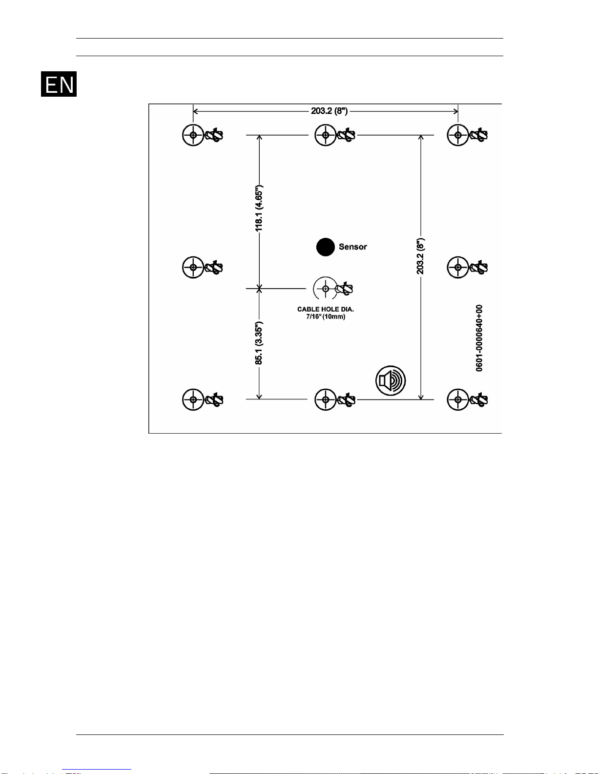
1. Determine an appropriate mounting position for the
reader.
2. Peel off the back of the self-stick mounting label template
included with the unit and place at the desired mounting
position. If you do not have the self-stick mounting
template label, refer to the Mounting Diagrams in this
manual for the dimensions. When mounting the reader, you
must remove the snap-off cover to access the screw holes -
see Figure 1. Installing the unit on metal surfaces will
reduce the read range considerably. to decrease the affect
of the metal surface use the BOSCH ARD-MPZ02 spacer
(sold separately) as described in Figure 2 for a max range
of 17 inch (43 cm).
3. Using the template as a guide, drill the holes (hole size is
indicated on mounting template) for mounting the reader
or spacer to the surface.
4. Drill a 7/16" (10 mm) hole for the cable. If mounting on
metal, place a grommet or electrical tape around the edge
of the hole and use the ARD-MPZ02 spacer.
5. Route the interface cable from the reader to the controller.
A linear type power supply is recommended

6en | Installation Manual ARD-AYZ12
| V 1.2 | 2009.09 Bosch Sicherheitssyteme GmbH
Figure 1 Removing the Top Cover
The figure obove shows the front view of the ARD-AYZ12 Long-
Range Reader.
When installing the reader, you must remove the snap-off cover
to access the screw holes. The reader must be mounted with
the appropriate screws (not supplied), as described in the
template provided.
Installing the unit on metal surfaces will reduce the read range
considerably, to decrease the affect of the metal surface use
BOSCH’s ARD-MPZ02 Spacer (sold separately) as described in
the image below for a max range of 43 cm (17 inch) - refer to
Figure 2.

ARD-AYZ12 Installation Manual | en 7
Bosch Sicherheitssyteme GmbH | V 1.2 | 2009.09
Figure 2 Installing the unit with the ARD-MPZ02 spacer
WIRING INSTRUCTIONS
The ARD-AYZ12 is supplied with an 18 inch (45 cm) pigtail,
having a 6-conductor cable.
To connect the reader to the controller, perform the following
steps:
1. Prepare the reader cable by cutting the cable jacket back
11/4 inches (3,4 cm) and strip the wires 1/2 inch (1,3 cm).
2. Prepare the controller cable by cutting the cable jacket
back 1 1/4 inches (3,4 cm) and strip the wires 1/2 inch
(1,3 cm).
3. Splice the reader pigtail wires to the corresponding
controller wires and cover each connection with insulating
tape.
4. If the tamper output is being utilized, connect the purple
wire to the correct input on the controller.
5. Trim and cover all conductors that are not used.

8en | Installation Manual ARD-AYZ12
| V 1.2 | 2009.09 Bosch Sicherheitssyteme GmbH
The table below shows how you should wire the reader to the
controller.
Cable Notes:
1. The individual wires coming out of the reader are color
coded according to the recommended Wiegand standard.
2. When using a separate power supply for the reader, this
supply and the controller's power supply must have a
common ground.
3. The cable shield wire on the reader should be attached to
an earth ground (best) or signal ground connection at the
panel or power supply end of the cable. This configuration
is best for shielding the reader cable from external
interference.
OPERATION INSTRUCTIONS
The reader should be tested after wiring it to a power supply
and the controller.
Do this by performing the following steps:
1. Power up the Reader. The LED flashes green on power up
(it may flash orange), and the Beeper sounds twice, at
which point it begins an auto-calibration procedure, this
can take up to two seconds, when the calibration is
complete a third beep will sound, thus indicating that the
Reader is working properly. The LED returns to its idle
state (red).
2. Present the appropriate type of proximity card to the
reader. The LED will momentarily flash green and a short
beep will be emitted. This indicates that the card was read
properly by the Proximity Card Reader.
3. After the card data is processed by the controller, the
controller can then turn the LED green. Refer to the
controller description of the LED operation if the reader
LED is controlled by the controller.
Color Wiegand Output
Red DC + Input
Black Ground
White Data 1
Green Data 0
Brown LED Control
Purple Tamper

ARD-AYZ12 Installation Manual | en 9
Bosch Sicherheitssyteme GmbH | V 1.2 | 2009.09
TECHNICAL SPECIFICATIONS
* Measured using Bosch Proximity Card (P/N ACD-ATR11ISO) or
equivalent. Range also depends on electrical environment and/
or proximity to metal.
Suitable for Outdoor Use
Electrical Characteristics
Power Supply Type Linear type recommended
Operating Voltage Range 10 - 16 VDC
Absolute Maximum (non-
operating)
18 VDC
Maximum Input Current Standby: 280 mA
Read: 330 mA
Tamper Output Open collector, active low, max
sink current 30 mA
Max Cable Distance to
Controller
500 ft. (150 meters)
Output modulation 26-bit Wiegand
Card read distance* 23.6 inch (60 cm)
Environmental Characteristics
Operating Temp. Range -22°F to 145°F (-30°C to 63°C )
Operating Humidity 0 to 95% (non condensing)
Environment class IP 54
Dimensions
Height x Width X Depth 11.81 x 11.81 x 1.0 inch
(300 x 300 x 25.4 mm)
Weight 2.35 Lbs. (1066 g)

10 en | Installation Manual ARD-AYZ12
| V 1.2 | 2009.09 Bosch Sicherheitssyteme GmbH
MOUNTING DIAGRAM

ARD-AYZ12 Installationshandbuch | de 11
Bosch Sicherheitssyteme GmbH | V 1.2 | 2009.09
Installationshandbuch
Dieses Installationshandbuch enthält folgende Informationen:
-Montageanleitung
- Verkabelungsanleitung
- Bedienungsanleitung
-TechnischeDaten
MONTAGEANLEITUNG
Montagesatz
Im Montagesatz sind folgende Komponenten für die Montage
enthalten:
- Eine Montageschablone
- Vier Flachkopfschrauben und Wanddübel
- Ein L-förmiges Werkzeug für Sicherheitsschrauben
- Drei Sicherheitsschrauben
Montieren Sie den Leser wie auf der Schablone angegeben mit
den entsprechenden Schrauben (nicht im Lieferumfang
enthalten).
Gehen Sie zur Montage des Lesers wie folgt vor:
1. Legen Sie eine geeignete Montageposition für den Leser
fest.
2. Ziehen Sie die Rückseite der mit dem Gerät mitgelieferten
selbstklebenden Montagemarkierungsschablone ab, und
bringen Sie die Schablone an der gewünschten
Montageposition an. Wenn Sie über keine selbstklebende
Montagemarkierungsschablone verfügen, können Sie die
Abmessungen aus den Montagedarstellungen in diesem
Handbuch entnehmen. Bei der Montage des Lesers muss
für den Zugang zu den Schraubenöffnungen die
Schnappabdeckung entfernt werden (siehe Bild 3). Wenn
das Gerät auf Metalloberflächen montiert wird, verringert
sich die Lesereichweite erheblich. Mit dem separat
angebotenen BOSCH ARD-MPZ02 Distanzstück (siehe
Bild 4) wird die Wirkung der Metalloberfläche verringert
und eine maximale Reichweite von 43 cm erreicht.
3. Bohren Sie die Löcher (der Bohrungsdurchmesser ist auf
der Montageschablone angegeben) für die Montage des
Lesers bzw. des Distanzstücks auf der entsprechenden
Oberfläche.
4. Bohren Sie ein Loch mit 10 mm Durchmesser für das Kabel.
Bei der Montage auf Metall ist die Bohrungskante mit einer
Schutzmanschette oder mit Isolierband zu versehen und
das ARD-MPZ02 Distanzstück zu verwenden.

12 de | Installationshandbuch ARD-AYZ12
| V 1.2 | 2009.09 Bosch Sicherheitssyteme GmbH
5. Führen Sie das Schnittstellenkabel vom Leser zum
Kontroller. Es wird empfohlen, ein Netzteil mit linearer
Spannungsregelung zu verwenden.
Bild 3 Entfernen der oberen Abdeckung
Die Abbildung oben zeigt die Vorderansicht des ARD-AYZ12
Lesers mit großer Reichweite.
Bei der Montage des Lesers muss für den Zugang zu den
Schraubenöffnungen die Schnappabdeckung entfernt werden.
Der Leser muss mit den entsprechenden Schrauben (nicht im
Lieferumfang enthalten) wie auf der mitgelieferten Schablone
angegeben montiert werden.
Wenn das Gerät auf Metalloberflächen montiert wird, verringert
sich die Lesereichweite erheblich. Mit dem separat
angebotenen BOSCH ARD-MPZ02 Distanzstück (siehe
Abbildung unten) wird die Wirkung der Metalloberfläche
verringert und eine maximale Reichweite von 43 cm erreicht
(siehe Bild 4).

ARD-AYZ12 Installationshandbuch | de 13
Bosch Sicherheitssyteme GmbH | V 1.2 | 2009.09
Bild 4 Installieren des Geräts mit dem ARD-MPZ02 Distanzstück
VERKABELUNGSANLEITUNG
Der ARD-AYZ12 wird mit einem 45 cm langen 6-adrigen
Anschlusskabel geliefert.
Gehen Sie zum Anschließen des Lesers an den Kontroller wie
folgt vor:
1. Bereiten Sie das Leser-Kabel vor, indem Sie den
Kabelmantel auf einer Länge von 3,4 cm entfernen und die
Drähte auf einer Länge von 1,3 cm abisolieren.
2. Bereiten Sie das Kontroller-Kabel vor, indem Sie den
Kabelmantel auf einer Länge von 3,4 cm entfernen und die
Drähte auf einer Länge von 1,3 cm abisolieren.
3. Verbinden Sie die Drähte der Anschlussleitung des Lesers
mit den entsprechenden Drähten des Controller-Kabels,
und isolieren Sie alle Verbindungsstellen mit Isolierband.
4. Wenn der Sabotageausgang verwendet wird, schließen Sie
den violetten Draht an den entsprechenden Eingang am
Controller an.

14 de | Installationshandbuch ARD-AYZ12
| V 1.2 | 2009.09 Bosch Sicherheitssyteme GmbH
5. Schneiden Sie alle nicht verwendeten Leiter zurück, und
isolieren Sie sie entsprechend.
In der nachfolgenden Tabelle ist die Verdrahtung des Lesers mit
dem Kontroller angegeben.
Hinweise zur Verkabelung:
1. Die einzelnen Adern des Lesers sind nach dem
empfohlenen Wiegand-Standard farbcodiert.
2. Bei Verwendung eines separaten Netzteils für den Leser
muss für dieses Netzteil und das Netzteil des Kontrollers
eine gemeinsame Masse vorhanden sein.
3. Die Abschirmung ist an einen Erdanschluss (optimale
Lösung) bzw. Erdleiter am Panel oder auf der Netzteilseite
des Kabels anzuschließen. Diese Konfiguration ist für die
Abschirmung des Leser-Kabels gegen externe Störungen
die beste Lösung.
BEDIENUNGSANLEITUNG
Nach der Verkabelung mit einem Netzteil und dem Kontroller ist
die Funktion des Lesers zu überprüfen.
Gehen Sie dabei wie folgt vor:
1. Schalten Sie den Leser ein. Die LED blinkt nach dem
Einschalten grün (evtl. auch orange), und der akustische
Signalgeber ertönt zweimal. Danach wird mit der
automatischen Kalibrierung begonnen. Dieser Vorgang
kann bis zu zwei Sekunden dauern. Wenn die Kalibrierung
abgeschlossen ist, ertönt ein dritter Signalton, der die
ordnungsgemäße Funktion des Lesers signalisiert. Die LED
signalisiert wieder den inaktiven Zustand (rot).
2. Lesen Sie den entsprechenden berührungslosen
Ausweistyp mit dem Leser ein. Die LED blinkt kurz grün,
und es ertönt ein kurzes akustisches Signal. Damit wird
angezeigt, dass die Karte ordnungsgemäß vom
Farbe Wiegand-Ausgang
Rot DC+-Eingang
Schwarz Masse
Weiß Daten 1
Grün Daten 0
Braun LED-Steuerung
Violett Sabotage

ARD-AYZ12 Installationshandbuch | de 15
Bosch Sicherheitssyteme GmbH | V 1.2 | 2009.09
berührungslosen Ausweisleser gelesen wurde.
3. Nachdem die Kartendaten vom Kontroller verarbeitet
worden sind, wird die LED vom Kontroller auf grün
geschaltet. Wenn die LED des Lesers vom Kontroller
gesteuert wird, finden Sie entsprechende Hinweise in der
Kontroller-Beschreibung für den LED-Betrieb.

16 de | Installationshandbuch ARD-AYZ12
| V 1.2 | 2009.09 Bosch Sicherheitssyteme GmbH
TECHNISCHE DATEN
* Gemessen mit Bosch berührungslosem Ausweis (Artikelnr.
ACD-ATR11ISO) oder einer gleichwertigen Komponente. Die
Reichweite hängt auch von der elektrischen Umgebung und/
oder der Nähe zu Metall ab.
Für die Verwendung im Freien geeignet
Elektrische Kenndaten
Netzteiltyp Linear (empfohlen)
Betriebsspannungsberei
ch
10 – 16 VDC
Absolutes Maximum
(Gerät nicht in Betrieb)
18 VDC
Maximaler
Eingangsstrom
Standby: 280 mA
Lesen: 330 mA
Sabotageausgang Open Collector, low-aktiv,
maximaler Ausgangsstrom 30 mA
Max. Kabellänge bis zum
Kontroller
150 m
Ausgangsmodulation 26-Bit-Wiegand
Kartenleseabstand* 60 cm
Umgebungskenndaten
Betriebstemperaturberei
ch
-30 °C bis 63 °C
Luftfeuchtigkeit während
des Betriebs
0 bis 95 % (nicht kondensierend)
Schutzart IP 54
Abmessungen
Höhe x Breite x Tiefe
300 x 300 x 25,4 mm
Gewicht 1066 g

ARD-AYZ12 Installationshandbuch | de 17
Bosch Sicherheitssyteme GmbH | V 1.2 | 2009.09
MONTAGEDARSTELLUNG

18 de | Installationshandbuch ARD-AYZ12
| V 1.2 | 2009.09 Bosch Sicherheitssyteme GmbH

ARD-AYZ12 安装手册 | zh 19
Bosch Sicherheitssyteme GmbH | V 1.2 | 2009.09
安装手册
本安装手册介绍以下内容:
-安装说明
-布线说明
-操作说明
-技术规格
安装说明
安装套件
安装套件包括下列在安装过程中用到的物品:
- 一块安装模板
- 四个盘头螺丝和墙壁插头
- 一个 L 形防拆卸螺丝工具
- 三枚防拆卸螺丝
按照模板所示使用适当的螺丝 (不提供)安装读卡器。
要安装读卡器,请执行下列步骤:
1. 确定读卡器的适当安装位置。
2. 去掉装置随附的自粘安装模板标签的背面,然后放在适当的安装
位置。 如果您没有自粘安装模板标签,请参考本手册中的安装
图,了解相关尺寸。 当安装读卡器时,必须拆除卡盖才能露出螺
孔 - 参见
图 5
。 在金属表面上安装本装置时,将会显著缩短读卡
器的读取距离。 为减小金属表面的影响,请按照
图 6
中的说明安
装 BOSCH ARD-MPZ02 隔块 (单独销售),这可实现长达 17
英寸 (43 厘米)的读取距离。
3. 参照模板,钻取用于将读卡器或隔块固定到安装表面的孔 (孔
尺寸参见安装模板)。
4. 钻取一个 7/16 英寸 (10 毫米)的电缆孔。 如果安装在金属表面
上,请在孔周边放置孔环或绝缘胶带,然后使用 ARD-MPZ02 隔
块。
5. 将接口电缆从读卡器连接到控制器。 推荐使用线性电源。

20 zh | 安装手册 ARD-AYZ12
| V 1.2 | 2009.09 Bosch Sicherheitssyteme GmbH
图5 拆除顶盖
上图显示了 ARD-AYZ12 长距离读卡器的前视图。
当安装读卡器时,必须拆除卡盖才能露出螺孔。 读卡器必须按照随附
的模板所示,使用适当的螺丝 (不提供)加以安装。
在金属表面上安装本装置时,将会显著缩短读卡器的读取距离。为减
小金属表面的影响,请按照下图所示使用博世的 ARD-MPZ02 隔块
(单独销售),这可实现长达 17 英寸 (43 厘米)的读取距离 - 参见
图 6
。
Table of contents
Languages:
Other Bosch Scanner manuals

Bosch
Bosch OBD 2220 INFO SCAN User manual

Bosch
Bosch GMS 120 Professional User manual

Bosch
Bosch MD-200 User manual

Bosch
Bosch OBD1300 User manual

Bosch
Bosch BEA 460 User guide

Bosch
Bosch D-tect 120 Professional User manual

Bosch
Bosch D-TECT 100 User manual

Bosch
Bosch XA1504A5HW User manual

Bosch
Bosch ADS 625X User manual

Bosch
Bosch OBD1110 User manual