manuals.online logo
Brands
  1. Home
  2. •
  3. Brands
  4. •
  5. Bosch
  6. •
  7. Security Sensor
  8. •
  9. Bosch FAA-500 User manual

Bosch FAA-500 User manual

Installationshinweis / Installation Instructions
FAA-500, FAA-500-R - Meldersockel / Detector bases
610-F.01U.000.615 / A2
de/en/fr/it/es/pt/nl/tr
ST/PMF/zab
1 / 4
45
6
1
2
3
MPA
BMZ /
FACP
+V
0V
LSN a1/a2
LSN b1 ws/w
nächster Melder/ next detector
ws/w
gn/g
rt/r rt/r
sw/bk sw/bk
ge/y
ge/y
b2
FAA-500(-R)
MPA = Melderparallelanzeige/Remote Fire Alarm Display
nicht beim Relaissockel / not for relay bases
gn/g
(7) Feder für Meldereinbau in Zwischendecken
Bei Meldereinbau in Beton- oder Holzdecken muss die
Spezialfeder FAA-500-SPRING (Sachnr. F.01U510.028,
Liefereinheit 10 Stck., rote Markierung) eingesetzt werden.
(7) Spring for detector mounting in false ceiling panels
For concrete and wooden ceilings, replace with
FAA-500-SPRING (part nr. F.01U510.028, delivery unit
10 pcs., red marking).
7
(7) Spring for detector mounting in false ceiling panels
For concrete and wooden ceilings, replace with
FAA-500-SPRING (part nr. F.01U510.028, delivery unit
10 pcs., red marking).
Deutsch
Anschaltung
Verdrahten Sie den Sockel LSN gemäß der Beschriftung im
äußeren Ring (2), (innerer Ring: GLT-Sockel).
.Die Halterungen für Kabelbinder (1) können zum
Fixieren des Sockels während des Verdrahtens genutzt
werden.
Anschluss Klemme Draht
Spannung - * 0 V schwarz (sw)
Spannung + * + V rot (rt)
LSN a in/out a1/a2 weiß (ws)
LSN b in b1 gelb (ge)
LSN b out b2 gelb (ge)
Indikatorausgang c
Abschirmung (grün [gn])
Relaisa sgänge
NO
Relaisausgänge
(FAA
-
500
-
R)
NC
(FAA
-
500
-
R)
COM
* Klemmen zum Durchschleifen der Versorgungsspan-
nung für andere LSN-Elemente
Montage
1. Setzen Sie den Sockel so in die Hohlraumdose ein, dass
die dreieckige Markierung am Außenrand der Hohlraum-
dose (4) mit der einfachen Führungsnut (5) am Sockel
übereinstimmt.
2. Drehen Sie den Sockel, bis die Befestigungsschrauben
in der Mitte der Langschlitze (6) sind.
3. Justieren Sie die Sockel um diese Position, bis sie in ei-
ner Linie erscheinen.
4. Drehen Sie die vier Schrauben fest.
English
Wiring
Wire the LSN bases according to the lettering on the outer
ring (2), (inner ring: conventional technology).
.During cabling, the holders for cable ties (1) can be used to
fix the base.
Connection Terminal Wire
Voltage - * 0 V black (bk)
Voltage + * + V red (r)
LSN a in/out a1/a2 white (w)
LSN b in b1 yellow (y)
LSN b out b2 yellow (y)
Indicator output c
Shielding green (g)
Rela
NO
Relay
(FAA
-
500
-
R)
NC
(FAA
-
500
-
R)
COM
* Terminals for interconnecting all bases with voltage
supply for other LSN elements
Mounting
1. Place the base in the ceiling mount back box so that the
triangular mark (4) on the outer rim of the back box
matches with the single guideway (5).
2. Turn the base until the fastening screws are in the middle
of the long slit (6).
3. Slightly turn each base until the bases align in one direc-
tion.
4. Tighten the four screws.
Technische Daten / Technical Data
Meldersockeltyp / Base type FAA-500 FAA-500-R
Stromaufnahme / Current consumption -0,2 mA
Relaiskontakt-Belastbarkeit / Contact load -1 A, 30 V DC
Kabelquerschnitt / Wire gauge 0,3 mm2- 3,3 mm2(22 AWG - 12 AWG)
Sachnummer / Part number 4.998.151.297 4.998.151.299
BOSCH Sicherheitssysteme GmbH
Robert-Koch-Str. 100
D-85521 Ottobrunn
[email protected]
www.boschsecuritysystems.com
Instruction de mise en place / Avviso d’Installazione
FAA-500, FAA-500-R - Socles de détecteur / Basi rivelatore
610-F.01U.000.615 / A2
de/en/fr/it/es/pt/nl/tr
ST/PMF/zab
2/ 4
45
6
1
2
3
MPA
FACP /
FACP
+V
0V
LSN a1/a2
LSN b1 b/b
détecteur suivant / prossimo sensore
b/b
v/v
r/r r/r
n/n n/n
j/g
j/g
FAA-500(-R)
MPA = Affichage d’alarme incendie à distance
(pas pour le socle à relais)/
Indicatore in parallelo di sensore
(non per base relè)
v/v
7
(7) Ressort pour montage du détecteur dans des panneaux
de faux plafonds
Pour les plafonds en béton et en bois, utilisez plutôt le
Ressort FAA-500 (réf. F.01U510.028, livraison par 10 pcs.,
marquage rouge).
(7) Elemento di fissaggio per il montaggio del rivelatore sui
pannelli di un falso soffitto
In caso di soffitti in cemento e in legno, sostituire con l’elemento
di fissaggio FAA-500 (N. prodotto F.01U510.028, unità di
fornitura da 10 pz., contrassegno rosso).
Français
Câblage
Procédez au câblage des socles LSN en fonction des indica-
tions sur la bague extérieure (2), (bague intérieure : technologie
traditionnelle).
.Pendant le câblage, vous pouvez utiliser les supports
des attaches de câbles (1) pour fixer le socle.
Connexion Borne Fil
Tension - * 0 V noir (n)
Tension + * + V rouge (r)
Entrée/sortie LSN a a1/a2 blanc (b)
Entrée LSN b b1 jaune (j)
Sortie LSN b b2 jaune (j)
Sortie d’indicateur c
Blindage vert (v)
Relais
NO
Relais
(FAA
-
500
-
R)
NF
(FAA
-
500
-
R)
COM
* Bornes d’interconnexion de tous les socles avec ali-
mentation en tension pour autres éléments LSN
Montage
1. Placez le socle dans le boîtier arrière pour montage au
plafond de manière à ce que le repère triangulaire (4) sur
le bord extérieur du boîtier arrière coïncide avec la rai-
nure de guidage unique (5).
2. Tournez le socle jusqu’à ce que les vis de fixation se
trouvent au centre de la longue fente (6).
3. Tournez légèrement chaque socle jusqu’à ce que tous
les socles soient alignés dans le même sens.
4. Serrez les quatre vis.
Italiano
Cablaggio
Cablare le basi LSN secondo le indicazioni delle lettere sull’a-
nello esterno (2), (anello interno: tecnologia tradizionale).
.Durante il cablaggio, il supporto per le fascette fermacavi
(1) può essere utilizzato per fissare la base.
Connessione Terminale Cavo
Tensione - * 0 V nero (n)
Tensione + * + V rosso (r)
LSN a in/out a1/a2 bianco (b)
LSN b in b1 giallo (g)
LSN b out b2 giallo (g)
Uscita indicatore c
Shielding verde (v)
Relè
NO
Relè
(FAA
-
500
-
R)
NC
(FAA
-
500
-
R)
COM
* Terminali per l’interconnessione di tutte le basi per l’ali-
mentazione di altri elementi LSN.
Montaggio
1. Posizionare la scatola a incasso in modo che il contras-
segno triangolare (4) sul margine esterno della scatola a
incasso corrisponda alla scanalatura della guida.
2. Ruotare la base finché le viti di fissaggio non si trovano
al centro della scanalatura lunga (6).
3. Ruotare leggermente ogni base fino ad allinearle in una
direzione.
4. Stringere le quattro viti.
Données techniques / Dati tecnici
Type de socle / Tipo base FAA-500 FAA-500-R
Consommation de courant / Consumo di corrente -0,2 mA
Charge des contacts / Carico contatto -1 A, 30 V c.c. / DC
Section des câbles / Diametro del cavo 0,3 mm2- 3,3 mm2(22 AWG - 12 AWG)
Code produit / Codice Prodotto 4.998.151.297 4.998.151.299
Instrucciones de instalación / Instruções de montagem
FAA-500, FAA-500-R - Bases de detectores / Bases de detectores
3/ 4610-F.01U.000.615 / A2
de/en/fr/it/es/pt/nl/tr
ST/PMF/zab
1
2
3
MPA
FACP /
FACP
+V
0V
LSN a1/a2
LSN b1 b/w
siguiente detector / detector seguinte
b/w
v/g
r/r r/r
ng/bk ng/bk
a/y
a/y
FAA-500(-R)
MPA = Display de alarma de incendios remota
(no para la base del relé)/
display do alarme de incêndios remoto
(não é indicada para base de relé)
v/g
45
6
7
(7) Muelle para montar detectores en techos falsos
Para techos de hormigón y madera, sustituir con un muelle
FAA-500 (nº de pieza F.01U510.028, unidad de entrega
10 piezas, marcado en rojo).
(7) Mola para montar detectores em painéis de tectos falsos
No caso dos tectos de betão e de madeira, substitua pela
mola FAA-500 (ref.ª F.01U510.028, embal. de 10 unids.,
marca vermelha).
Español
Cableado
Cablearlas bases LSN de acuerdo con las letras en al aro exterior (2),
(aro interior: tecnología convencional).
.Durante el cableado, se pueden utilizar los sujetadores para los
soportes de cables (1) para fijar la base.
Conexión Terminal Cable
Voltaje - * 0 V negro (ng)
Voltaje + * + V rojo (r)
LSN a entrada/salida a1/a2 blanco (b)
LSN b entrada b1 amarillo (a)
LSN b salida b2 amarillo (a)
Indicador salida c
Protección verde (v)
Relé
NO
Relé
(FAA
-
500
-
R)
NC
(FAA
-
500
-
R)
COM
* Terminales para interconectar todas las bases con
suministro de voltaje para otros elementos LSN
Montaje
1. Colocar la base en la caja posterior para montaje en el te-
cho de tal manera que la marca triangular (4) en el borde
exterior de la caja posterior coincida con la guía única (5).
2. Girar la base hasta que los tornillos de sujeción se en-
cuentren en el centro de la ranura larga (6).
3. Girar cada base ligeramente hasta que las bases se ali-
neen en una sola dirección.
4. Apretar los cuatro tornillos.
Português
Cablagem
Ligue os cabos das bases LSN de acordo com as inscrições
do anel exterior (2), (anel interior: tecnologia convencional).
.Os suportes das braçadeiras para cabos (1) podem ser
usados para fixar a base durante a ligação dos cabos.
Ligação Terminal Cabo
Tensão - * 0 V preto (bk)
Tensão + * + V vermelho (r)
LSN a in/out a1/a2 branco (w)
LSN b in b1 amarelo (y)
LSN b out b2 amarelo (y)
Saída do indicador c
Blindagem verde (g)
Relé
NO
Relé
(FAA
-
500
-
R)
NC
(FAA
-
500
-
R)
COM
* Terminais para alimentar todas as bases com tensão,
para outros elementos LSN
Montagem
1. Coloque a base na caixa de embutir para tecto, de forma
a que a marca triangular (4) no rebordo exterior da caixa
de embutir fique alinhada com a ranhura simples (5).
2. Rode a base até os parafusos ficarem centrados na
fenda longitudinal (6).
3. Rode ligeiramente cada uma das bases até ficarem alin-
hadas num só sentido.
4. Aperte os quatro parafusos.
Datos técnicos / Características técnicas
Tipo de base / Tipo de base FAA-500 FAA-500-R
Consumo de corriente / Consumo de corrente -0,2 mA
Carga de contacto / Potência do relé -1 A, 30 V DC
Calibrador de alambres / Secção do cabo 0,3 mm2- 3,3 mm2(22 AWG - 12 AWG)
Código de producto / Identificação do produto 4.998.151.297 4.998.151.299
Installatievoorschrift/ Montaj Talimatlarý
FAA-500, FAA-500-R - Detectorsokkels / Detektör kaideleri
4/ 4610-F.01U.000.615 / A2
de/en/fr/it/es/pt/nl/tr
ST/PMF/zab
1
2
3
MPA
FACP /
FACP
+V
0V
LSN a1/a2
LSN b1 w/w
volgende detector / sonraki detektör
w/w
gr/g
r/r r/r
zw/bk zw/bk
ge/y
ge/y
FAA-500(-R)
MPA = nevenindicator (niet voor relaissokkel)/
Uzaktan Yangýn Alarmý Göstergesi
(röle kaidesi için deðildir)
gr/g
45
6
7
(7) Veer voor montage van een detector in plafondpanelen
van een verlaagd plafond
Voor betonnen en houten plafonds, vervangen met
FAA-500-SPRING (onderdeelnr. F.01U510.028,
leveringseenheid 10 stuks, rode markering).
(7) Detektörün yalancý tavan panellerine montaj için yay
Betonarme ve ahþap tavanlar için, FAA−500−YAY (parça no.
F.01U510.028, teslimat 10 adet, kýrmýzý iþaretli) ile deðiþtirin.
Nederlands
Bedrading
Bedraad de LSN-sokkels volgens de letters op de buitenring
(2), (binnenring: conventionele technologie).
.Tijdens het bedraden kunnen de houders voor
kabelbinders (1) worden gebruikt om de sokkel vast te
zetten.
Aansluiting Klem Draad
Spanning - * 0 V zwart (zw)
Spanning + * + V rood (r)
LSN a in/out a1/a2 wit (w)
LSN b in b1 geel (ge)
LSN b out b2 geel (ge)
Indicatoruitgang c
Afscherming groen (gr)
Relais
NO
Relais
(FAA
-
500
-
R)
NC
(FAA
-
500
-
R)
COM
* Klemmen om alle sokkels door te verbinden met de
spanningsbron voor andere LSN elementen
Montage
1. Plaats de sokkel zo in de inbouwdoos voor plafondmon-
tage dat de driehoekige markering (4) op de buitenrand
van de inbouwdoos aansluit op de enkele inkeping (5).
2. Draai de sokkel zo dat de bevestigingsschroeven zich in
het midden van de lange inkeping (6) bevinden.
3. Draai elke sokkel totdat de sokkels in één richting zijn uit-
gericht.
4. Draai de vier schroeven vast.
Türkçe
Kablo Baðlantýsý
LSN kaidelerinin kablo baðlantýsýný, dýþ halka (2) üzerindeki har−
flere göre yapýn, (iç halka: eski teknoloji).
.Kablo baðlantýsý sýrasýnda, kaideyi sabitlemek için kablo
baðlarýnýn (1) tutucularý kullanýlabilir.
Baðlantý Terminal Kablo
Gerilim - * 0 V siyah (bk)
Gerilim + * + V kýrmýzý (r)
LSN a giriþ/çýkýs a1/a2 beyaz (w)
LSN b giriþ b1 sarý (y)
LSN b çikis b2 sarý (y)
Gösterge çýkýsý c
Ekranlama yeþil (g)
Röl
NA
Röle
(FAA
−
500
−
R)
NK
(FAA
−
500
−
R)
COM
* Baska LSN elemanlarý için tüm kaidelere gerilim beslemesi
baðlamak için kullanýlan terminaller
Montaj
1. Kaideyi, sýrtlýðýn dýs kenarýndaki üç gen isaret (4), tekli kýlavuz
(5) ile ayný hizaya gelecek þekilde tavan montaj sýrtlýðýna yer−
lestirin.
2. Tespit vidalarý, uzun girintinin (6) ortasýna gelene kadar kai−
deyi çevirin.
3. Kaideler tek yönde hizalanana kadar her bir kaideyi hafifçe
çevirin.
4. Dört vidayý sýkýn.
Technische gegevens / Teknik veriler
Sokkeltype / Kaide Tipi FAA-500 FAA-500-R
Stroomverbruik / Akim tüketimi -0,2 mA
Contactbelasting / Kontak yükü -1 A, 30 V DC
Draaddikte / Kablo boyutlarý 0,3 mm2- 3,3 mm2(22 AWG - 12 AWG)
Product-ID / Ürün Kodu 4.998.151.297 4.998.151.299
This manual suits for next models

1

Other Bosch Security Sensor manuals

Bosch FCP-O 500 User manual

Bosch

Bosch FCP-O 500 User manual

Bosch FMC-210-SM-G-R User manual

Bosch

Bosch FMC-210-SM-G-R User manual

Bosch PAVIRO Series User manual

Bosch

Bosch PAVIRO Series User manual

Bosch ISC-PDL1-W18H User manual

Bosch

Bosch ISC-PDL1-W18H User manual

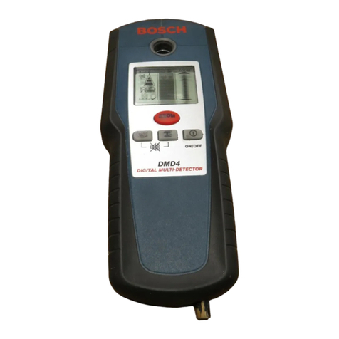
Bosch Multi-Detector DMD4 Assembly instructions

Bosch

Bosch Multi-Detector DMD4 Assembly instructions

Bosch ISN?SM?80 User manual

Bosch

Bosch ISN?SM?80 User manual

Bosch ISC-PDL1-WC30G User manual

Bosch

Bosch ISC-PDL1-WC30G User manual

Bosch DS938Z User manual

Bosch

Bosch DS938Z User manual

Bosch Blue Line Q1 User manual

Bosch

Bosch Blue Line Q1 User manual

Bosch DS820i Series User manual

Bosch

Bosch DS820i Series User manual

Bosch Professional Series User manual

Bosch

Bosch Professional Series User manual

Bosch ISC-SM-90 User manual

Bosch

Bosch ISC-SM-90 User manual

Bosch TriTech DS950 Series User manual

Bosch

Bosch TriTech DS950 Series User manual

Bosch TriTech+ Professional ISC-PDL1-WAC30G User manual

Bosch

Bosch TriTech+ Professional ISC-PDL1-WAC30G User manual

Bosch ISP-PPR1-WA16K User manual

Bosch

Bosch ISP-PPR1-WA16K User manual

Bosch DS1109i User manual

Bosch

Bosch DS1109i User manual

Bosch ISM-BLD1 User manual

Bosch

Bosch ISM-BLD1 User manual

Bosch Blue Line P1 User manual

Bosch

Bosch Blue Line P1 User manual

Bosch DS940Q User manual

Bosch

Bosch DS940Q User manual

Bosch ISC-CDL1-W15G User manual

Bosch

Bosch ISC-CDL1-W15G User manual

Bosch DS940P User manual

Bosch

Bosch DS940P User manual

Bosch DS820i Series User manual

Bosch

Bosch DS820i Series User manual

Bosch BMA400 Instruction Manual

Bosch

Bosch BMA400 Instruction Manual

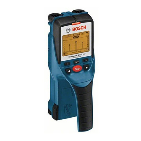
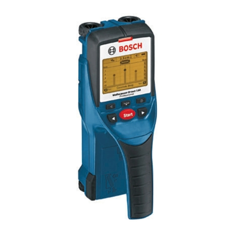
Bosch D-tect 150 Professional User manual

Bosch

Bosch D-tect 150 Professional User manual

Popular Security Sensor manuals by other brands

EsiWelma Sensigas URS20SE manual

EsiWelma

EsiWelma Sensigas URS20SE manual

Protrol IPC4020 user manual

Protrol

Protrol IPC4020 user manual

Wavetronix SmartSensor HD user guide

Wavetronix

Wavetronix SmartSensor HD user guide

Kidde KI-PHD Installation sheet

Kidde

Kidde KI-PHD Installation sheet

Elkron VSD3 installation manual

Elkron

Elkron VSD3 installation manual

Sperian ToxiPro Reference manual

Sperian

Sperian ToxiPro Reference manual

Risco WL T6S installation instructions

Risco

Risco WL T6S installation instructions

WAGNER TITANUS RACK-SENS 1U Technical manual

WAGNER

WAGNER TITANUS RACK-SENS 1U Technical manual

System Sensor B501A Installation and maintenance instructions

System Sensor

System Sensor B501A Installation and maintenance instructions

Mhouse MAD5 Instructions for installation

Mhouse

Mhouse MAD5 Instructions for installation

Rielta FOTON-SH2-RK installation guide

Rielta

Rielta FOTON-SH2-RK installation guide

Uniden R9 user manual

Uniden

Uniden R9 user manual

SCS Sentinel KA-SA03 user manual

SCS Sentinel

SCS Sentinel KA-SA03 user manual

Siemens L-852A-D Dualite manual

Siemens

Siemens L-852A-D Dualite manual

Linde G-TECTA 4G operating manual

Linde

Linde G-TECTA 4G operating manual

Clas Ohlson 36-2285 quick start guide

Clas Ohlson

Clas Ohlson 36-2285 quick start guide

iRay Technology Mars1417VS user manual

iRay Technology

iRay Technology Mars1417VS user manual

Mace 80200 manual

Mace

Mace 80200 manual

manuals.online logo
manuals.online logoBrands
  • About & Mission
  • Contact us
  • Privacy Policy
  • Terms and Conditions

Copyright 2025 Manuals.Online. All Rights Reserved.