Bosch RF1100E User manual

EN
Installation Instructions
Wireless Glass Break
Transmitter
RF1100E

RF1100E | Installation Instructions | Trademarks
2 Bosch Security Systems | 6/04 | 4998138687C
Trademarks
Duracell®is a registered trademark of The Gillette Company.
Eveready™ is a trademark of Eveready Battery Company, Inc.
Panasonic®is a registered trademark of Matsushita Electric Industrial Co., Ltd.
Figure 1: RF1100E Mounting Template (Actual size)
3
2 2
1
1 - Wall tamper screw (optional) 2 - Mounting screw 3 - Base of RF1100E

RF1100E |Installation Instructions | 1.0 Overview
.
Bosch Security Systems | 6/04 | 4998138687C 3
1.0 Overview
The RF1100E Wireless Glass Break Transmitter is a
wireless transmitter used for detecting breaking glass. It
has two tamper switches: a cover and wall (optional). If
the control panel is programmed to receive tamper
events, activating either switch sends a notification to
the control panel.
Radio frequency (RF) supervision is provided by
transmitting a signal to the receiver every 15 min if
there is no alarm activity. All transmissions from the
RF1100E send battery status information.
2.0 Installation Considerations
Mount the RF1100E on flat surfaces, such as ceilings
and walls. Mount the unit to optimize glass break
detection. Refer to Figure 2 and Figure 3 for mounting
examples.
In normal residential or commercial applications,
locate the RF1100E within 100 m of its assigned
receiver.
For best detector performance, select a
mounting location that is:
• within 7.6 m of the protected glass
• within clear view of the protected
glass (there is no minimum range)
• at least 2 m from the floor
• at least 1 m from forced-air ducts
• at least 1 m from sirens or bells
greater than 5 cm in diameter
• on a window frame if any heavy
window covering is present
Avoid mounting the detector:
• in a corner
• on the same wall as the protected
glass
• on free-standing posts or pillars
• in rooms with noisy equipment such as
air compressors, bells, and power tools
Test the detector in the desired mounting
location before drilling mounting holes.
Refer to Section 3.2 Testing on page 5.
The RF1100E’s maximum outside RF range is
approximately 300 m.
Figure 2: Wall Mounting Locations (top view)
7
5
1
24
3
6
3
3
1 - Poor location -
fully opened door
can block
detector’s range3
2 - Poor location -
high risk of door
slam noise3
3 - 7.6 m maximum
mounting distance
4 - Window
5 - Best locations1
6 - Satisfactory
location2
7 - Satisfactory
location if a heavy
window covering
is present2
Figure 3: Ceiling Mounting Locations (side view)
1
4
3
5
2
1 - Best
locations1
2 - Ceiling
3 - 7.6 m maximum
mounting distance
4 - Glass
5 - Floor
1 Best location: where the RF1100E is most effective.
2 Satisfactory location: where the effectiveness of the RF1100E may
be reduced.
3 Poor location: where the effectiveness of the RF1100E is
impaired.

RF1100E | Installation Instructions | 3.0 Setup
4 Bosch Security Systems | 6/04 | 4998138687C
3.0 Setup
1. Carefully open the service door (Item 3 in Figure 4)
and insert the two AA batteries (supplied),
observing the correct polarity.
2. Select a mounting location (refer to Section 2.0
Installation Considerations on page 3).
3. Temporarily mount the unit so you can remove it
as needed.
3.1 Sensitivity Setting
1. If the front housing is attached, carefully open the
service door (Item 4 in Figure 5).
2. Enable the LEDs for test purposes by sliding the
LED ENABLE switch (Item 5 in Figure 5) in the
direction the arrow points (above the switch). An
orange flag protrudes from the side of the
RF1100E.
Figure 4: RF1100E Front Layout
8
9
3
5
7
61
EVENT
4
2
1 - Service door tamper switch
2 - AA batteries
3 - Service Door
4 - SW4 test mode pads
5 - SW3 sensitivity DIP switches
6 - Alarm LED
7 - Event LED
8 - LED enable switch (off position)
9 - Housing screw
Figure 5: Sensitivity switch
EVENT
3
2
4
5
1
1 - SENS1
2 - Test pads
3 - SENS2
4 - Service door
5 - LED enable switch
(shown in the OFF
position)
3. Determine the sensitivity setting for your
application from Table 1.
Table 1: RF1100E Sensitivity Settings
Sensitivity SENS1 SENS2 Approximate Range
Maximum OFF OFF 7.6 m
Medium ON OFF 4.6 m
Low OFF ON 3 m
Lowest ON ON 1.5 m
4. Use a small screwdriver to move the sensitivity
switches. Use the settings determined in Step 3.
5. Turn on any sources of noise (such as machinery,
office, or audio equipment) in the area.
6. Observe the green event LED (Item 7 in Figure 8)
for approximately 1 min. If the green LED flashes,
relocate the unit or reduce the sensitivity by
adjusting the sensitivity switch.
7. Repeat Steps 3 through 6until you achieve the best
sensitivity level.
8. After setting the sensitivity, slide the LED enable
switch (Item 5 in Figure 5) to the OFF position.

RF1100E |Installation Instructions | 3.0 Setup
.
Bosch Security Systems | 6/04 | 4998138687C 5
3.2 Testing
Test the RF1100E at least once each year. Test the
detector with the 13-332 Sound Sensor Tester.
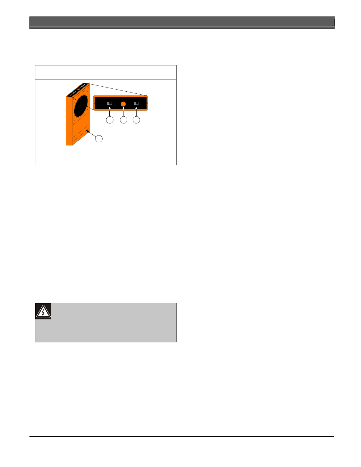
Figure 6: 13-332 Sound Sensor Tester
1
ACTIVATE TEST FLEX MAN
2 3 4
1 - 13-332
2 - Activate/Test switch
3 - Start button
4 - Flex/Man switch
3.2.1 Entering test mode
Place the RF1100E in Test Mode before you can test
the unit. In Test Mode, the RF1100E's LED disable
switch (Item 5 in Figure 5 on page 4) is overridden. You
can enter the Test Mode locally or remotely.
To enter the Test Mode locally:
1. Carefully open the service door of the RF1100E.
2. Insert a screwdriver into the slot next to the
sensitivity switches that contains the test pads.
3. Touch both test pads at the same time with the tip
of the screwdriver.
The green LED (Item 7 in Figure 8 on page 6) on the
RF1100E flashes once per second. If the green LED
does not flash, repeat Steps 2 and 3.
You can select the glass break sensitivity remotely from
a Bosch 13-332 Sound Sensor Tester to activate a test
mode.
The 13-332 Sound Sensor Tester
produces extremely loud sounds and can
be hazardous to hearing when used at
close range. Do not point the 13-332
towards someone’s head.
To enter the Test Mode remotely:
1. Stand within 3 m of the RF1100E.
2. Move the switches on top of the 13-332 tester to
ACTIVATE (Item 2 in Figure 6) and to MAN
(Item 4, Figure 6) modes.
3. Point the front of the tester towards the detector
and press the red Start button on top (refer to
Item 3 in Figure 6).
The tester buzzes and the green LED on the RF1100E
flashes once per second. If the green LED does not
flash, move closer to the detector and repeat the
procedure.
3.2.2 Testing the Detector (Flex and Audio
Signals)
1. Set the 13-332 tester switches to the TEST (Item 2
in Figure 6) and FLEX positions (Item 4 in Figure 6).
2. Press the red Start button (Item 3 in Figure 6). The
tester activates and starts an eight-second armed
period.
3. If window coverings are present, close them fully.
4. Hold the 13-332 tester near the point on the glass
farthest from the detector. If window coverings are
present, hold the tester between the glass and
window coverings.
5. Carefully strike the glass with a cushioned tool.
The 13-332 tester responds by producing a burst of
glass break audio.
If the RF1100E receives both the flex and audio signals
properly, its red Alarm LED lights for 3 sec.
If the red LED does not light, return to Step 2 in Section
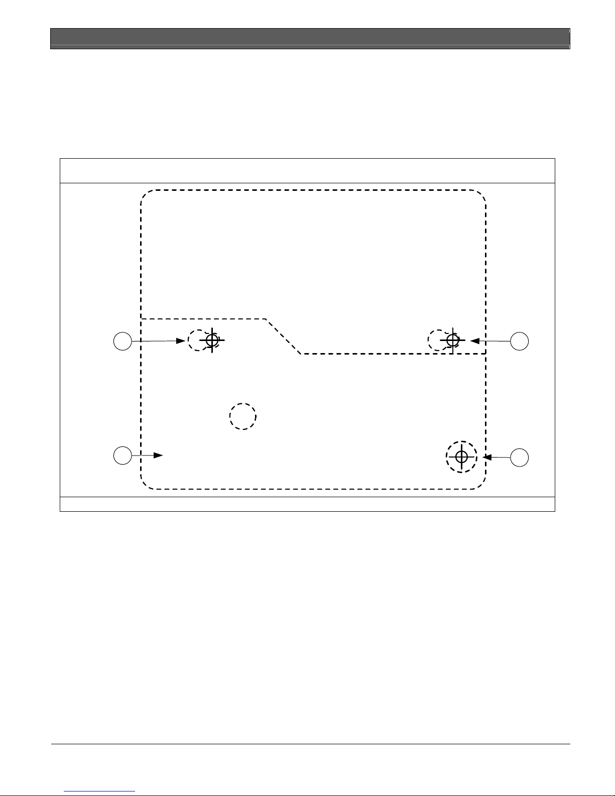
3.0 Setup on page 4 to reposition the detector.
3.2.3 Exiting Test Mode
To exit the Test Mode locally:
1. Carefully open the service door of the RF1100E.
2. Insert a screwdriver into the slot next to the
sensitivity switches that contains the test pads.
3. Touch both test pads at the same time with the tip
of the screwdriver.
When the detector exits Test Mode, the green LED
(Item 7 in Figure 8) on the RF1100E stops flashing. If
the green LED continues to flash, repeat Steps 2 and 3.
To exit the Test Mode remotely:
1. Stand within 3 m of the detector.
2. Move the switches on top of the 13-332 tester to
ACTIVATE (Item 2 in Figure 6) and to MAN
(Item 4, Figure 6) modes.
3. Point the front of the tester towards the detector
and press the red Start button on top (Item 3 in
Figure 6).
4. The tester buzzes.

RF1100E | Installation Instructions | 4.0 Mounting the RF1100E
6 Bosch Security Systems | 6/04 | 4998138687C
3.3 Enabling the Wall Tamper
Using the wall tamper is optional. To enable the wall
tamper:
• Use needle-nose pliers to remove the plastic tab on
the back of the detector (Figure 7). The wall tamper
contact extends through the hole.
Figure 7: Removing the Wall Tamper Plastic Tab
Block
3
1
2
4
1 - Needle-nose pliers
2 - Plastic tab
3 - Back of RF1100E
4 - Tamper contact
4.0 Mounting the RF1100E
Figure 8: RF1100E Front Layout
8
9
3
5
7
61
EVENT
4
2
1 - Service door tamper
switch
2 - AA batteries
3 - Service Door
4 - SW4 test mode
pads
5 - SW3 sensitivity DIP
switches
6 - Alarm LED
7 - Event LED
8 - LED enable switch
(off position)
9 - Housing screw
Figure 9: RF1100E Inside Layout
ID:000000000
RF1100E
2
4
4
8
6
5
7
1
3
2
1 - RF ID sticker
2 - Mounting holes
3 - Front housing
screw hole
4 - Front housing
tamper switch
5 - Sensitivity switches
6 - Test mode pads
7 - AA alkaline
batteries
8 - Battery housing
1. Open the service door (Item 3 in Figure 8 on
page 6).
2. Remove the housing screw (Item 9 in Figure 8)
located near the LED ENABLE switch (Item 8 in
Figure 8).
3. Lift the end of the cover off the base near the
housing screw (Item 9 in Figure 8 on page 6).
4. Use the mounting template (Figure 1 on page 2) to
mark the mounting holes and tamper screw hole
(optional) on the mounting surface.
5. Drill the holes and insert the supplied wall anchors
(if needed).
6. Partially insert the mounting screws and tamper
screw (optional) into the mounting surface.
7. Place the base over the screws and slide it down.
8. If the optional wall tamper is used, adjust the
tamper screw so it just touches the tamper contact
and the base is flat against the mounting surface
(Item 4 in Figure 7 on page 6).
9. Tighten the mounting screws to secure the unit in
place.
10. Align the tabs on the cover with the slots on the
base and close the cover.
11. Replace the housing screw.
12. To ensure proper detection, re-test the detector’s
sensitivity. Refer to Section 3.1 Sensitivity Setting and
Section 3.2 Testing on page 5.

RF1100E |Installation Instructions | 5.0 Low Battery Indication
.
Bosch Security Systems | 6/04 | 4998138687C 7
5.0 Low Battery Indication
The RF1100E indicates a low battery condition in two
ways:
• If the LEDs are enabled, both flash simultaneously
every second.
• During each transmission, a battery status
indication is sent to the control panel.
The LED flashing and a low battery indication at the
control panel are independent of each other and do not
necessarily occur at the same time. Receiving either
condition indicates a low battery.
6.0 Control Panel Programming
A two-part RF ID sticker (Item 1 in Figure 9 on page 6)
is located inside the transmitter portion of the
RF1100E. The number on this sticker is needed to
program the transmitter into the control panel. Refer to
your control panel’s programming guide for
programming information on wireless type devices.
7.0 Specifications
Table 2: RF1100E Specifications
Dimensions 12.2 cm x 10.6 cm x 3.2 cm
Operating Temperature 0°C to +50°C
Frequency 433.42 MHz
Operating Voltage 3 V
Battery Life At least two years under normal operating conditions. Test with the recommended battery types.
Duracell®MN1500 or PC1500
Eveready ™ E91
Recommended Battery Types Two AA Alkaline
Panasonic®AM-3PIXB
Compatible Receivers RF3212E, RF3222E, or RF3227E
Type Thickness
Plate 0.24 cm to 0.95 cm
Tempered 0.32 cm to 0.95 cm
Laminated* 0.32 cm to 1.43 cm
Glass Types and Thicknesses
Wired: 0.64 cm
* protected only if both panes of glass are broken
Minimum pane size for all types
of glass
28 cm x 28 cm
Acoustic Capabilities
Minimum wall or barrier width
for mounting glass
0.9 m
Range Maximum 7.6 m
Use DIP switches to set sensitivity levels to reduce false alarms:Sensitivity Settings
• Maximum
• Medium
• Low
• Lowest

© 2004 Bosch Security Systems
4998138687C
Bosch Security Systems
130 Perinton Parkway
Fairport, NY 14450-9199
Customer Service: (800) 289-0096
Technical Support: (888) 886-6189
Table of contents
Other Bosch Security System manuals

Bosch
Bosch SE 320 LSNi User manual

Bosch
Bosch PRAESENSA User manual

Bosch
Bosch ISW-BMC1-M82X User manual

Bosch
Bosch DVR4C2161 User manual

Bosch
Bosch Fire System User manual

Bosch
Bosch CP700B How to use

Bosch
Bosch 844 User manual

Bosch
Bosch Security System User manual

Bosch
Bosch OD850F1 Operation and maintenance manual

Bosch
Bosch ODU-FA Instruction Manual

Bosch
Bosch MIC-9502 User manual

Bosch
Bosch PRAESENSA User manual

Bosch
Bosch LTC 8016/90 User manual

Bosch
Bosch PVA-1EB User manual

Bosch
Bosch CM705B How to use

Bosch
Bosch Solution 16i User manual

Bosch
Bosch Solution 16plus User manual

Bosch
Bosch Solution 16i User manual

Bosch
Bosch DIP-7040-00N User manual

Bosch
Bosch ICP-MAP5000-2 User manual