7
Deutsch
Allgemeine Hinweise
•VorderInstallationdieAnweisungenaufmerksam
lesen,undalleArbeitenwievomHerstellerangegeben
ausführen.
•DieInstallation,dieProgrammierung,dieInbetriebnahme
unddieWartungdesProduktsdürfennurnonqualizier-
temundeinschlägigausgebildetemFachpersonalunter
BeachtungdergeltendenBestimmungenundUnfal-
lverhütungsmaßnahmenausgeführtwerden.
•DiePlatinenkönnendurchelektrostatischeEntladungen
schwerbeschädigtwerden:fallsesnotwendigseinsollte,
siezuberühren,geeigneteKleidungundantistatische
Schuhetragenodersichzumindestvorhervergewissern,
dassjedeRestladungbeseitigtwurde,indemmanmit
denFingerspitzeneineMetalloberächeberührt,diemit
derErdungsanlageverbundenist(z.B.dasGehäuseeines
Elektrogeräts).
•VorallenReinigungs-oderWartungsarbeitendieVor-
richtungvonderSpannungtrennen.
•DasGerätdarfausschließlichfürdieZweckebenutzt
werden,fürdieesausdrücklichkonzipiertwurde.
•DerHerstellerhaftetnichtfürSchäden,diedurcheinen
unsachgemäßen,falschenoderunvernünftigenGebrauch
verursachtwerden.
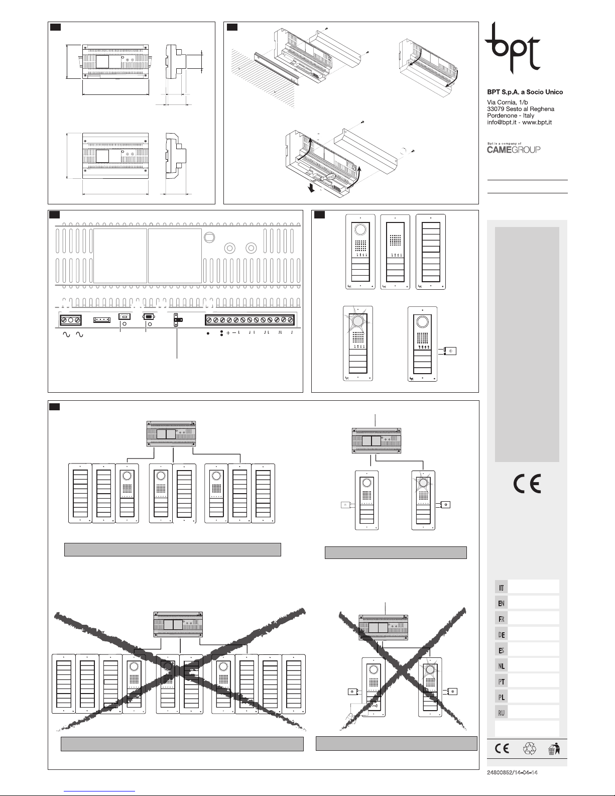
Installation B
DasNetzgerätmussIMMERwaagerechtinstalliertwerden.
DasGerätkannaufeinerDIN-Schiene(EN50022)a,auf
einementsprechendenSchaltkastenoderanderWand
mithilfevonKlemmenabdeckungeninstalliertwerden.
GehenSiefürdenAusbauvor,wieinAbbildungcgezeigt.
HINWEIS Falls das Netzgerät in einem Metallgehäuse
installiert wird, für ausreichende Belüftung sorgen.
Technische Daten
Typ VA/01
Versorgungsspannung[VAC]230
Max.Stromaufnahme[AAC]0,35
Max.Verlustleistung[W] 25
NennspannungAußenstationen[VDC] 18
StromaufnahmeAußenstationen[A] 0,6
SpitzenspannungAußenstationen[VDC] 18
SpitzenstromaufnahmederAußensta-
tionen[A] 1,1<15’’(*)
VersorgungsspannungHauptleitung
[VDC]20
StromaufnahmeHauptleitung[A] 0,8für1’
StromaufnahmeHauptleitung[A] 0,2für3’
Abmessungen[DIN] 12
Lagertemperatur[°C] -25÷+70
Betriebstemperatur[°C] 0÷+35
Schutzart[IP] 30
(*)1,6A<15’’beinichtangeschlosseneroderseparat
versorgterHauptleitung.
Funktionen C
Klemmenbretter a
~Netz
~
AusgangAux1OpenCollectormax100mA
+12V GemeinsamerKontakt
AusgangAux2OpenCollectormax100mA
+
–VersorgungAußenstationen18VDC(*)
BIN1 EingangBUS-LeitungvonderAußenstation1
BIN2 EingangBUS-LeitungvonderAußenstation2
BIN3 EingangBUS-LeitungvonderAußenstation3
BOUT AusgangTrägerleitung
(*)DasGerätistvorÜberlastungenundKurzschlüssen
elektronischgeschützt.
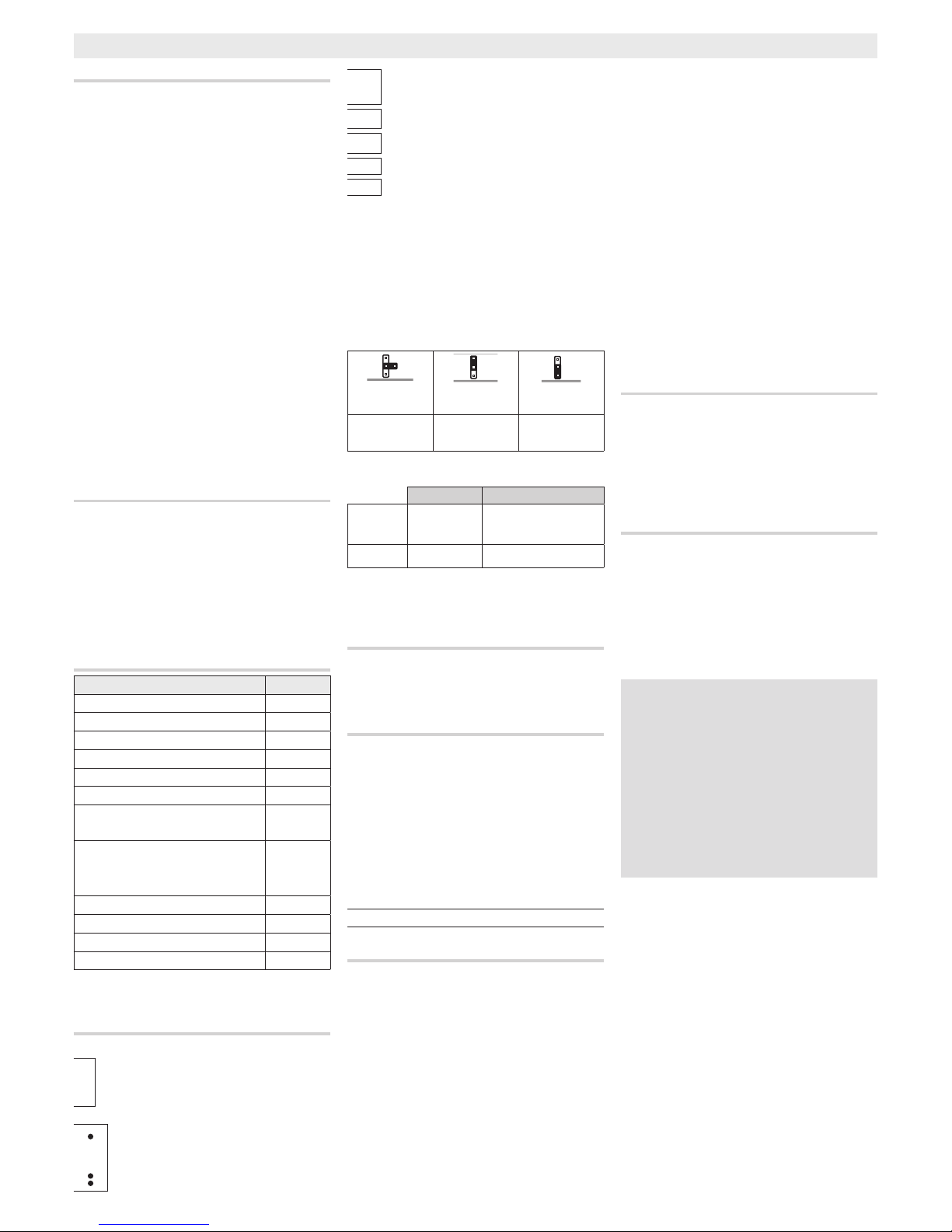
Steckverbinder
c RS232:FürzukünftigeBenutzungreserviert.
MINI USB:SteckverbinderfürdieProgrammierung
mitPC
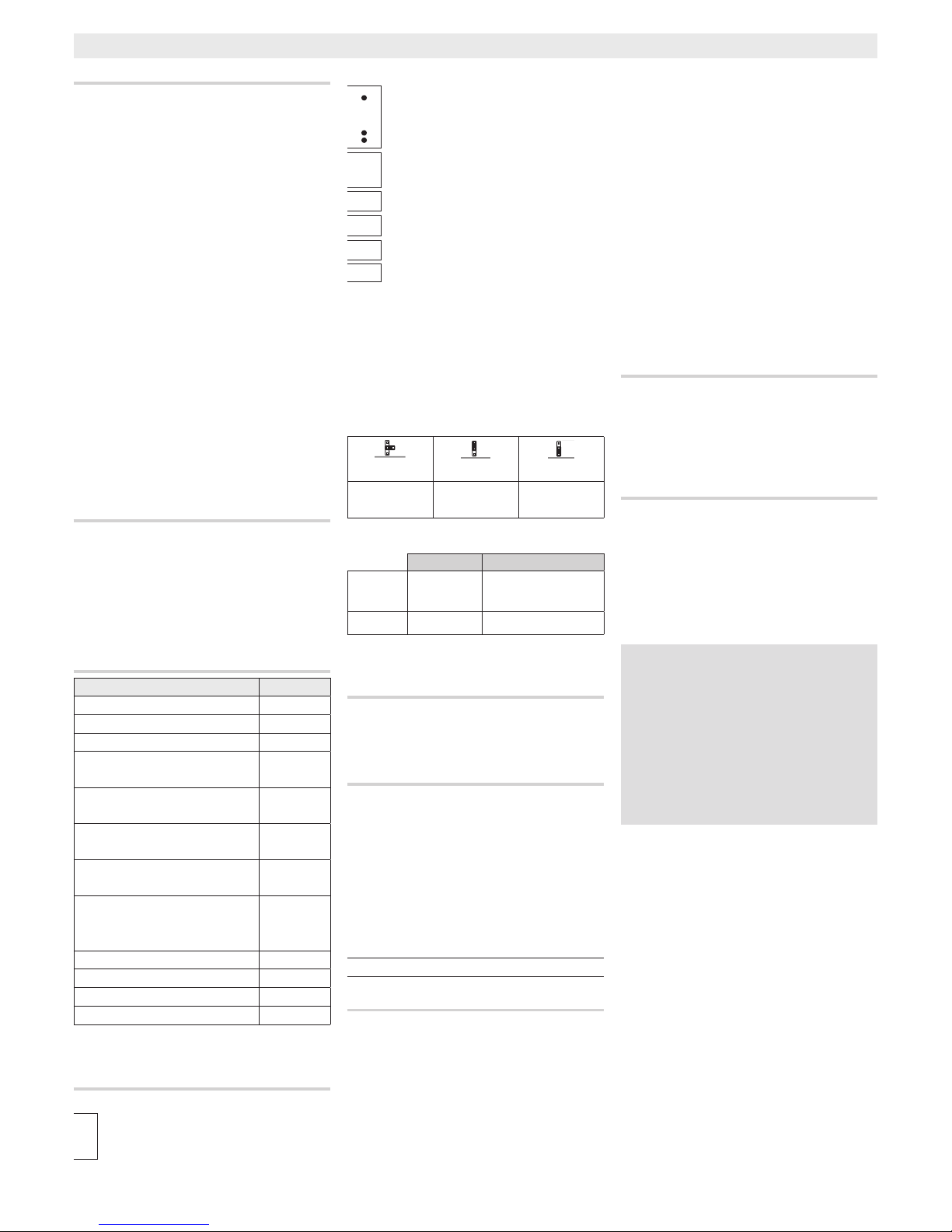
Taste PROG (**)
Jumper RFID PROG (**)
RFID
Default Codeeingabe LöschenderCo-
des
Der LED
Farbe Bedeutung
DL1
(**) Gelb Programmierungsstand
DL2 Grün USBangeschlossen
(**)Siehe“ProgrammierhandbuchderAußenstationen
DC/01-DVC/01-DC/01ME-DVC/01ME”.
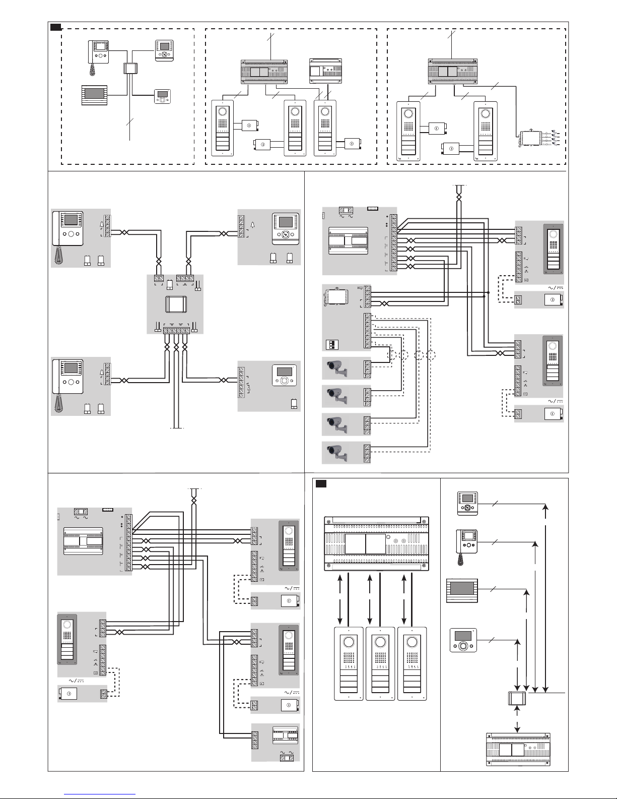
Stromaufnahmen D E
aMitAußenstationen„imRuhezustand“
BeiEingeschalteterKamera
c Bei„aktivem“Elektroschloss
Abstände G
aVCM/2D
L1,L2,L3≤100m;
L1+L2+L3≤300m.
VCM/1D
La+Le≤100m;
Lb+Le≤100m;
Lc+Le≤100m;
Ld+Le≤100m;
La+Le+L1(L2,L3)≤150m;
Lb+Le+L1(L2,L3)≤150m;
Lc+Le+L1(L2,L3)≤150m;
La+Lb+Lc+Ld+Le+L1+L2+L3
≤600m.
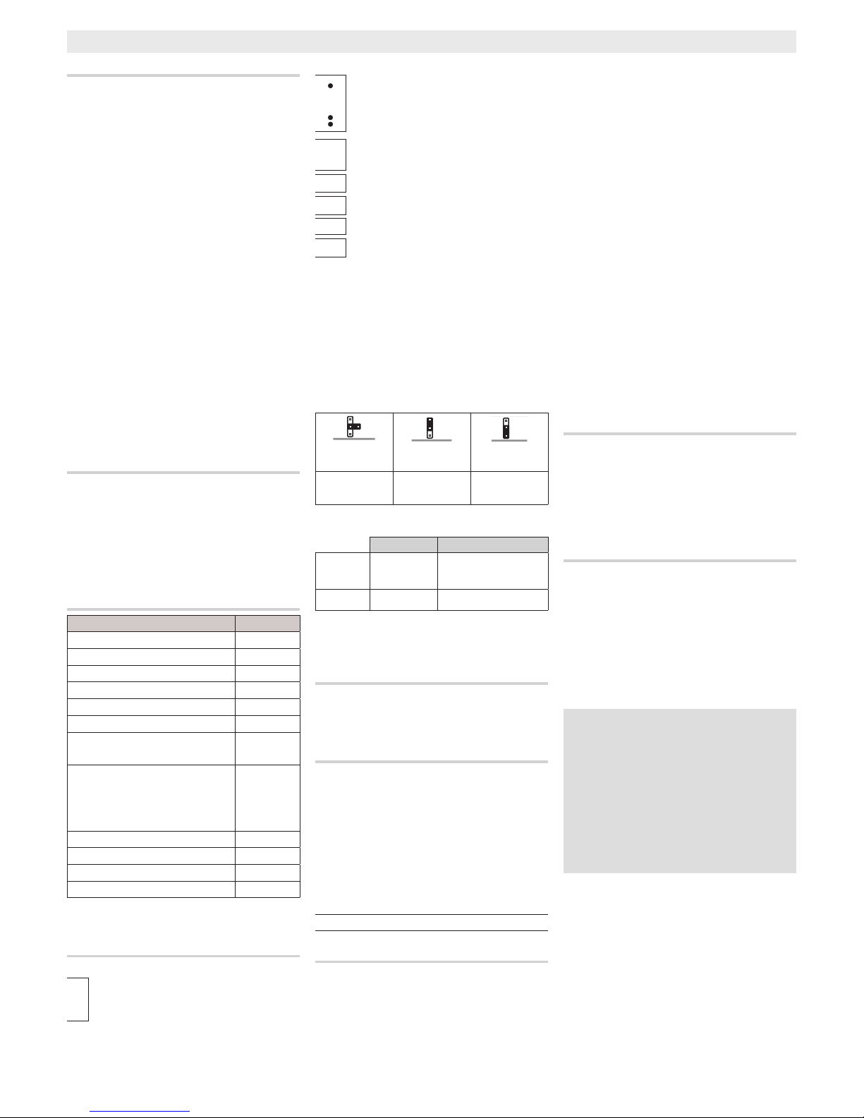
Programmierung
Einer Intercom-Gruppe H
y Die Programmierung der Intercom-Gruppe muss
ausgeführt werden,nachdemsämtlichenInnensprech-
stellen der Typ der Ruftaste oder der Anrufcode zuge-
wiesen wurde.
DrückenSiedieTastePROGdesNetzgerätesmindestens
25Sekundenlang,bisdieLEDPROGschnellblinkta,
undbringenSieanschließenddenJumperRFIDPROGindie
Position“+” .FürdieAktivierungderIntercom-Funktion
stellenSiedenJumperaufdieInnensprechstelle,dieSie
programmierenmöchten,unddrückenSiedieRuftaste,mit
derSieanrufenmöchten:EsfolgteinakustischesSignal,das
dieerfolgteProgrammierungbestätigtc.
FahrenSiefort,indemSiedieselbenSchrittefüralleanderen
Innensprechstellenwiederholen,dieindieGruppemit
Intercom-Funktionaufgenommenwerdensollen.
UmdieProgrammierungzuverlassen,drückenSiekurzdie
TastePROGdesNetzgerätes undbringenSiedenJumper
RFIDPROGindieStandardposition.
HINWEIS:FallskeineEingabeerfolgt,endetderVorgang
automatischnach30Minuten.
Immerdann,wenneineInnensprechstelledurchZuweisung
derRuftasteineineIntercom-Gruppeaufgenommenwur-
de,kannsienichtmehrausdieserGruppeausgeschlossen
werden.
UmdieRuftasteeinerInnensprechstellezuändern,die
bereitsalsIntercom-Stelleprogrammiertwurde,undneue
InnensprechstellenzurGruppehinzuzufügen,istesausrei-
chend,diegeradebeschriebeneAbfolgezuwiederholen.
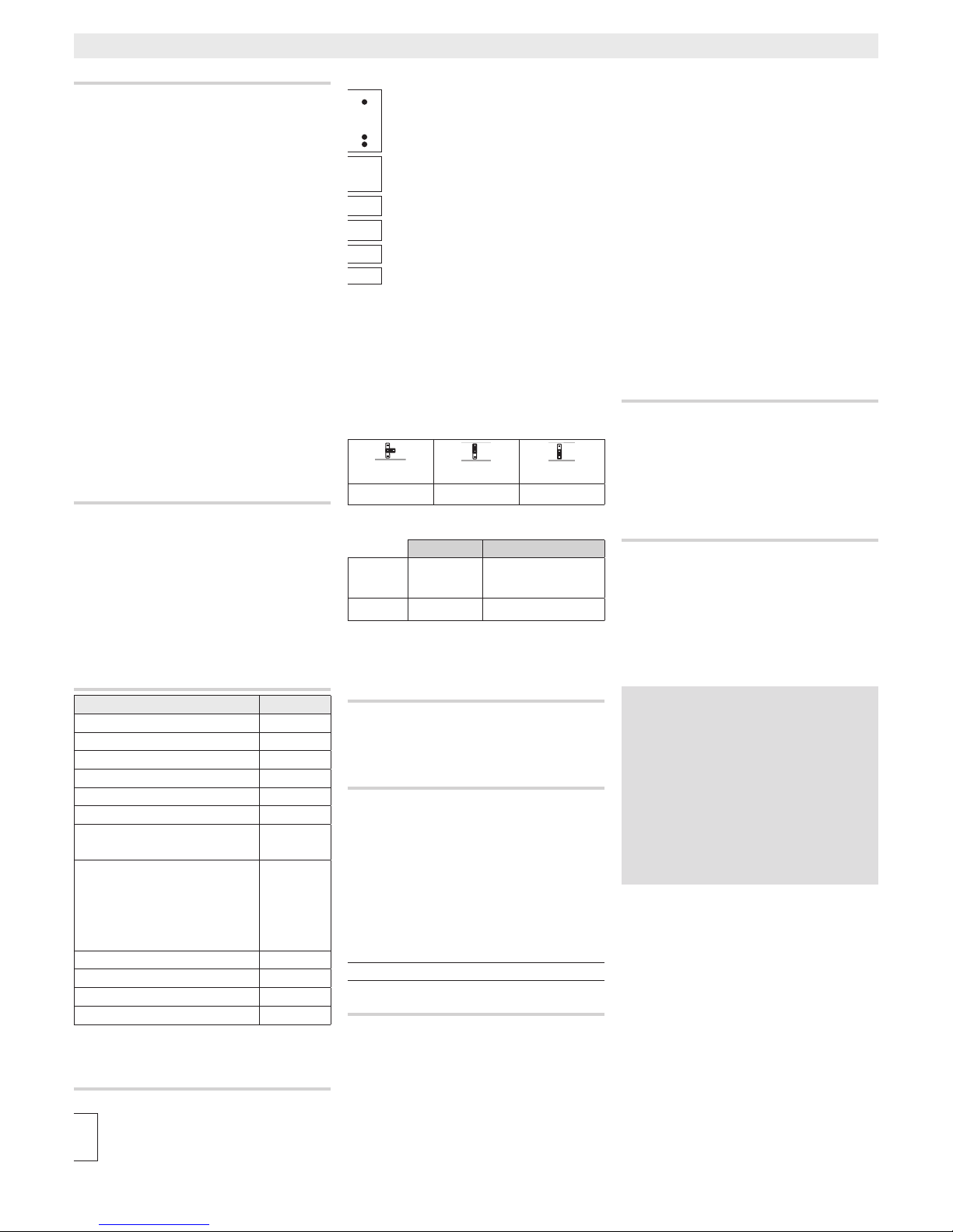
Deaktivierung der Intercom-Funktion I
DrückenSiedieTastePROGdesNetzgerätesmindestens
25Sekundenlang,bisdieLEDPROGblinkta,undbringen
SieanschließenddenJumperRFIDPROGmindestens20Se-
kundenlangindiePosition„+“.BringenSiedenJumper
RFIDPROGanschließendwiederindieStandardposition,
umdieProgrammierungzuverlassenc.
Anschlussbeispiele FL
MithilfedesNetzgerätesVA/01unddersoebenbeschrie-
benenVorgehensweiseistesmöglich,eineGruppevon
InnensprechstellenmitIntercom-Funktionzuprogram-
mieren.WennSiemehralseineIntercom-Gruppeanlegen
möchten,müssenSieGerätevomTypVSE/301verwenden.
Esistnichtmöglich,gleichzeitigeineIntercom-Gruppe
mitVA/01undandereGruppenmitVSE/301L zu
kongurieren.
ENTSORGUNG
Sicherstellen,dassdasVerpackungsmaterialnichtdie
Umweltbelastet,sonderndengeltendenVorschriften
desBestimmungslandesentsprechendentsorgtwird.
DasnichtmehrbenutzbareGerätumweltfreundlich
entsorgen.DieEntsorgungdesGerätshatgemäßden
geltendenVorschriftenzuerfolgenundesistvorzugsweise
eineWiederverwertungderBauteilevorzusehen.Die
wiederverwertbarenBauteilesindmitdembetreenden
SymbolundMaterialzeichenversehen.