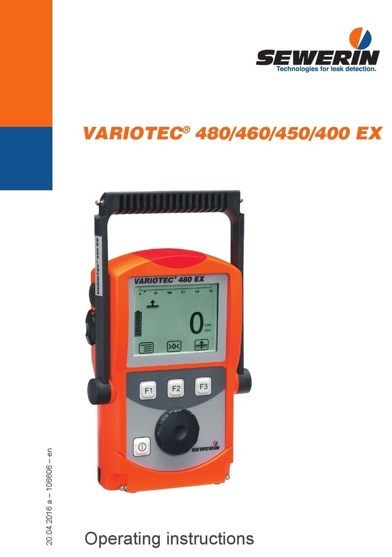
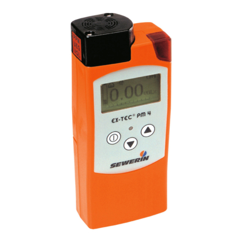
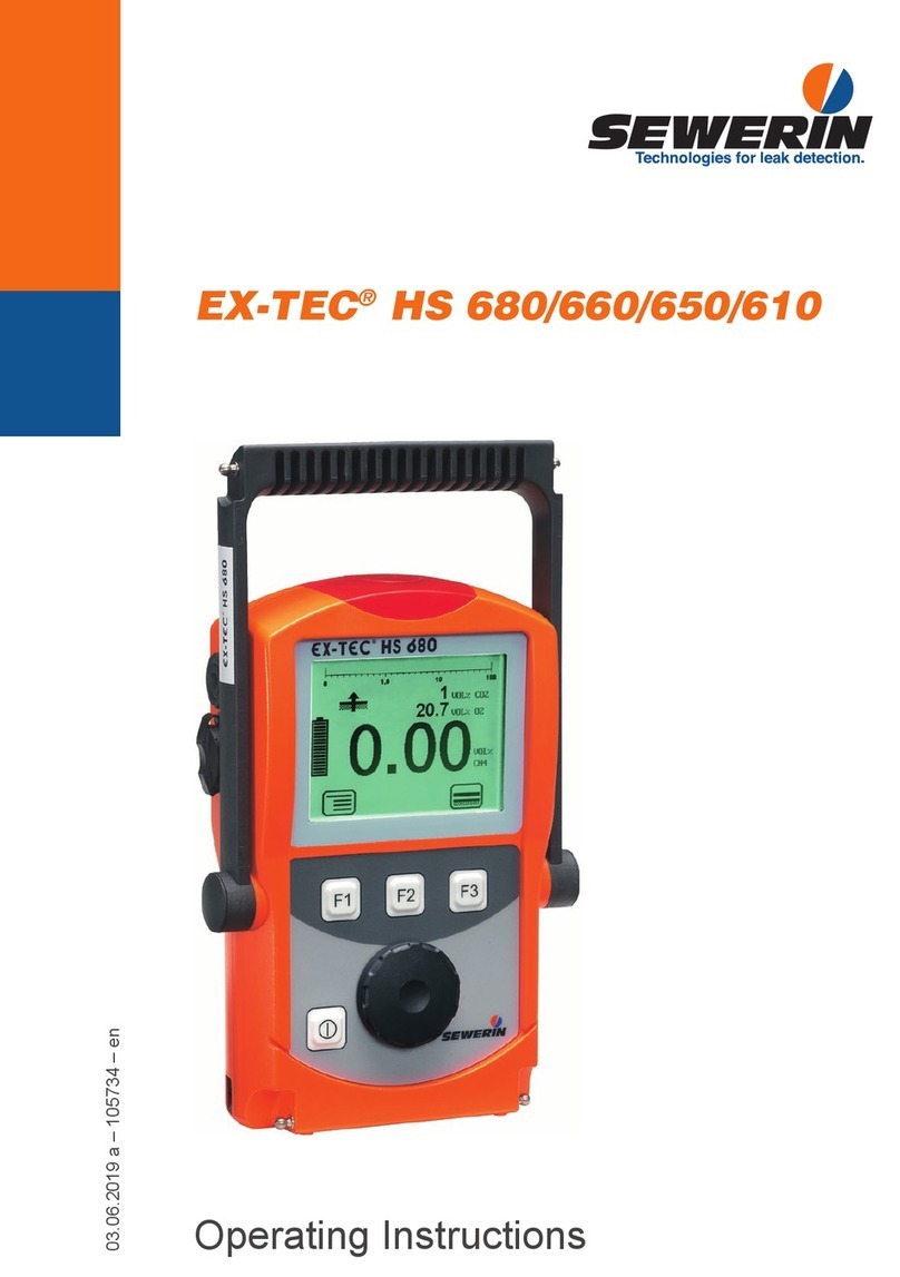
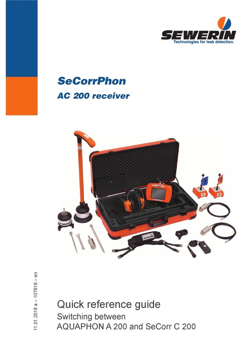
sewerin EX-TEC Combi User manual

Operating
Instructions

Measurable success by Sewerin equipment
Congratulations.
You have chosen a quality instrument manufactured by Hermann
Sewerin GmbH.
Our equipment will provide you with the highest standards of perfor-
mance, safety and efficiency. They correspond with the national and
international guide-lines.
Please read and understand the following operating instructions before
using the equipment; they will help you to use the instrument quickly and
competently. If you have any queries we are available to offer advice
and assistance at any time.
Yours
Hermann Sewerin GmbH
Robert-Bosch-Straße 3
33334 Gütersloh, Germany
Tel.: +49 5241 934-0
Fax: +49 5241 934-444
www.sewerin.com
info@sewerin.com
Sewerin Ltd.
8, Walsworth Road
Hitchin
Hertfordshire
SG4 9SP, UK
phone: +44 1462-634363
www.sewerin.co.uk
info@sewerin.co.uk
Sewerin USA, LLC
13551 W. 43rd Drive, Unit R
Golden, CO 80403-7272
phone: +1 303-424-3611
fax: +1 303-420-0033
www.sewerin.net
jerry.palmer@sewerin.net
SEWERIN Sarl
17, rue Ampère - BP 211
67727 HOERDT CEDEX, France
Tél. : +33 3 88 68 15 15
Fax : +33 3 88 68 11 77
www.sewerin.com
sewerin@sewerin.fr
SEWERIN IBERIA S.L.
c/ Cañada Real de Merinas, 17
Centro de Negocios „Eisenhower“
Edificio 5; Planta 2 - C
28042 Madrid, España
Tel.: +34 91 74807-57
Fax: +34 91 74807-58
www.sewerin.com
info@sewerin.es

Illustration EX-TEC Combi
EX-TEC® Combi
Device variation 1
Device variation 2
EX-TEC® Combi
100%

Brief operating instructions
EX-TEC Combi: brief operating instructions
Switch on/off
Toggle between GAS WARNING/GAS
MEASUREMENT operating modes
(Device variation 2)
Device variation 1: Toggle between
GAS WARNING/GAS MEASURE-
MENT operating modes
Switch pump on/off
(in GAS MEASUREMENT mode)
Toggle between automatic/manual gas
switching
Change the gas displayed (in manual
operation)
Zero-point correction for the gas dis-
played
Display gas alarm thresholds AL1 and
AL2
Acoustic clearance of the AL1 alarm
Switch LCD illumination on/off (switches
off automatically after about 4

Operating Instructions
15.06.2005 – V2.X – 103401 – en
EX-TEC® Combi

For your safety
This product may only be operated by appropriately-trained persons who
are familiar with the relevant operating manual.
It may only be used for its designated purpose, i.e. for industrial and com-
mercial use.
Repair work may only be carried out by specialists or by persons who have
undergone appropriate training.
Any alterations or modifications to the product require the prior approval of
Hermann Sewerin GmbH. In the event of unauthorised alterations to the
product the manufacturer accepts no liability for damage.
Only Hermann Sewerin GmbH accessories may be used with the product.
Only spare parts approved by us may be used for repairs.
Hermann Sewerin GmbH accepts no liability for damage resulting from
non-compliance with the foregoing. The guarantee and liability provisions
in the Hermann Sewerin GmbH terms of sale and supply are not extended
by the foregoing.
We reserve the right to make changes in the context of continued techni-
cal development.
In addition to these instructions, please comply with generally applicable
safety and accident-prevention regulations!
Symbols used:
CAUTION!
This symbol warns of dangers that may threaten
the safety of the user or maty damage or destroy
the product.
Note:
This symbol flags information and hints extending
beyond the actual operation of the product .
This symbol will hereinafter identify all operating
modes and measuring techniques not tested by
DMT!
(⊗)

I
Contents Page
1 EX-TEC Combi system ...........................................................1
1.1 Excess-gas warning and measuring instrument .......................1
1.2 Fields of application ..................................................................2
1.3 Test certificates .........................................................................4
1.4 Carrying equipment ...................................................................5
2 Safety .......................................................................................6
2.1 Safety notes ..............................................................................6
3 Measuring operation ...............................................................8
3.1 Instrument description ...............................................................8
3.2 Switching on ..............................................................................9
3.3 Modes .....................................................................................13
3.4 Switching gases ......................................................................15
3.5 Alarms .....................................................................................16
3.6 Instantaneous value alarms (AL1, AL2, AL3) ..........................17
3.7 Short-term value alarm (KZW), long-term value alarm (LZW),
minimum and maximum values (MIN/MAX) ............................23
3.8 Zero point adjustment .............................................................26
3.9 Illumination and contrast .........................................................26
3.10 Operating hours display and battery alarm .............................27
3.11 Switching off ............................................................................28
4 Charging ................................................................................29
4.1 Charging and charge maintenance .........................................29
4.2 Self-discharge .........................................................................30
5 Testing/maintenance .............................................................31
5.1 Function testing, testing display accuracy, maintenance ........32
5.2 Test set ....................................................................................34
5.3 Test gases ...............................................................................35
5.4 Testing the pump power, zero point and sensitivity .................37

II
Contents Page
6 Info menu ...............................................................................39
6.1 Menu structure ........................................................................39
6.2 Overview .................................................................................40
7 Adjustment menu ..................................................................43
7.1 Menu structure ........................................................................43
7.2 Setting the H2S sensor ............................................................44
7.3 Setting the CO sensor .............................................................45
7.4 Setting the O2 sensor ..............................................................46
7.5 Setting the CO2 sensor ............................................................47
7.6 Setting the CH4 sensor ............................................................48
7.7 Setting the measurement quantity ..........................................50
7.8 Setting the test gas concentration ...........................................51
7.9 Inspection confirmation ...........................................................54
7.10 Leaving the adjustment menu .................................................55
8 Memory menu ........................................................................56
8.1 Menu structure ........................................................................56
8.2 Clearing memory .....................................................................57
8.3 Setting the memory interval ....................................................58
8.4 Setting the memory mode .......................................................60
8.5 Setting the short-term value interval .......................................61
8.6 Leaving the memory menu ......................................................62
9 System menu .........................................................................63
9.1 Menu structure ........................................................................63
9.2 Setting the date/time ...............................................................64
9.3 Setting the inspection interval .................................................66
9.4 Setting the inspection block ....................................................69
9.5 Setting the 100 vol.% range ....................................................70
9.6 Setting the PIN code ...............................................................71
9.7 Setting the alarm thresholds ..................................................73
9.8 Checking the LCD ...................................................................77
9.9 Leaving the system menu .......................................................77

III
Contents Page
10 Application hints ...................................................................78
10.1 Application hints from report of suitability examination
PFG-No. 41300401P ...............................................................78
11 Technical aspects .................................................................80
11.1 Technical notices .....................................................................80
11.2 Technical data .........................................................................82
11.3 Error messages .......................................................................93
11.4 Error and Alarm properties ......................................................97
11.5 Wearing Parts .........................................................................98
11.6 Spare parts ..............................................................................98
11.7 EC-Sensor Disposal ................................................................98
12 Hints on Disposal ..................................................................99
13 Delivery variants and accessories ....................................100
13.1 Delivery variants ....................................................................100
13.2 Accessories ...........................................................................101
Appendix ............................................................................................108
EC-type-examination certificates .........................................................108
Declaration of Conformity .................................................................... 118
Inspection protocols ............................................................................ 119

1
1 EX-TEC Combi system
1 EX-TEC Combi system
1.1 Excess-gas warning and measuring instrument
The EX-TEC Combi is a com-
bined warning and measuring
instrument for a number of diffe-
rent gases. It consists of:
the basic instrument, incorpo-
rating a pump and a data
memory for documentation
purposes
4 sensor sockets for the mea-
surement of up to 5 different
gases
The following sensors are availa-
ble:
methane CH4 or propane C3H8
or nonane C9H20 (*)
carbon dioxide CO2
oxygen O2
hydrogen sulphide H2S
carbon monoxide CO
combined H2S/CO sensor
(*) This operating manual only describes methane mea-
surement!

2
1 EX-TEC Combi system
1.2 Fields of application
The EX-TEC Combi is suitable for use in the following fields:
WARNING mode
Workplace (atmospheric) monitoring in shafts and chambers in
these fields:
drinking-water supply (metering
and transfer shafts)
district-heating systems
telecommunications shafts
effluent-treatment systems
(sewage works, pump sumps,
digestion-tank areas, rain-
overflow basins)
traffic areas
accessible culverts
Warning of explosive*) mixtures
- due to leaking gas pipes near the shaft
- due to the proximity of oil, coal, natural-gas or LPG storage
facilities
- due to the proximity of landfill sites, marshland, chemical
works, filling stations or refineries
- due to cleaning or coating work with substances containing
solvents
- due to the prohibited introduction of combustible substances
into the canal network (e.g. petrol leaks)
*) the EC prototype test certificate DMT01ATEX G 002 includes measurement functions
of the LEL methane/propane range
Warning of an oxygen defect /oxygen excess
- due to an increase in other gas components
- due to the decomposition of organic waste in shafts (e.g. wet
leaves)

3
1 EX-TEC Combi system
- due to welding and heating processes with naked flames
- due to air depletion
Warning of toxic gases
- due to the formation of carbon dioxide by bacterial conversion
processes
- due to the formation of carbon dioxide in areas where there
is mineral water
- due to the formation of carbon dioxide in exhaled air
- due to the formation of hydrogen sulphide in effluent
- due to the formation of carbon monoxide from incomplete
combustion (e.g. poorly-adjusted gas-heating systems)
- due to the formation of carbon monoxide near highways or
car-parks
GAS-MEASURING mode *)
Determining gas concentrations
Localisation
- measuring gas concentra-
tion in probe holes
- determining which probe
hole has the maximum con-
centration
Gas injection
- monitoring filling with natural
gas and oxygen extraction
- measuring the methane and
oxygen concentration
Inertisation
- monitoring flushing with
nitrogen and natural-gas
extraction
- measuring the methane and
oxygen concentration
*) No measuring function for explosion protection in accordance with guideline 94/4/EG.

4
1 EX-TEC Combi system
1.3 Test certificates
Passive explosion protection
The EX-TEC Combi has been tested for explosion protection in
accordance with the European norm (CENELEC):
EC prototype test certificate:
PTB 96 ATEX 2166, supplements 1
and 3
Identification: II 2 G EEx ib d IIB T3
Testing institution: Physikalisch-Technische Bundesan-
stalt, Braunschweig
Active explosion protection (measuring function)
The EX-TEC Combi has also been undergone a measurement-
function test in gas-warning mode:
EG prototype test certificate:
DMT 01 ATEX G002, supplement 1
(measurement range 0 – 100 %LEL
methane/propane)
Test report: PFG n° 41300401
measurement range 0 – 25 vol.%
oxygen, measurement of oxygen
defect and excess,
measurement range 0 – 5 vol.% of
carbon dioxide,
measurement range 0 – 500 ppm of
carbon monoxide
measurement range 0 – 100 ppm of
hydrogen sulphide
Testing institution: Deutsche Montan-Technologie GmbH
(DMT), Essen
The test certificates can be found in the appendix.

5
1 EX-TEC Combi system
front view side view back view
front view side view back view
1.4 Carrying equipment
TRIANGEL carrying system
a quick and easy way of carrying the instrument, consisting of a
carrying strap and neck-pad
CROSS-STRAP carrying system
a comfortable way to carry the instrument for longer periods,
consisting of 2 carrying straps crossed at the back

6
2 Safety
2 Safety
2.1 Safety notes
CAUTION!
Always use original SEWERIN accessories with the
EX-TEC Combi.
CAUTION!
Always use a probe hose with a hydrophobic filter.
CAUTION!
Do not use other than the original SEWERIN fine
dust filters with the EX-TEC Combi. Never use ac-
tivated carbon filters, as these will collect H2S gas
particles, thus causing the warning feature to stop
working properly.
CAUTION!
Observe the permissible operating temperature of
-10 °C to +40 °C.
CAUTION!
The EX-TEC Combi may only be recharged in an
area not exposed to the danger of explosion.

7
2 Safety
CAUTION!
Use the test gases only in well-ventilated areas,
as some concentrations exceed the pertinent MAK
values.
CAUTION!
The EX-TEC Combi satisfies the limits of the EMV
regulation. When using it near mobile radio equip-
ment please also observe the instructions in their
manuals.

8
3 Measuring operation
3 Measuring operation
3.1 Instrument description
Note:
Fold out the illustration inside the front cover!
Item description function
1 alarm lamp optical warning on:
breaching alarm thresholds
display of error messages
2 LCD display of:
gas concentrations
menu items
operating conditions
error messages
3 probe connection connection for:
probe hose
test set
4 keypad instrument operation
5 attachment for carrying systems:
Triangel
cross-strap
6 outlet for the gas sample
7 buzzer acoustic warning on:
breaching alarm thresholds
display of error messages
8 interface serial RS-232-interface for con-
nection to a PC (⊗)

9
3 Measuring operation
3.2 Switching on
always switch the instrument
on in “fresh air”
press the on/off key for about
3 seconds
the optical and acoustic control
signals (items 1 and 7) operate
for about 3 seconds
the LCD illumination automati-
cally switches on for about 4
minutes
available operating hours are
displayed in the form of the
battery symbol and bars (e.g.:
5 hours = 5 bars)
the built-in pump runs at con-
stant power
the software version number
(e.g. 2.1) and instrument type
(Combi) are displayed
Note:
All the following instrument displays assume that
the EX-TEC Combi is fully equipped for the mea-
surement of 5 gases (CH4 - CO2 - O2 - H2S - CO).

10
3 Measuring operation
CH4 - methane
the measurement range for
methane is displayed:
0.00 – 4.40 %VOL
depending on your last setting
a display in the %UEG, %LEL,
%LIE, %VOL, %GAZ quanti-
ties may also be possible (cf.
section 7.6: Adjusting the CH4
sensor)
CO2 - carbon dioxide
the measurement range for
carbon dioxide is displayed:
0.00 – 5.00 %VOL
depending on your last setting
a display in the %VOL, %GAZ
quantities may be possible
(cf. section 7.7: Setting the
measurement quantity)
O2 - oxygen
the measurement range for
oxygen is displayed:
0.0 – 25.0 %VOL
depending on your last setting
a display in the %VOL, %GAZ
quantities may be possible
(cf. section 7.7: Setting the
measurement quantity)
display of the sensor lifetime
in the form of bars (cf. section
11.2: Technical data):
8 bars = 100 %

11
3 Measuring operation
H2S - hydrogen sulphide
the measurement range for
hydrogen sulphide is displayed:
0 – 100 PPM
display of the sensor lifetime
in the form of bars (cf. section
11.2: Technical data):
8 bars = 100 %
CO - carbon monoxide
the measurement range for
carbon monoxide is displayed:
0 – 500 PPM
display of the sensor lifetime
in the form of bars (cf. section
11.2: Technical data):
8 bars = 100 %
Time/date
the current time (e.g.17:49)
and date (e.g. 24.02.2000) are
displayed
properly-set values are impor-
tant for the documentation of
your readings
you can correct any variances
(cf. section 9.2: Setting the
date/time)
Table of contents
Other sewerin Measuring Instrument manuals
sewerin
sewerin Multitec 560 User manual
sewerin
sewerin SeCorr 08 User manual

sewerin
sewerin Multitec 540 User manual

sewerin
sewerin SPE 2 User manual
sewerin
sewerin SR2-EX-P User manual
sewerin
sewerin Stethophon 04 User manual
sewerin
sewerin Multitec 520 User manual
sewerin
sewerin COMBIPHON User manual

sewerin
sewerin UT 9000 User manual
sewerin
sewerin Multitec 545 User manual
