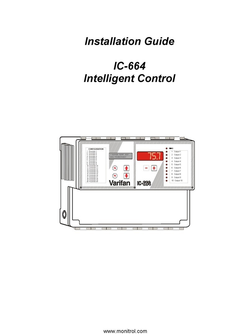
Varifan IC-68ND User manual

Installation Guide
IC-68ND
Intelligent Control
4
1
2
3
8
9
10
11
12
13
14
15
16
17
18
19
20
5
6
7
75.7
CONFIGURATION
1 Parameter 1
2 Param 2
3 Param 3
4 Param 4
5 Param 5
6 Param 6
7 Param 7
8 Param 8
9 Param 9
10 Param 10
11 Param 11
12 Param 12
13 Param 13
14 Param 14
15 Param 15
16 Param 16
17 Param 17
18 Param 18
19 Param 19
20 Param 20
ete r
ete r
ete r
ete r
ete r
ete r
ete r
ete r
ete r
ete r
ete r
ete r
ete r
ete r
ete r
ete r
ete r
ete r
ete r
1 Output 1
2 2Output
3 3Output
4 4Output
5 5Output
6 6Output
7 7Output
8 8Output
9 9Output
10 10Output
www.monitrol.com

IC-68ND INSTALLATION GUIDE
1
WARNINGS AND PRECAUTIONS
Although the manufacturer has made every effort to ensure the accuracy of the
information contained herein, this document is subject to change without notice due to
ongoing product development.
WARNINGS AND PRECAUTIONS
Defective equipment, probe failure, blown fuses and/or tripped breakers may prove
harmful to the contents of the building. Therefore it is strongly recommended to install
backup devices and alarm or warning devices. Spare equipment should also be
available at the user’s site. Equipment manufactured by the manufacturer is protected
against normal line surges. High surges caused by thunder storms or power supply
equipment may damage this equipment. For added security against line voltage surges
it is recommended that surge and noise suppression devices be installed at the
electrical distribution panel. Use of shielded cable for probes is recommended for
protection against lightning. These devices are available from most electrical supply
distributors.
RECOMMENDATIONS
The manufacturer recommends that all installation procedures described herein be
performed by a qualified electrician or installation technician. Furthermore the
manufacturer recommends to test all the functions and equipment connected to the IC,
including the alarm system and backup devices, after installation, after changes to the
installation and every month after that.
Fuse verification and replacement, as well as the proper setting of control values shall
be the responsibility of the owner of this equipment.
www.monitrol.com

IC-68ND INSTALLATION GUIDE
2
TABLE OF CONTENTS
1. Unpacking ............................................................................................................................ 3
2. Mounting Hardware Required............................................................................................. 3
3. General installation guidelines........................................................................................... 4
3.1 IC-68ND Control ............................................................................................................. 4
3.2 Electrical Cables............................................................................................................. 4
3.3 Electrical Power.............................................................................................................. 4
4. Mounting............................................................................................................................... 5
5. Control Description .............................................................................................................6
6. Connection Procedure ........................................................................................................ 8
6.1 General Wiring Diagram ................................................................................................. 8
6.2 Detailed Wiring Diagrams............................................................................................... 8
6.2.1 Typical Sensor Wiring for Probes............................................................................ 8
6.2.2 Typical Power Backup Wiring.................................................................................. 9
6.2.3 Typical Thermostat Backup Wiring........................................................................ 10
6.2.4 Communication Port Connection........................................................................... 12
7. Powering Up Procedure .................................................................................................... 12
7.1 Adjust the Line Voltage Selection Switch ..................................................................... 12
7.2 Verify all Connections................................................................................................... 12
7.3 Download the Configuration (if necessary)................................................................... 13
7.4 Hermetically Close the IC-68ND ................................................................................... 13
7.5 Troubleshooting............................................................................................................ 14
7.6 IC-68ND Compatible Probes ......................................................................................... 15
7.7 IC-68ND Compatible Modules ...................................................................................... 15
8. Specifications .................................................................................................................... 16
9. Limited Warranty ............................................................................................................... 17
TABLE OF FIGURES
FIGURE NO. 1 Mounting Position and Devices....................................................................... 5
FIGURE NO. 2 The IC-68ND Control.......................................................................................... 6
FIGURE NO. 3 IC-68ND Electronic Main Board ........................................................................ 7
FIGURE NO. 4 Typical Temperature Probe Wiring.................................................................. 8
FIGURE NO. 5 Typical Power Backup Wiring..........................................................................9
FIGURE NO. 6 Typical Thermostat Backup Wiring on ON/OFF stage................................. 10
FIGURE NO. 7 Typical Thermostat Backup Wiring on variable stage................................. 11
FIGURE NO. 8 Typical Alarm Connection Wiring.................................................................. 12
www.monitrol.com

IC-68ND INSTALLATION GUIDE
3
The purpose of this guide is to fully inform the electrician on proper wiring and installation
procedures for the IC-68ND. Full conformity of the Installation and User’s Guide will lead to a
successful installation and proper functioning of the IC-68ND control .
1. Unpacking
Unpack the IC-68ND and inspect contents for damage. Should the contents appear to be
damaged, contact your local distributor to arrange for the return of the damaged material.
The package should contain the following standard item :
• 1 IC-68ND
• 1 Temperature probe
• 1 Spare Power Fuse
• 1 Spare FAN 1 and FAN 2 fuse
• 1 Installation Guide
• 1 User’s Guide package including list of equipment, wiring diagrams, parameter list, and
detailed description of the configuration.
2. Mounting Hardware Required
This is the list of the mounting hardware needed which is not included with the product :
• Shielded two-wire cable, AWG #18 (to extend probes)
• Shielded two-wire low capacitance cable, AWG #18 to #22 (used for communication)
• 3 screws : 1 #8 X 1’’, 2 #6 X 1’’ (to hang the unit onto the wall)
• Screwdrivers
• Hammer (to punch out the knock outs)
• Soldering iron kit or approved sealed connectors
The manufacturer recommends that the following installation instructions be followed as closely
as possible and all work be performed by a certified electrician. Failure to do so may void the
warranty.
www.monitrol.com

IC-68ND INSTALLATION GUIDE
4
3. General installation guidelines
3.1 IC-68ND Control
• It is recommended to install the unit in a hallway to limit the IC-68ND’s exposure to noxious gases.
• In order to avoid condensation problems inside the controller, it is recommended to install the
IC-68ND on an inside wall. If it is not possible, use spacers to have an air gap between the
wall and the IC-68ND.
• It is required to install the IC-68ND side up with the cable entry holes facing down (see figure 1).
• The enclosure is watertight, but not splash proof or immersion proof. DO NOT WATER the
control. Cover it carefully with plastic when cleaning the room.
• The IC-68ND should be installed in easy access location but away from damaging elements
(heat, cold, water, direct sunlight, …).
• It is recommended to punch out knock outs by striking them at the bottom near the back of
the case (see figure 2).
• Do not drill the face, the side, the top or the underside of the control.
• Do not install the IC-68ND control near high voltage equipment, power supply or transformer.
3.2 Electrical Cables
• All electrical cables must be installed according to local wiring codes.
• All cable shields must be connected to the IC-68ND power ground only, except for the cable
connected to the optional PC interface (see SVPC-40 guide). The shield is needed to protect
the IC-68ND and the modules against any electromagnetic interference generated by
lightning or nearby operating machinery.
• Never use the shield as a conductor.
• Connect only one end of the shield to the ground of the IC-68ND.
• Use separate conduit for the low voltage cables (communication and probes) and the high
voltage cables. There must be at least 1 foot (30 cm) between low voltage and high voltage
conduits.
• If a low voltage cable have to cross over a high voltage cable, make this crossing at 90°.
• All cable connections must be soldered or done with approved sealed connectors.
• Probe cables must be 500 ‘ (150m) or less.
• Communication cables must be 750 ‘ (250m) or less.
• It is prohibited to use overhead cables outside the building.
3.3 Electrical Power
• Protection from electrical surge should be included in the planning of each installation.
• Every module should have a separate breaker to avoid serious consequences.
• Certain control modules (VSM-2, VSM-2/2, VPM-2, VPM-1 and CIP-1) require the same
phase and same voltage as the IC-68ND to operate.
• It is strongly recommended to have a backup power source to ensure life-sustaining
conditions in case of power failure (see figure 5).
• It is also strongly recommended to put a backup thermostat to sufficient fan and heating
system parallel to the IC-68ND module output (see figure 6).
• Backup system and alarm must be thoroughly tested and verified as working properly before
using the ventilation system.
www.monitrol.com

IC-68ND INSTALLATION GUIDE
5
4. Mounting
• Use a screwdriver to remove the 4 screws from the top of the faceplate and the 2 screws on
the access panel.
• Open both faceplates.
• Install mounting screw on wall and hang the unit in place by sliding the rear mounting hole of
the IC-68ND over the screw (see figure 1).
• Install two more screws to secure the IC-68ND in place using the bottom mounting holes.
FIGURE NO. 1 Mounting Position and Devices
REAR VIEW
TOP MOUNTING
HOLE
BOTTOM
MOUNTING HOLES
This side up
Screw Sizes:
Top mounting hole : #8 X 1”
Bottom mounting holes: #6 X 1”
www.monitrol.com

IC-68ND INSTALLATION GUIDE
6
5. Control Description
FIGURE NO. 2 The IC-68ND Control
KNOCK OUTS
provided for ease
of installation
FRONT VIEW
BOTTOM VUE
4
1
2
3
8
9
10
11
12
13
14
15
16
17
18
19
20
5
6
7
75.7
CONFIGURATION
1 Parameter 1
2 Parameter 2
3 Parameter 3
4 Parameter 4
5 Parameter 5
6 Parameter 6
7 Parameter 7
8 Parameter 8
9 Parameter 9
10 Parameter 10
11 Parameter 11
12 Parameter 12
13 Parameter 13
14 Parameter 14
15 Parameter 15
16 Parameter 16
17 Parameter 17
18 Parameter 18
19 Parameter 19
20 Parameter 20
1 Output 1
2 2Output
3 3Output
4 4Output
5 5Output
6 6Output
7 7Output
8 8Output
9 9Output
10 10Output
www.monitrol.com

IC-68ND INSTALLATION GUIDE
7
FIGURE NO. 3 IC-68ND Electronic Main Board
10A SLO-B LO
250V
10A
250V
Slo-Blo
F5
F4
F1
0.125A
250V
Slo-Blo
F3
FAST-
ACT-
ING
PRB4 PRB5 PRB6PRB3PRB2PRB1
GND
- + - + - + - + - + - +
(4-20mA)
TO POWER
SOURCE
www.monitrol.com

IC-68ND INSTALLATION GUIDE
8
6. Connection Procedure
6.1 General Wiring Diagram
Since the IC-68ND is a configurable control, the specific wiring diagram comes with the User’s
Guide particular to this installation.
6.2 Detailed Wiring Diagrams
6.2.1 Typical Sensor Wiring for Probes
The inside temperature sensor should be located in the area which gives the most accurate
temperature reading to achieve optimum ventilation. It must be located in an area protected
from operating machinery, animal or personnel manipulation or anything that could damage the
sensor. See also “3. General installation guidelines”.
If it is an outside temperature sensor, it must be installed in a location which is not influenced by
heat generated by the building or direct sunlight.
FIGURE NO. 4 Typical Temperature Probe Wiring
SHIELD
PROBE
www.monitrol.com

IC-68ND INSTALLATION GUIDE
9
6.2.2 Typical Power Backup Wiring
A backup relay (DPDT) connects to the power source 1 in normal operation but will switch to the
power source 2 if source 1 is disabled. The backup relay must be selected to ensure it is able to
support the required power load.
FIGURE NO. 5 Typical Power Backup Wiring
8 PIN RELAY DPDT
(OMRON model MK2EP-UA-AC120)
3
4
5
6
2
1
8
7
NO 2
NO 1
NC 1
NC 2
COM 2
COM 1
L2/N GND
L1
3
4
5
6
2
1
8
7
L2 L1 GND
source 1
DISTRIBUTION
PANEL
L2 L1 GND
N
LINE
115/230 VAC
source 2
DISTRIBUTION
PANEL
LINE
115/230 VAC
www.monitrol.com

IC-68ND INSTALLATION GUIDE
10
6.2.3 Typical Thermostat Backup Wiring
If the Intelligent Control or a module fails, the backup thermostats will activate the dedicated fan
or heater as soon as temperature reaches the set point of the thermostat. The thermostat must
be accessible for adjustment and must be set at 3 to 5 degrees above the fan’s relative set point
or 3 to 5 degrees under the heater relative set point.
FIGURE NO. 6 Typical Thermostat Backup Wiring on ON/OFF stage
www.monitrol.com

IC-68ND INSTALLATION GUIDE
11
FIGURE NO. 7 Typical Thermostat Backup Wiring on variable stage
www.monitrol.com

IC-68ND INSTALLATION GUIDE
12
Typical Alarm Connection Wiring
The IC-68ND provides a normally close dry contact to set off an alarm (high or low temperature,
power or control failure, …). Is strongly recommended to connect the alarm relays to an alarm
system or an auto-dialer.
FIGURE NO. 8 Typical Alarm Connection Wiring
ALARM SYSTEM /
AUTO DIALER
6.2.4 Communication Port Connection
Always connect the IC-68ND positive communication port terminal block with the module
positive communication port terminal block. Do the same with the negative communication port.
7. Powering Up Procedure
7.1 Adjust the Line Voltage Selection Switch
This switch is located on the bottom electronic board (see figure 3) and adapts the IC-68ND to
115 VAC or 230 VAC line voltage.
7.2 Verify all Connections
Once the IC-68ND is properly mounted on the wall and all modules and sensors connected to
the terminal block, perform the following steps :
1) Ensure the flat cable between the bottom electronic board and the faceplate electronic board
is properly connected.
2) Seal all cable entry holes.
Certain control modules (VSM-2, VSM-2/2, VPM-2, VPM-1 and CIP-1) require the same
phase and same voltage as the IC-68ND to operate.
Set the line voltage switch (115VAC/230VAC) inside the IC-68ND to the correct value before
powering up the Intelligent Control.
www.monitrol.com

IC-68ND INSTALLATION GUIDE
13
7.3 Download the Configuration (if necessary)
When upgrading your system with a new configuration, you will have to download the
configuration.
a) Ensure the power source of the IC-68ND is OFF (flip the circuit breaker on the distribution
panel).
b) Remove the faceplate screws and lift up the cover.
c) Insert the configuration chip (CM-8) into the socket of the main board (see figure 3). Make
sure the arrow of the configuration chip (CM-8) is pointing in the same direction as illustrated
on the main board.
d) Switch on the power source. The display on the front panel should indicate dnld for
approximately 5 seconds. If dnld is not displayed, try one more time. If dnld is still not
displayed, remove and replace the configuration chip (CM-8). Make sure the arrow of the
configuration chip (CM-8) is pointing the same direction as on the main board.
e) When the downloading procedure is complete, remove the configuration chip (CM-8) and
place it in the bottom part of the enclosure or in another safe location.
f) Cut out the faceplate labels supplied with the User’s Guide and slide them in the front panel.
7.4 Hermetically Close the IC-68ND
Close the front panel and the lower access cover and secure them with the screws previously
removed.
If the configuration chip (CM-8) is not removed after the downloading procedure, the control
will reload the factory set values each time it is reset or each time the power is turn off and
back on, erasing the values entered by the customer.
www.monitrol.com

IC-68ND INSTALLATION GUIDE
14
7.5 Troubleshooting
SYMPTOM CAUSE REMEDY
Temperature probe reads
LO
Temperature is below -6°F
(-21°C).
Probe is disconnected or
defective.
Check all connections. If the
problem persists, and the
temperature is within normal
range, replace the probe.
Temperature probe reads
HI
Temperature is above 168°F
(76°C).
Probe is short circuited or
defective.
Check all connections. If the
problem persists, and the
temperature is within normal
range, replace the probe.
Temperature average
reads Err
Temperature readings of the
probes used in the average
are too different and the
control is unable to calculate a
proper average.
Make sure all the probes are not
near a source of heat or cold and
working properly. If so, contact
your local distributor.
Displays are blank Voltage selector setting is
inaccurate.
IC-68ND is not powered.
Ten pin flat cable between the
main and the top boards of
the IC-68ND is disconnected.
Make sure the line voltage
selector switch is properly set.
Make sure the control is
powered.
Make sure the 10 pin flat cable is
connected.
Display reads 8.8.:8.8.8.
and Err continuously
Configuration memory
integrity has been
compromised.
Download the configuration once
again (see section 7.3).
Variable speed fans
hooked to a VSM or VPM
make humming noises in
auto mode, but they work
correctly in manual
mode.
Variable fans hooked to a
VSM or VPM module are not
connected on the same phase
and tension as the IC-68ND.
Make sure the IC-68ND is on the
same phase and the same
tension as the variable speed
fans that are hooked up to a VSM
or VPM module.
www.monitrol.com

IC-68ND INSTALLATION GUIDE
15
7.6 IC-68ND Compatible Probes
This is the list of all compatible probes that can be connected with IC-68ND control with a short
description of their function.
• Temperature probe 2004-1K (red cap)
Temperature probe with a temperature range of -6 to 168.7 °F (-21.1 to 76 °C).
• Temperature probe 2004-1KLT (blue cap)
Temperature probe with a temperature range of -43 to 165.7 °F (-41.7 to 74.4 °C).
• Probe averaging box PAB-4
Connection box to easily connect 4 temperature probes to obtain an average.
• Static pressure probe SPS-1
Static pressure probe with a measuring range of -0.200 to 0.200 ‘’ (-50 to 50 Pa) of water
column.
• Relative humidity probe RHP-1
Relative humidity probe with a measuring range of 10 to 90 %.
• Relative humidity probe RH-3
Universal relative humidity probe with a measuring range of 0 to 100 %.
• After market probe (Non Varifan probes)
The IC-68ND is compatible with resistive type (potentiometer, on/off switch), voltage type, 4
to 20 mA type (you have to put on jumper JP1 for PRB5 or JP2 for PRB6) and pulse type
(water and feeder counter).
7.7 IC-68ND Compatible Modules
This is the list of all compatible modules that can be connected with IC-68ND control with a short
description of their function.
ON/OFF modules
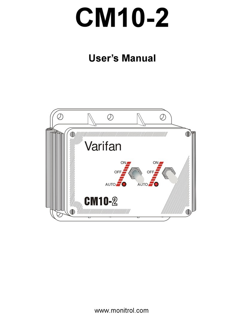
• CM10-2 (2 ON/OFF stages of 10 amperes)
• CM3-2 (2 ON/OFF stages of 4 amperes)
Variable speed module
• PM-1 (1 advanced variable stage with RPM feedback, backup probe, wind compensation…)
• VSM-2 (2 variable stages of 10 amperes with manual override)
• VSM-2/2 (1 variable stage with 2 output of 10 amperes with manual override)
• VPM-2 (2 variable stages of 10 amperes)
• VPM-1 (1 variable stage of 10 amperes)
Actuator and air inlet modules
• SVIM-1 (Advanced curtain and air inlet module working in time or potentiometer mode)
• CIP-1 (Curtain and air inlet module working in time mode)
• CIM-1 (Curtain and air inlet module working in open/close mode)
Communication modules
• SVPC-40 (PC computer interface)
• SVS-10 (Communication port multiplier)
• PMB-4 (Connection box to easily connect up to 4 PM-1 on one communication port).
Replacement Parts
www.monitrol.com

IC-68ND INSTALLATION GUIDE
16
• The 8 Relay Board uses an 1126A board
• The Typical ON/OFF Outputs Board uses an 1120A board
• The Toggles For Inlets uses an 1121A board
8. Specifications
DESCRIPTION VALUE
Input Power 12 W max
Power Source (line) 115/230 VAC, -20%, +10%
50/60 Hz
Power Fuse 0.125 A @ 250 V, Slo-Blo, 5x20mm
Relays 1 to 4
10 A @ 250 VAC
1 HP @ 250 VAC
Minimal Charge 25 mA @ 50/60Hz
FAN 1 and FAN 2 10 A @ 250 VAC, Slo-Blo
Alarm Relay 1 A @ 30 VDC
Fan1 and Fan2
Power source(LINE1 and LINE2)
230 VAC, -20%, +10%
50/60 Hz
Fan1 and Fan2 Fuse 10 A @ 250 VAC, Slo-Blo
Storage temperature -22°F à 130°F (-20°C à 55°C)
Operating temperature 32°F à 120°F (0°C à 50°C)
Temperature range -6°F à 168°F (-21°C à 76°C)
Weight 6 lb (2.72 Kg)
Dimensions 12¼”X11”X4¾” (32X28.5X11.5 cm)
www.monitrol.com

IC-68ND INSTALLATION GUIDE
17
9. Limited Warranty
The manufactured equipment and supplied components have gone through rigorous
inspection to assure optimal quality of product and reliability. Individual controls are
factory tested under load, however the possibility of equipment failure and/or
malfunction may still exist.
For service, contact your local retailer or supplier. The warranty period shall be for
two years from manufacturing date. Proof of purchase is required for warranty
validation.
In all cases, the warranty shall apply only to defects in workmanship and specifically
exclude any damage caused by over-voltage, short circuit, misuse, acts of vandalism,
lightning, fortuitous events, acts of God, flood, fire, hail or any other natural disaster.
Any unauthorized work, modification or repair on this product automatically voids the
warranty and disclaims the manufacturer from all responsibility.
The manufacturer assumes only those obligations set forth herein, excluding all other
warranties or obligations. This warranty stipulates that in all cases the manufacturer
shall be liable only for the supply of replacement parts or goods and shall not be
liable for any personal injury, damages, loss of profits, interrupted operations, fines
for infringement of the law or damages to the production of the PURCHASER and the
PURCHASER shall take up the defense and hold the manufacturer faultless
regarding any legal or extra legal proceedings, notice, or claim by the customer or by
a third party, and regarding any legal and extra legal expenses and fees brought
forward on by such damages.
MAV IC-68ND VER:1.0
October 3, 2003
www.monitrol.com
Table of contents
Other Varifan Control System manuals

Varifan
Varifan IC-610 User manual

Varifan
Varifan IC-664 User manual

Varifan
Varifan ECS 5M User manual

Varifan
Varifan CM10-2 User manual

Varifan
Varifan CPS-3M User manual

Varifan
Varifan MST-2B User manual

Varifan
Varifan MST-5C User manual

Varifan
Varifan MVS-1C User manual

Varifan
Varifan VPM-1 User manual

Varifan
Varifan ECS-2M User manual
Popular Control System manuals by other brands

Gemas
Gemas MONO Installation instructions manual

FineSPL Audio Technologies
FineSPL Audio Technologies DSC24 user manual

Reliance Foundry
Reliance Foundry R-1009-12 Installation

Siemens
Siemens SIMADYN D manual

Luda Farm
Luda Farm FarmCam Mobility installation guide

Racal Instruments
Racal Instruments 1266 manual