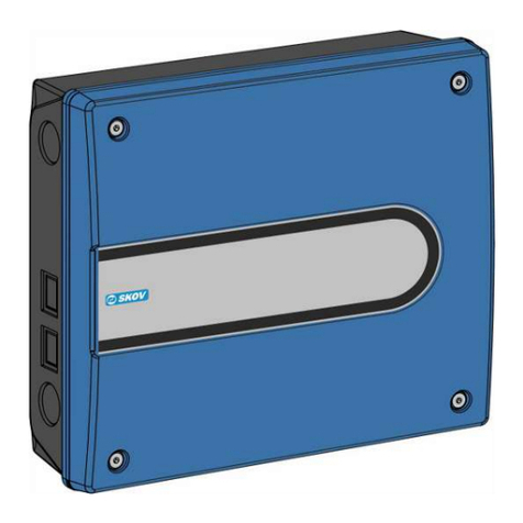
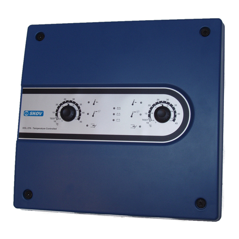
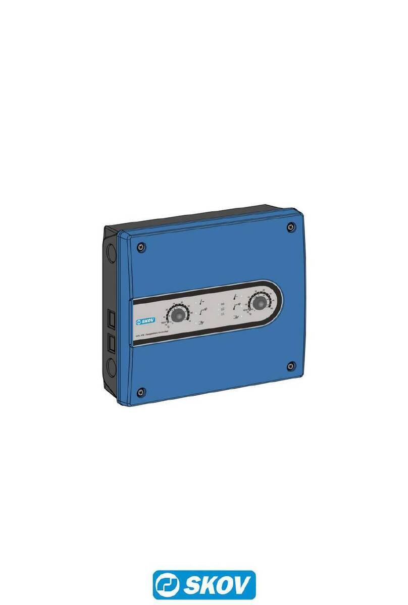
Skov DOL 278 User manual

DOL 278 ON/OFF
Emergency opening
Technical Manual
603919 • 2021-06-07
English For other language variants of this document we refer to:
Español Para otras variantes del idioma de este documento, visite:
Français Pour les versions dans d'autres langues de ce document veuillez consulter:
http://docs.skov.com/1061


DOL 278 ON/OFF
Technical Manual 3
Product and Documentation Changes
SKOV A/S reserves the right to change this document and the product herein described without further notice.
In case of doubt, please contact SKOV A/S.
The date of change appears from the front and back pages.
Note
• All rights belong to SKOV A/S. No part of this manual may be reproduced in any manner whatsoever without
the expressed written permission of SKOV A/S in each case.
• All reasonable efforts have been made to ensure the accuracy of the information contained in this manual.
Should any mistakes or imprecise information occur in spite of this, SKOV A/S would appreciate being noti-
fied thereof.
• Irrespective of the above, SKOV A/S shall not accept any liability with regard to loss or damage caused or
alleged to be caused by reliance on any information contained herein.
• Copyright by SKOV A/S.

DOL 278 ON/OFF
Technical Manual
1 Product description........................................................................................................................................5
2 Procedure........................................................................................................................................................6
3 Product survey ...............................................................................................................................................7
4 Mounting guide...............................................................................................................................................8
5 Installation guide ............................................................................................................................................9
5.1 Installation of battery................................................................................................................. 9
5.2 Installation of the TEST supply separator ............................................................................... 9
5.3 Cable dimensions for 24V DC depending on length ............................................................ 10
5.4 Setting the supply voltage on the power supply .................................................................. 10
5.5 Setup options at high power consumption ........................................................................... 11
5.6 Wiring diagrams....................................................................................................................... 12
5.6.1 Emergency opening - Medium ................................................................................................... 12
5.6.2 Emergency opening - Large....................................................................................................... 13
5.6.3 Emergency opening - Xtra Large ............................................................................................... 14
5.6.4 Emergency opening at high power consumption ....................................................................... 15
5.7 Number of fans and actuators on emergency opening........................................................ 16
6 Testing...........................................................................................................................................................17
6.1 Testing the installation............................................................................................................ 17
7 Troubleshooting guide.................................................................................................................................18
8 Technical data...............................................................................................................................................19
8.1 Dimensioned sketch ................................................................................................................ 20
DOL 278 ON/OFF
Technical Manual 5
1 Product description
DOL 278 ON/OFF is a simple emergency opening unit, which in combination with the house controller can
emergency open in case of simple types of error. In case of emergency, the system opens completely. Emer-
gency opening is not available for all types of control failures.
DOL 278 ON/OFF has a built-in 24 V DC motor power supply, battery and charger.
Available in the following variants:
• DOL 278 ON/OFF, Medium (4.2 A)
• DOL 278 ON/OFF, Large (8 A)
• DOL 278 ON/OFF, Xtra Large (10 A)
A mini UPS Mini Power unit is available as an accessory. This unit enables the house controller to regulate ven-
tilation for a short period during a power failure so that emergency control via the emergency opening unit does
not need to take over. The mini UPS module can be connected to an alarm system so that alarms will be gener-
ated when the module is active.
At high power consumption
When a high power consumption is required, the DOL 278 ON/OFF can be extended with DOL 278 ON/OFF of
4.2 A, 8 A or 10 A. See section Setup options at high power consumption [}11].

DOL 278 ON/OFF
6 Technical Manual
2 Procedure
This manual describes the mounting, installation and commissioning of a DOL 278 ON/OFF controlled emer-
gency opening system and is aimed primarily at the technicians and electricians who will be mounting, installing
and testing the emergency opening system.
The following checklist indicates the main points of the work flow regarding set up of the emergency opening
system.
Mounting
1. DOL 278 ON/OFF.
Installation
1. Battery.
2. Test supply separator.
3. Setting the supply voltage.
4. Connect cables according to the wiring diagram.
Testing
1. DOL 278 ON/OFF.
2. Battery.
Start-up

DOL 278 ON/OFF
Technical Manual 7
3 Product survey
134690 DOL 278AM EmergencyOpen. ON/OFF Medium 4.2A
ON/OFF controlled emergency opening.
Max. power consumption: 4.2 A
Battery: 4 Ah
Medium is including battery and a power supply. Medium supplies max. 4.2
A.
Supports e.g. 4 DA 175-600 and 20 DA 74 winch motors.
134691 DOL 278AL EmergencyOpen ON/OFF Large 8A
ON/OFF controlled emergency opening.
Max. power consumption: 8 A
Battery: 7 Ah
Large is including battery and two power supplies. Large supplies max. 8 A.
Supports e.g. 4 DA 175-600 and 20 DA 74 winch motors.
136700 DOL 278AXL EmergencyOpen ON/OFF XL 10A
ON/OFF controlled emergency opening.
Max. power consumption: 10 A
Battery: 14 Ah ( 2x7 Ah)
Xtra Large is including battery and three power supplies. Xtra Large sup-
plies max. 10 A.
Supports e.g. 4 DA 175-600 and 20 DA 74 winch motors.
134792 Mini-UPS, Mini-Power, Universal
Five minutes' battery backup of house controller via emergency opening
battery.
For fitting or retrofitting in an emergency opening unit.
Used in areas where 230V mains failures frequently occur.
Use one Mini UPS per house controller.
Two Mini UPS can be mounted in an emergency opening unit.

DOL 278 ON/OFF
8 Technical Manual
4 Mounting guide
1. Drill holes in the bottom of the cabinet (A).
2. Place the emergency opening unit:
- close enough to the house controller for the rubber sleeve supplied (B) to fit neatly between them (the
emergency opening unit can be placed on either side of the house controller).
- so that there is enough space, particularly above the emergency opening unit for service setting (C) of the
front panel.
3. Knock out large knock-out pieces (D) from the house controller and the emergency opening unit and mount
the rubber sleeve in one of the holes.
4. If the ventilation plug (H) is removed, move it to the left side (I) to maintain the battery ventilation.
5. Mount the emergency opening unit using Ø5 screws and, if necessary, Ø8 wall plugs (E), so that the rubber
sleeve is squeezed approx. 10 mm.
6. Mount the rubber sleeve (B) so it is waterproof.
7. Run the cables through the rubber sleeve (B).
If space is inadequate right next to the house controller, the rubber sleeve can be left out, and the cables can be
extended and routed through M25 screwed cable connections (F).
Contactor or auxiliary relay (G) must not be installed in an emergency opening unit, as the battery
may explode in the event of a fault.

DOL 278 ON/OFF
Technical Manual 9
5 Installation guide
Installation, servicing and troubleshooting of all electrical equipment must be carried out by quali-
fied personnel in compliance with the applicable national and international standard EN 60204-1
and any other EU standards that are applicable in Europe.
The installation of a power supply isolator is required for each motor and power supply to facilitate
voltage-free work on the electrical equipment. The power supply isolator is not included.
5.1 Installation of battery
Use only VRLA battery set 18 V (3 x 6 V) as the battery otherwise may explode.
Tick and attach the supplied battery date label to the outside of the cabinet. Place the battery on the shelf in the
cabinet.
Battery module 4 Ah for emergency opening unit Medium.
Battery module 7 Ah for emergency opening unit Large.
Battery modules 2 x 7Ah for emergency opening Xtra Large.
5.2 Installation of the TEST supply separator
Place the TEST supply separator next to the emergency opening unit and the house controller for weekly testing
of the emergency opening unit.
A two-pole supply separator must be used if the two-house controller is supplied from separate phases. A three-
pole supply separator must be used at several house controllers for the same emergency opening unit.
The emergency opening unit must be supplied from the same phase as the house controller.

DOL 278 ON/OFF
10 Technical Manual
5.3 Cable dimensions for 24V DC depending on length
2 A motor 4 A motor 8 A motor 10 A motor
AWG Cross
section
Length Length Length Length
16 1.5 mm20 - 41 m 0 - 20 m - -
14 2.5 mm242 – 68 m 21 – 34 m 0 – 17 m -
11 4 mm269 - 109 35 – 54 m 18 – 27 m 0 – 22 m
88 mm2110 - 217 55 – 109 m 28 – 54 m 23 – 43 m
Example Note the limited maximum distance between emergency opening/house controller and motor of
max. 22 meters by 4 mm2 cable at 10 A motor.
5.4 Setting the supply voltage on the power supply
Before you connect supply voltage, it is important to set the voltage in the power supply so that it
corresponds to the voltage level in the local house.
1. Set the voltage in the power supply.
2. Connect the supply voltage.
200-230 V Leave the plug in (factory setting)
100-115 V Move the plug to 100-115 V
Emergency opening Medium 4 A: Supply voltage must be set on one module.
Emergency opening Large 8 A: Supply voltage must be set on two modules.
Emergency opening Xtra Large 10 A: Supply voltage must be set on three modules.

DOL 278 ON/OFF
Technical Manual 11
5.5 Setup options at high power consumption
When the distance between the climate controller and wall fan or actuator is long, you can avoid long, thick low-
power cables by placing DOL 278 ON/OFF close to the power-consuming units.
An unlimited number of DOL 278 ON/OFF can be installed close to wall fans and actuators to supply 24 V DC.
DOL 278 ON/OFF at wall fan
for ON/OFF emergency opening
24V / 4A, 8A or 10A supply for actuators
If fans and actuators use DOL 278 ON/OFF, the jumper for ‘Emergency opening ON/OFF’ must be set to OFF
on the relays in the climate controller.
Use additional I/O module type 3 for additional output relays.

DOL 278 ON/OFF
12 Technical Manual
5.6 Wiring diagrams
5.6.1 Emergency opening - Medium
Emergency opening - Medium
Controller
Winch motor - chimney
Winch motor - wall

DOL 278 ON/OFF
Technical Manual 13
5.6.2 Emergency opening - Large
Emergency opening - Large
Winch motor - chimney
Winch motor - wall
House controller

DOL 278 ON/OFF
14 Technical Manual
5.6.3 Emergency opening - Xtra Large
Controller
Emergency
opening - Xtra
Large
Winch motor - chimney
Winch motor - wall

DOL 278 ON/OFF
Technical Manual 15
5.6.4 Emergency opening at high power consumption
DOL 278 ON/OFF is used as extra power supply.
No. 2
No. 1
No.
xx
Climate controller
DOL 278 ON/OFF no. 3
BF 50 LPC actuator
DA 1700 dual actuator
DOL 278 ON/OFF no. 2
Supply for
actuators
24 V DC supply cables
See table 5.3 cable dimensions
Control signal
1.5 mm2 (16AWG)
DA 600/ 820 with DA 74C winch
motor
DA 175 actuator
DOL 278 ON/OFF no. 1
Supply for actuators
Fuse
Fuse Fuse
Emergency opening
Jumper in climate controller
Analog position feedback

DOL 278 ON/OFF
16 Technical Manual
5.7 Number of fans and actuators on emergency opening
The table states the maximum number of fans and actuators that can be connected to DOL 278 ON/OFF, when
DOL 278 ON/OFF is used as additional 24 V DC power supply.
DOL 278AM emergency
opening ON/OFF
Medium,
4.2A
DOL 278AL emergency
opening ON/OFF Large,
8A
DOL 278AXL emergency
opening ON/OFF X-
Large,
10A
BF 50 LPC fan 5 10 12
BF 50 ON/OFF fan 4 8 10
DA 1700 LPC and ON/OFF
dual actuator
3* 6* 7
DA 1700 LPC and ON/OFF
winch motor
30* 60* 70
DA 600/ 820 – 74C 40 80 100
DA 75A-6 245
* DA 1700 shutter and actuators must not be controlled by signal from temperature controlled emergency open-
ing. They must always be configured as ON/OFF emergency opening.
DA 75 winch motors are special and cannot be used when placing the DOL 278 ON/OFF next to the winch mo-
tor. DA 75 must be connected and supplied via thick cables from the relays of the climate controller. This is
most efficiently done by placing the DOL 278 ON/OFF next to the climate controller.
The documentation for the individual products show the power consumption to be used when calculating the to-
tal power consumption for the emergency opening system. It is important that the maximum consumption for
DOL 278 ON/OFF is not exceeded.

DOL 278 ON/OFF
Technical Manual 17
6 Testing
6.1 Testing the installation
Test when it is not so hot that the ventilation system has already opened completely. The inlets must be closed.
Charge the battery for at least 20 minutes before the first test.
1. Connect the panel/lid and supply voltage using the common external TEST supply separator for the emer-
gency opening and house controller.
• The battery light in the front panel should be green.
2. Connect the battery wires. Red battery wires to red battery connector and black wires to black battery
connector.
• The battery light should still be green after 3 minutes.
3. Disconnect the supply voltage for the emergency opening and house controller.
• The battery light should still be green while the system opens completely.
• For two-house controllers, the system opens automatically at the same time in both houses.
• The green battery light must be on during the entire opening sequence to show that the battery is in or-
der and charged.
If the lamp emits red light:
• The battery has been discharged < 16 V.
• Or the blue 15 A battery car fuse has been blown.
If the light is not on:
• The battery wire has been forgotten.
• The battery is defective.
• The wire to the front panel has been forgotten.
4. Reconnect the supply voltage for the emergency opening and house controller.
• The system must close back to its initial position when the house controller has started again.
• The battery light should still be green.
A new fully charged battery should at least be able to open the ventilation system two consecutive times.

DOL 278 ON/OFF
18 Technical Manual
7 Troubleshooting guide
The winch motor will not run:
Is supply voltage supplied to terminals F1 and F2?
If not, check:
• external TEST supply separator
• supply voltage selector on one, two or three modules
• installation fuses
• fault current relay
• AUT-MAN switch of the winch motor
• wire connection to motor lid
Battery lamp does not emit, in spite of OK supply voltage:
Is there approx. 24V DC on terminals F5-F6?
If not, check:
• panel wire connection
• external 24 V installation on F5-F6
Battery lamp does not emit light or emits red light during interrupted power supply (battery operation):
Is there approx. 18 V DC on terminals F5-F6?
If not, check:
• battery wires
• panel wire connection
• fuses (spare fuses)
• battery voltage
Winch motor is not running when supply voltage is disconnected;
The system requires 24V DC winch motors. Furthermore, the motors must be able to open at maximum load as
low as 15 V DC, as the system works using an 18 V battery. This is normally not a problem for ordinary 24 V DC
winch motors.

DOL 278 ON/OFF
Technical Manual 19
8 Technical data
DOL 278 ON/OFF
Medium
DOL 278 ON/OFF
Large
DOL 278 ON/OFF
Xtra Large
Electrical
Rated voltage [V AC] 100 – 115 / 200 – 230 ±10 %
Operating voltage [V AC] 90 – 126,5 / 180 - 253
Frequency [Hz] 50/60
Output voltage mains opera-
tion
[V DC] 24 ± 30 %
Output voltage battery oper-
ation
[V DC] 16-20
Max. motor current [A DC] 4.2 8 10
(E.g. 2 houses with each 2.1 A on one DOL 278 ON/OFF. Simultaneous motor operation in both
houses is acceptable for max. 20 % of the time and for 10 minutes at a time).
(E.g. 1 house with 4.2 A on one DOL 278 ON/OFF. Motor operation is acceptable for max. 20 % of
the time and for 10 minutes at a time).
Battery standby charge volt-
age
[V DC] 20.3
Battery charge current max. [A DC] 1.0
Battery fuse (blue “car type”
fuse with flat type connector)
[A] 15
Battery lamp OK level [V DC] > 16
Battery module, gastight
lead, VRLA type
18 V 4 Ah
(3 x 6V 4Ah)
18 V 7Ah
(3 x 6V 7Ah)
18 V 7Ah
2 x(3 x 6V 7Ah)
Environment
Operating temperature °C (°F) -10 to +45 (+14 to +113)
Storage temperature °C (°F) -25 to +60 (-13 to +140)
Protection class IP 54 (splash-proof)
It is assumed that the base surface is flat, i.e. ≤ there is a
1.5 mm difference in height, and the front panel screw is
tightened to a minimum of 1.5 Nm. 1.5 Nm.
Immunity Electromagnetic compatibility (EMC) - Part 6-2: Generic
standards - Immunity standard for industrial environments
IEC 61000-6-2
Emission Electromagnetic compatibility (EMC) – Part 6-4: Generic
standards – Emission standard for industrial environments
IEC 61000-6-4
Shipment
Cable knockouts 20 x M25 For metrical cable glands
Dimensions (H x W x D) [mm] 381 x 400 x 151 381 x 400 x 172
Dimensions crated H x W x
D
[mm] 425 x 555 x 195
Weight [g] 7900 9000 12000
Shipping weight [g] 9500 11000 13100

DOL 278 ON/OFF
20 Technical Manual
8.1 Dimensioned sketch
Medium, Large Xtra Large
Other manuals for DOL 278
2
Table of contents
Other Skov Control System manuals

Skov
Skov DOL 535 User manual

Skov
Skov DOL 532 Tunnel User manual

Skov
Skov DOL 43X cULus User manual

Skov
Skov FarmOnline+ DataLink 131545 Manual

Skov
Skov DOL Manual

Skov
Skov DOL 78T-1 User manual

Skov
Skov BlueControl Pig User manual

Skov
Skov DOL 278 User manual

Skov
Skov DA 3800 Installation instructions manual

Skov
Skov 278A User manual