BRASSELER USA BSP MAX II User manual
PM-X00-520/PM-X00-522/PM-X00-731-IR-12.13
SURGICAL POWER & ACCESSORIES
Rx Only

3
able of Contents
ntroduction Page 4
ntended Use Page 4
Warnings Page 5
Cautions Page 6
Explanation of Symbols Page 6
Features Page 7
Charging Bay – PM-X00-731 Page 8
nstallation and Removal Page 8
4-Bay Power Unit – PM-X00-520 & PM-X00-522 Page 9
4-Bay Power Unit and Operation Page 9
Battery Pack Charging Page 10
Troubleshooting Page 11
Care and Maintenance Page 13
Cleaning Recommendations Page 14
Specifications Page 16
Repair Service Page 23
Warranty Page 24
Return Goods Policy Page 25
Product Disposal Page 26
Product Ordering nformation Page 26

44
Thank you for choosing Brasseler USA® Surgical Power & Accessories as supplier of your large bone power system.
The information and procedures described in this manual are intended to assist medical professionals in
the safe and effective use, care, cleaning, sterilization and long-term maintenance of BSPMAX™ II Large
Bone Power System.
Introduction
The BSPMAX™ II 4-Bay Power Units, PM-X00-520 and PM-X00-522 are units designed to accept up to four
modular Standard Battery Pack Charging Bays, PM-X00-731. The modular standard battery pack charging
bay is intended to charge BSPMAX™ II 9.6V Battery Pack, PM-X00-710 and 12V Battery Pack, PM-X00-715.
Intended Use

• Only trained and experienced medical professionals
should use this equipment. Failure to comply with
the BSPMAX™ II Instructions for Use may result in
patient and/or medical staff injury.
• DO NOT use if damage is apparent.
• Use of Eye protection is required while operating
equipment.
• DANGER - Explosion Hazard. DO NOT use in
atmospheres containing flammable gasses
(anesthetics, etc) with concentrations within
explosive limits. Not to be used in the OR.
• Clean 4-Bay Power Unit and Charging Bay before use.
• DO NOT modify the 4-Bay Power Unit or the
Charging Bay.
• Always use the Brasseler USA® charging bay when
charging battery packs. Failure to comply may
result in patient and/or medical staff injury.
• DO NOT operate the 4-Bay Power Unit with a
damaged power cord or plug.
• DO NOT modify the ground of the 4-Bay Power
Unit power cord.
• Install the power cord of the 4-Bay Power Unit
directly into electrical outlet.
• DO NOT disassemble or service the 4-Bay Power
Unit or Charging Bay. Return to Brasseler U.S.A.
Medical, LLC, for service or repair. Failure to comply
may result in electric shock or fire.
• Always disconnect the power cord from the 4-Bay
Power Unit before performing cleaning to reduce
the risk of electric shock.
• Install and place the 4-Bay Power Unit into service
according to the EMC information in this manual.
Portable and Mobile RF communications equipment
can affect the function of the 4-Bay Power Unit.
• Under certain classifications of risk, the World
Health Organization (WHO), or local regulatory
authorities recommend special CJD (Creutzfeldt-
Jakob Disease) inactivation processing procedures.
Consult WHO and local regulations for further
information.
55
Warnings

Explanation of Symbols
Cautions
6
• DO NOT sterilize the 4-Bay Power Unit or Charging
Bays.
• DO NOT connect 4-Bay Power Units in series.
• REMOVE battery packs from Charging Bays when
4-Bay Power Unit is off to avoid battery discharge
and/or irreparable damage to battery cells.
Catalog number.
Caution.
Date of manufacture.
Do not discard. Dispose of product or recycle in accordance
with local laws and regulations.
Do not immerse.
h
Y
N
Interference.
Manufacturer.
Serial Number.
Shoc hazard, type B.
Temperature limit.
M
f
l
7
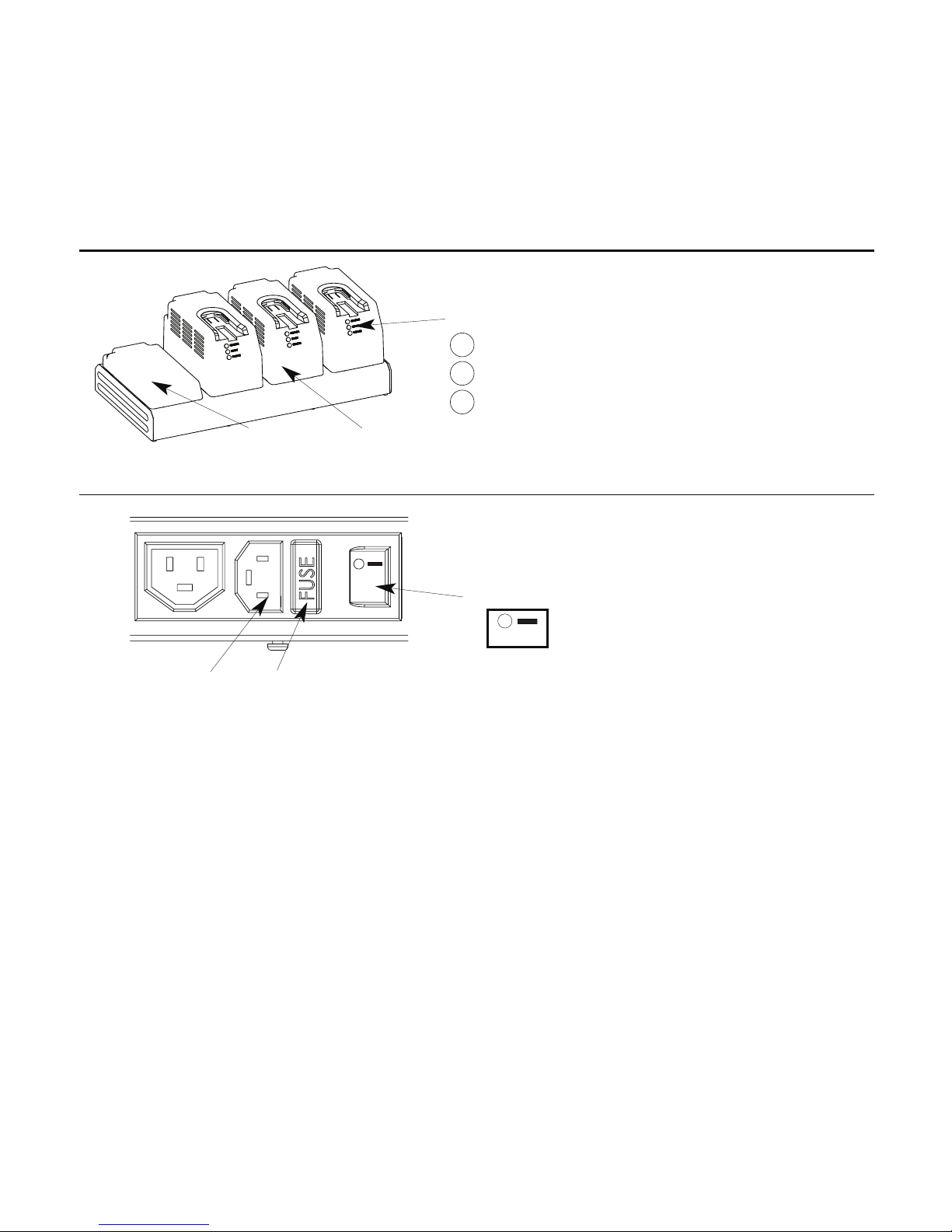
CHARGE (Yellow)
READY (Green)
SERVICE (Red)
Indicator Lights
Charging Bay
Charging Bay Cover
Power Connection
Fuse holderPower Cord Connection
Main power switch
Features
• Power Connection – Connects and disconnects Power Unit from facility power. Power connection contains:
- Fuse Holder
- Main Power Switch
- Power Cord Connection
• Charging Bay – Modular battery charging bay for BSPMAX™ II battery packs. Power Unit will accept up to
four (4) Charging Bays.
• Charging Bay Cover – Shields Power Unit’s cooling fan and Charging Bay connector when not in use. Cover
should only be removed when installing a Charging Bay.
• Indicator Lights – Provide battery status information when illuminated.
Charge - Yellow – Battery Pack is charging.
Ready - Green – Battery Pack is fully charged and ready for use.
Service - Red – Charging cycle failed.
Off/On

8
Charging Bay Installation:
• Loosen screws and remove Charging Bay Cover.
• Align front Charging Bay tab with Power Unit slot.
• Lower the Charging Bay into the corresponding side
slots and power input connection. Ensure Charging Bay
tabs are aligned with Power Unit slots.
• Apply light force to seat fully.
• Tighten screws with screwdriver.
• Verify that the Charging Bay is flush with the top
surface of the 4-Bay Power Unit and that the front
tab is engaged into power slot.
Charging Bay Removal:
• Loosen Screws.
• Remove Charging Bay.
• Install Charging Bay Cover (PM-X00-521).
The 4-Bay Power Unit can be configured with a combination of Charging Bay(s) and Bay Cover(s). The 4-Bay
Power Units (PM-X00-520 and PM-X00-522), Standard Battery Pack Charging Bay (PM-X00-731) and Charging
Bay Cover (PM-X00-521) are sold separately. The power unit charges up to four battery packs simultaneously.
Cautions:
• DO NOT over tighten screws.
• DO NOT connect power cord to the electrical connector inside the charging bay.
Tool Required:
• Standard Phillips #2 (medium size) Screwdriver.
Charging Bay – PM-X00-731
Installation & Removal
Power Input
Connection
Charging
Bay Tab
Charging Bay Cover
Charging
Bay Tab
9
The 4-Bay Power Unit can be configured with a combination of Charging Bay(s) and Bay Cover(s). The 4-Bay
Power Units (PM-X00-520 and PM-X00-522), Standard Battery Pack Charging Bay (PM-X00-731) and Charging
Bay Cover (PM-X00-521) are sold separately. The power unit charges up to four battery packs simultaneously.
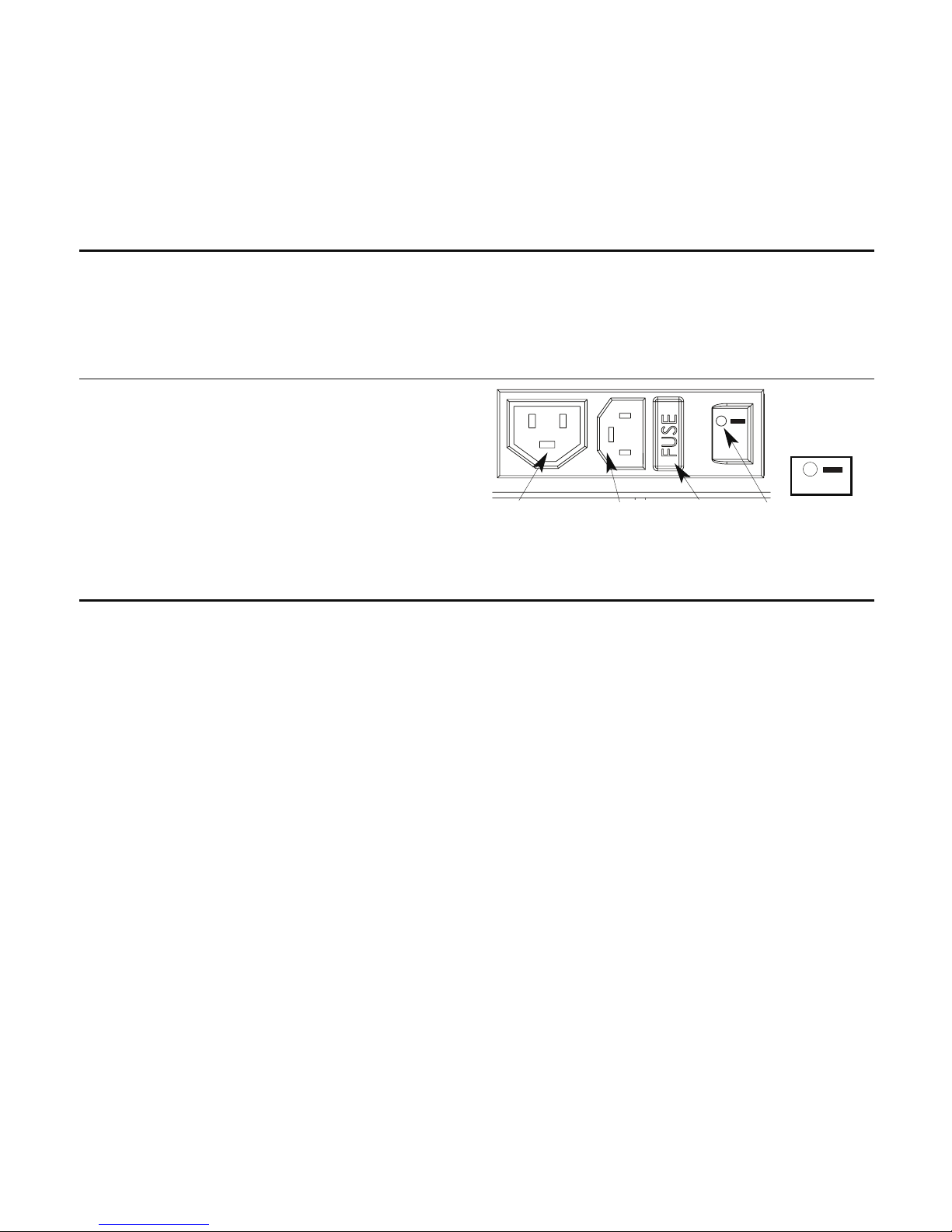
4-Bay Power nit Fuse Replacement
1. Set the main power switch to OFF (O).
2. Disconnect the power cord.
3. Squeeze and pull out the fuse holder.
4. Replace with two (2) T6.3A (250V) fuses.
5. Replace fuse holder.
6. Connect the power cord.
7. Set the main power switch to ON (-).
4-Bay Power Units – PM-X00-520 (110V) & PM-X00-522 (230V)
Power Cord
Connection
Extra female
chaining connector,
DO NOT USE
Main Power Switch
4-Bay Power Unit Operation
1. Set the main switch to the OFF position (O).
2. Connect the female end of the power cord to the power cord connection on the back of the power unit.
3. Connect the male end of the power cord to the wall outlet.
4. Activate 4-Bay Power Unit by depressing the main power switch to the ON position (-). Indicator lights will
pulse when Power unit is activated. Indicator lights will illuminate when a Batter Pack is inserted.
Fuse
holder
Off/On
10
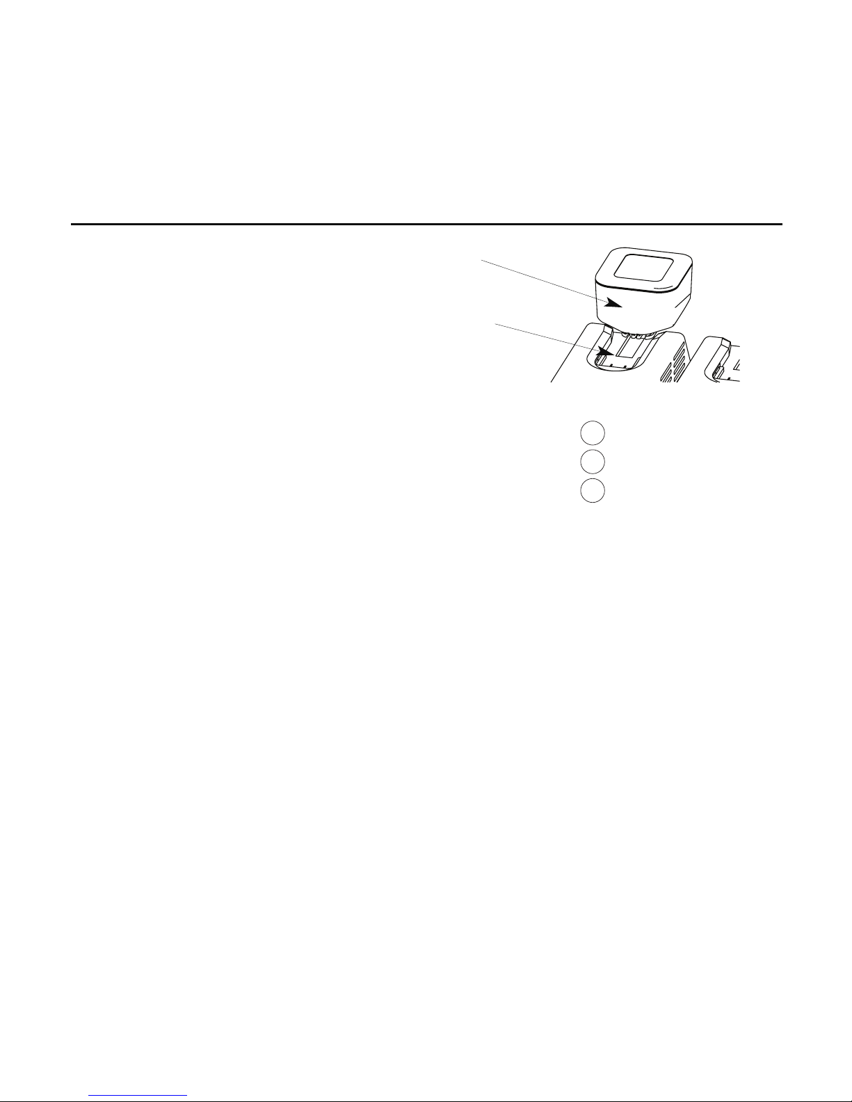
1. Insert battery pack into a charging bay receptacle.
2. Follow warnings, cautions and notes in BSPMAX™ II
PM-X00-710 (9.6V) & PM-X00-715 (12V) Battery
Packs Instructions for Use.
3. A single light will illuminate to indicate battery pack
status.
• All pulse - System is powered on.
• Yellow (pulsing) - Primary diagnostic test to determine voltage level.
• Yellow (solid) - Battery Pack is charging.
• Green (solid) - Battery Pack is charged and ready for use.
• Red (pulsing) - Secondary diagnostic test to determine charging capacity.
• Red (solid) - Charging cycle failed and battery pack should be disposed of
properly (refer to Battery IFU for Product Disposal Information).
Battery Pack Charging
Charging
Bay
Receptacle
Battery
Pac
CHARGE (Yellow)
READY (Green)
SERVICE (Red)

11
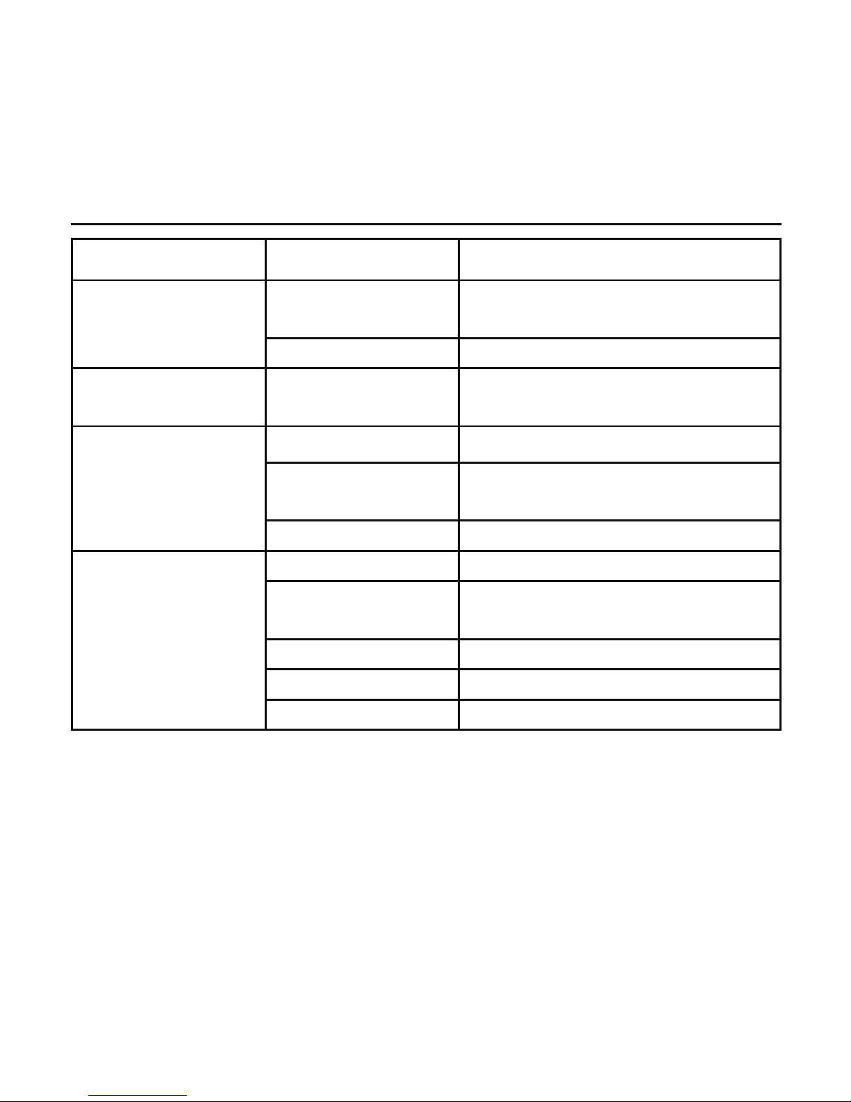
roubleshooting
Symptom Pote tial Cause Solutio
Fans and indicator lights do not function. Power cord not connected. Connect power cord.
Power unit is turned OFF (O). Turn power switch On (-).
Fuses are open/blown or missing. Replace with appropriate rated fuses.
See 4-Bay Power Unit fuse replacement.
No power at electrical outlet. Check circuit breaker.
Charging unit fan does not function. Charging bay is not installed correctly. See installation and removal.
ndicator lights do not function on
charging bays.
Charging bay is not installed correctly. See installation and removal.
Power unit fuses are open/blown. Replace with appropriate rated fuses.
See 4-Bay Power Unit fuse replacement.
Battery pack is not seated properly. Fully seat battery onto charging bay.
Charging contacts are dirty. See cleaning recommendations.
Battery pack malfunctions. Replace battery pack.
After inserting battery pack into charging
bay, red light illuminates.
Charging contacts are dirty. See cleaning recommendations.
Battery pack is at elevated temperature. Allow to cool for 20 minutes, then reinsert
into charging bay.
End of life cycle for battery pack. Replace battery pack.
Battery pack is improperly sterilized. Replace battery pack.
12
roubleshooting (continued)
Symptom Pote tial Cause Solutio
Charging bay will not fully
connect onto power unit.
Misalignment of electrical plug. Send power unit and charging bay to Brasseler U.S.A.
Medical, LLC, for service.
Electrical plug blades bent. Send charging bay to Brasseler U.S.A. Medical, LLC, for service.
ndicator lights remain illuminated
when battery pack is not installed.
Charging bay malfunctioned. Send charging bay to Brasseler U.S.A. Medical, LLC, for service.
There is a recurring power unit
open/blown fuses.
Charging board circuit failed. Send power unit to Brasseler U.S.A. Medical, LLC, for service.
Fuses have wrong rating. Replace with appropriate rated fuses.
See 4-bay power unit fuse replacement.
A power surge occurred. nstall power surge suppressor.
ndicator light does not illuminate
when battery pack is installed.
Charging bay malfunctioned. Send charging bay to Brasseler U.S.A. Medical, LLC, for service.
Fuses are open/blown or missing. Replace with appropriate rated fuses.
See 4-bay power unit fuse replacement.
Power cord not connected. Connect power cord.
Power unit is turned off (o). Turn power switch on (-).
No power at electrical outlet. Check circuit breaker.

13
Care & Maintenance
Brasseler USA® Surgical Power & Accessories
recommends that all BSPMAX™ II components
(handpieces, attachments and accessories excluding
battery packs) be returned to Brasseler U.S.A. Medical,
LLC, Service Department for routine preventive
maintenance every twelve (12) months.
Follow a regular care regimen that includes routine
cleaning and a thorough inspection for damage.
Routine preventive maintenance performed every
twelve (12) months by the Brasseler U.S.A. Medical,
LLC, Service Department can increase the reliability
and extend the life span of your BSPMAX™ II Large
Bone Power System.

14
Cleaning Recommendations
General Cleaning Precaution:
• Follow universal precautions and protective apparel
when handling and cleaning contaminated
instruments.
Warnings:
• DO NOT use if damage is apparent.
• DO NOT use 4-Bay Power Unit in the presence of
explosive gases.
• DO NOT operate the 4-Bay Power Unit with a
damaged power cord or plug.
• DO NOT disassemble or service the 4-Bay Power Unit.
Return to Brasseler U.S.A. Medical, LLC, Service
Department.
Cautions:
• DO NOT immerse the 4-Bay Power Unit or
Charging Bays in liquid.
• DO NOT use solvents, lubricants, or other
chemicals to clean the 4-Bay Power Unit or Charging
Bays unless otherwise directed.
• DO NOT allow water to collect on the 4-Bay Power
Unit or Charging Bays.
• DO NOT sterilize the 4-Bay Power Unit or Charging
Bays.
• DO NOT clean the charging contacts with
abrasives.
• Prior to changing fuses, set power unit main switch
to OFF (O), then disconnect power cord.
• DO NOT use in operating rooms or locations with
explosive gases.
• DO NOT connect 4-Bay Power Unit in series.
• Remove battery packs from charging bays when 4-
Bay Power Unit is off to avoid battery discharge
and/or irreparable damage to the battery cells.

15
Cleaning Procedures:
1. Set the main power switch to OFF(O).
2. Remove all battery packs.
3. Disconnect the 4-Bay Power Unit power cord from
the outlet.
4. Wipe the external surfaces of the 4-Bay Power Unit
and Charging Bays with a clean lint-free soft cloth
lightly dampened with a non-abrasive hospital
disinfectant.
5. Dry immediately with a clean lint-free soft cloth.
6. Clean charging contacts using a cotton swab lightly
with isopropyl alcohol. DO NOT clean the charging
contacts with abrasives.
7. Ensure equipment is completely dry before
reconnecting to power.
8. Inspect for damage or malfunctioning.
Return damaged components to Brasseler U.S.A.
Medical, LLC, Service Department.
Cleaning Recommendations (continued)

16
Specifications
PM-X00-520 PM-X00-522
nput Voltage 100VAC – 120VAC 220-240VAC
Max. Rated Current 10A 6A
Frequency 50 – 60 Hz 50 – 60 Hz
Output Voltage Max. 15VDC 15VDC
Classification Protection Class 1 Protection Class 1
Class of Rating Continuous operation Continuous operation
Socket Outlet 5A 100 – 120V ~ 50/60 Hz 3A 220 – 240V ~ 50/60 Hz
1. Performa ce
Size 17” x 8 5/8” x 6 1/4”
Weight 16.75 lb
4-Bay Power nit with 4 charging bays
Size 7 1/2” x 3 1/2” x 4”
Weight 1.8 lb
Charging Bay
Size 17” x 8 5/8” x 2 1/4”
Weight 9.55 lb
4-Bay Power nit
2. Physical Characteristics
17
Specifications (continued)
3. Complia ce Sta dards
EMC Compliance Standards: DN60601-1-2; EC60601-1; CSA 60601.1
Safety Compliance: EN60950-1; EC60950-1; CSA 60950-1; UL 60950-1
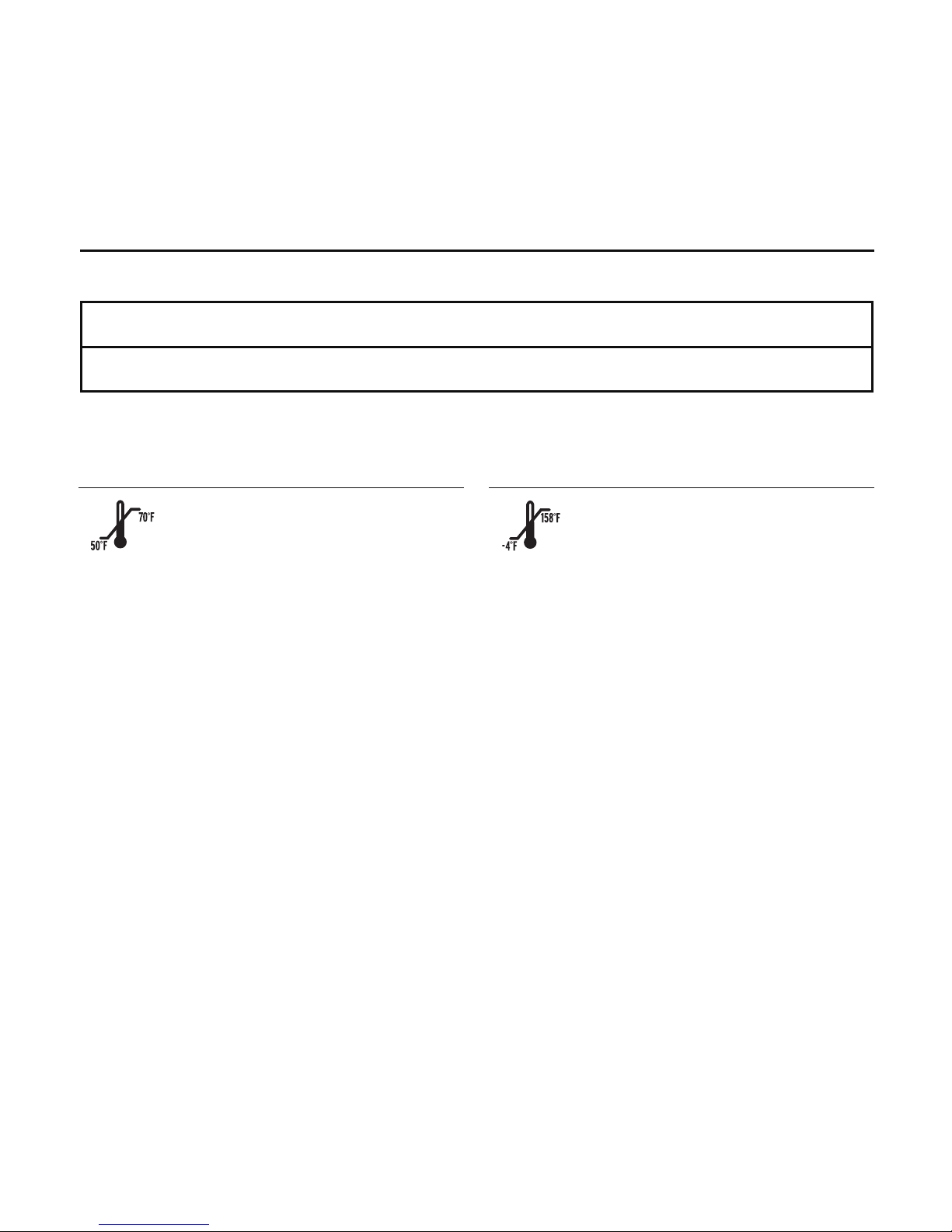
Operating:
• Ambient temperature : 50°F to 70°F (10°C to 21°C)
• Relative Humidity 30% - 75%
• Atmospheric Pressure: 700hPa to 1060hPa
ransport :
• Ambient temperature : -4°F to 158°F (-20°C to 70°C)
• Relative Humidity 10% - 100%
• Atmospheric Pressure: 500hPa to 1060hPa
4. E viro me tal Requireme ts

18
Guidance and Manufacturer’s Declaration – Electromagnetic Emissions
5. Electromag etic Compatibility Requireme ts
Specifications (continued)
The BSPMAX™ II battery charger is intended for use in the electromagnetic environment specified below.
The user of the BSPMAX™ II battery charger should assure that it is used in such an environment.
Emissio s test Complia ce Electromag etic e viro me t - guida ce
RF emissions
C SPR 11
Group 1 The BSPMAX™ battery charger uses RF energy only for its internal function.
Therefore its RF emissions are very low and are not likely to cause any interference
in nearby electronic equipment.
RF emissions
C SPR 11
Class A The BSPMAX™ battery charger is suitable for use in all establishments,
including domestic establishments and those directly connected to the public
low-voltage power supply network that supplies buildings used for domestic
purposes.
Harmonic emissions
EC 61000-3-2
Class A
Voltage fluctuations
Flicker emissions
EC 61000-3-3
Complies

19
NOTE 1: At 80MHz and 800MHz the higher frequency range applies.
NOTE 2: These guidelines may not apply in all situations. Electromagnetic propagation is affected by absorption
and reflection from structures, objects and people.
Immu ity test IEC 60601
test level
Complia ce
level
Electromag etic e viro me t - guida ce
Conducted RF
EC 61000-4-6
Radiated RF
EC 61000-4-3
3 Vrms
150 KHz to 80 MHz
3 V/m
80MHz to 2.5 GHz
3 V/m
150 MHz to 80 GHz
3 V/m
80 MHz to 2.5 GHz
Portable and mobile RF communications equipment
should be used no closer to any part of the BSPMAX™
Battery Charger, including cables, than the
recommended separation distance calculated from the
equation applicable to the frequency of the transmitter.
Recommended separation distance
d=1.67√P
d=1.67√P
80 MHz to 800 MHz
d=2.33√P
800 MHz to 2.5 GHz
Where P is the maximum output power rating of the
transmitter in watts (W) according to the transmitter
manufacturer and d is the recommended separation
distance in meters (m)
nterference may occur in the vicinity of
equipment marked with the following symbol:
Guidance and Manufacturer’s Declaration – Electromagnetic Emissions
Specifications (continued) 5. Electromag etic Compatibility Requireme ts co ti ued

20
The BSPMAX™ II Battery Charger is intended for use in the electromagnetic environment specified below.
The user of the BSPMAX™ II Battery Charger should assure that it is used in such an environment.
Immu ity test IEC 60601
test level
Complia ce
level
Electromag etic e viro me t - guida ce
Electrostatic discharge
(ESD)
EC 61000-4-2
±6 KV contact
±8 KV air
±2, 4, 6 KV contact
±2, 4, 8 KV air
Floors should be wood, concrete or ceramic tile. f floors
are covered with synthetic material, the relative humidity
should be at least 30%
Electrical fast
transient/burst
EC 61000-4-4
±2 KV for power
supply lines
±1 KV for
input/output lines
±2 KV for power
supply lines
±1 KV for
input/output lines
Main power quality should be that of a typical
commercial or hospital environment.
Surge
EC 61000-4-5
±1 KV
differential mode
±2 KV
common mode
±1 KV
differential mode
±2 KV
common mode
Main power quality should be that of a typical
commercial or hospital environment.
Guidance and Manufacturer’s Declaration – Electromagnetic Emissions
Specifications (continued) 5. Electromag etic Compatibility Requireme ts co ti ued

21
Immu ity test IEC 60601
test level
Complia ce
level
Electromag etic e viro me t - guida ce
Voltage dips, short
interruptions and
voltage variations on
power supply input
lines
EC 61000-4-11
<5%UT
(>95% dip in UT)
For 0.5 cycle
40%UT
(60% dip in UT)
For 5 cycles
70%UT
(30% dip in UT)
For 25 cycles
<5%UT
(>95% dip in UT)
For 5 sec
100% Reduction
(10 ms)
60% Reduction
(100 ms)
30% Reduction
(500 ms)
95% Reduction
(5 sec)
Power frequency
(50/60Hz)
Magnetic field
EC 61000-4-8
3 A/m 3 A/m
At 50 Hz
Power frequency magnetic fields should be at levels
characteristic of a typical location in a typical commercial
or hospital environment.
Guidance and Manufacturer’s Declaration – Electromagnetic Emissions
Specifications (continued) 5. Electromag etic Compatibility Requireme ts co ti ued
NOTE 1: UTis the alternating current mains voltage prior to application of the test level.
Other manuals for BSP MAX II
1
This manual suits for next models
3
Table of contents


