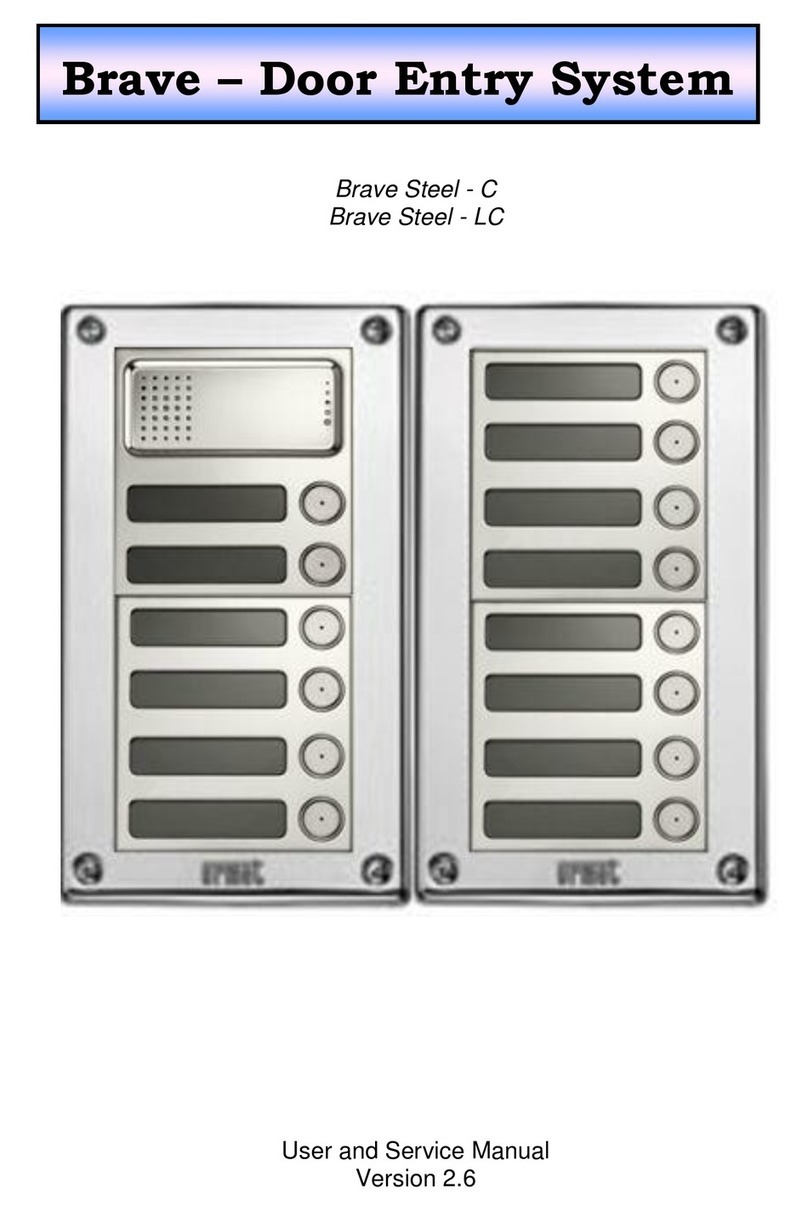
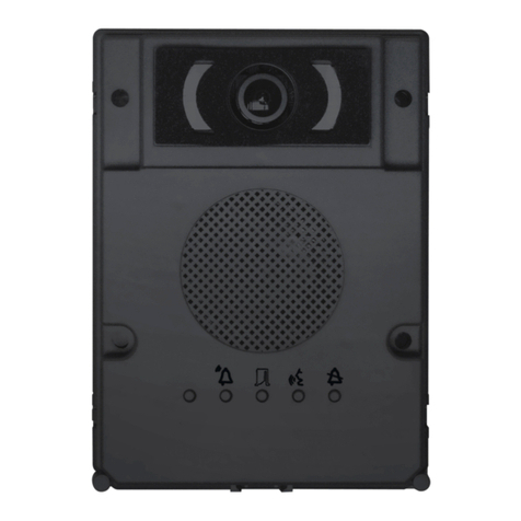
Brave Smyle - C User manual

Brave Smyle - C
Brave Smyle - LC
Brave Smyle - C/C
User guide
Version 2.6
Brave –Door Intercom


Dear customer
Congratulation to your purchase of “BRAVE SMYLE door intercom”. The
BRAVE Smyle door intercom is designed as universal project to be suitable for
different installation on the field and brings more features and possibilities.
This manual is designed for Urmet 1129 panel in 4 models with 1 or 2
buttons:
Brave Smyle - C - Comfort model
Brave Smyle - C/C - Comfort model with analog camera
Brave Smyle - LC - Low cost model
Basic features of BRAVE door intercoms
SMYLE solution –surface installation only
IP 44 casing protection
LED cards lighting
Integrated analog color camera (C/C, LC/C)
1 (2*) relay with 8 different operational modes
possibility to use electrical lock PSU for feeding the unit (C)
elektronical loudness settings ( without neccessity open the unit)
adjustable tones detection for REDIAL or Hanging Up
integrated RTC ( realtimeclock) circuit –automatical DAY/NIGHT
switching (C)
programming by phone DTMF or by USB cable from PC**
24 digits length of number including * # Flash and Pause
(C/C, LC/C) –models only
* Comfort version only
** USB cabel is an option
Version of manual V2.6 22.10.2013
Alphatech spol. s r.o.
Jeremenkova 88
140 00 Praha 4
Tel/fax: 272103334
www.alphatech.cz / info@alphatech.cz

Content
1BASIC DESCRIPTION.........................................................................................6
1.1 FEATURES........................................................................................................6
1.2 TERMINOLOGY.................................................................................................7
1.3 DIFFERENT MODELS OF SMYLE BRAVE DOOR INTERCOM ................................8
1.4 MODELS OF BRAVE DOOR INTERCOM...............................................................8
1.5 PCB SCHEMATICS............................................................................................9
2INSTALLATION.................................................................................................12
2.1 ASSEMBLY.....................................................................................................12
2.1.1 Assembly of Brave Smyle front panel........................................................12
2.1.2 Assembly of cards backlighting.................................................................13
2.1.3 Wall mounting of Brave Smyle..................................................................13
2.1.4 Replacing of cards backlighting after wall mounting...............................14
2.1.5 Cards exchange (name cards)...................................................................14
2.2 CONNECTION .................................................................................................15
2.2.1 Code relay (COSW) ..................................................................................16
2.3 CAMERA (/C VERSION ONLY) ........................................................................18
2.4 ACCSSESORIES...............................................................................................19
2.4.1 Weather hood 19
2.4.2 TimeRelay 19
2.4.3 DistyBox 19
2.4.4 Power supply 12V.....................................................................................20
2.4.5 Programming cable USB..........................................................................20
2.4.6 BlackBox 20
3DOOR INTERCOM SERVICE .........................................................................21
3.1 SIGNALLING OVERVIEW .................................................................................21
3.2 VISITOR AT THE DOOR....................................................................................22
3.3 PERSON INSIDE BUILDING...............................................................................24
3.3.1 Outgoing call 24
3.3.2 Incoming call 25
3.4 ACOUSTIC PATH SETTING...............................................................................25
4PARAMETRES PROGRAMMING ..................................................................26
4.1 PROGRAMMING BY PHONE .............................................................................26
4.1.1 Programming enter...................................................................................26
4.1.2 Parametres programming.........................................................................26
4.2 PC PROGRAMMING –BRAVESET PROGRAMM ................................................27
5DESCRIPRION OF PROGRAMMABLE PARAMETRES............................28
5.1 DIRECT NUMBERS DIAL –MEMORIES..............................................................28
5.2 RELAY(S).......................................................................................................29

BRAVE –user guide
5
5.3 BASIC PARAMETRES.......................................................................................34
5.4 TIME PARAMETRES.........................................................................................36
5.5 SYSTEM PARAMETRES....................................................................................39
5.6 HANDSFREE PARAMETRES SETTING...............................................................42
5.7 TIME PROGRAMM –AUTOMATIC DAY/NIGHT SWITCHING (C).....................45
5.8 DEFAULT SETTTING AND ERASING .................................................................47
5.9 PROGRAMMING TERMINATION .......................................................................47
5.10 PARAMETRES OVERVIEW ...............................................................................48
6TECHNICAL PARAMETRES ..........................................................................52
6.1 ELEKTRICAL PARAMETRES.............................................................................52
6.2 MECHANICAL DIMENSIONS ............................................................................52
7TABLE FOR EASY PROGRAMMING............................................................53

BRAVE –user guide
6
1 BASIC DESCRIPTION
1.1 Features
Voice communication is powered from telephone line only
Tone (DTMF) and pulse dial
Two 24digit numbers with each button (including *, #, Flash and Pause)
DAY/NIGHT switching by DTMF code or automatically by integrated
real time clocks - RTC, weekly schedule (C model)
Possibility of the call extension by * or # choice
Possibility to connect 1 or 2 (only C) independent locks for door
opening
8 different relays modes (for example: additional ring, progressive
opening)
Two codes for hanging up the unit by telephone
Two codes for door opening by telephone for 1 pulse and two codes for
2 pulses
3 x 6 codes for each relay (code by buttons at doors)
Can be connected electrically secure lock on the first switch (serial
activation code)
Possible switched on hang up by press the same push button
Possible switched on mode "Baby Call"
Possible switched on suppress receive DTMF by microphone
Possible switched on accoustic tick to the conversation for speech
recognition
Possible switched on accoustic signalization of close the relay
Adjustable number of rings before pick up an incoming call
Adjustable parameters of tone dial, length of Flash and Pause
Adjustable parametres of acoustical signalization
Adjustable parametres of tones detector
Elektronical loudness settings ( without neccessity open the unit)
Integrated analog colour camera with permanent or automatical
operation /C
Automatical camera lighting infra LED /C
Possibility of powering by external PSU 12V (Siemens) /C (C)
Easy settings of HW by DIP switch
Factory settings (default) in different levels
Programming by phone DTMF or by USB cable from PC
Integrated heating for PCB
Permanent cards lighting, switchable
Ground output for better protection against static electricity
(C) –comfort model only (Comfort)
/C - model with camera only

BRAVE –user guide
7
1.2 Terminology
Telephone line analog (2 wires) is way of connection to public network
(PSTN line) or connection to PABX –telephone exchange at
place of installation ( extension line)
Line picking up begin of call –same like OFF HOOK by handset
Line hanging up end of call –same like ON HOOK by handset
Dial DTMF - tone dial. It is dial by 2 tones combination (dial also
special character * and #. Use Flash loop interruption)
Pulse –dial by loop interruption (dial numbers only)
Incoming call connection between intercom and phone has been done by
dial from phone.The intercom picks up the call after
preprogrammed number of rings. After picking up and
password inserting you can programm the unit by phone.
Outgoing call connection between intercom and phone has been done by
dial from intercom, for example : by button pressing
Call establishing it is stage when call is picked up by called party. This stage
is not signalled at analog line. It just stop ringing tone and
call starts. It is difficult identify just this moment.
El.lock code function for relay closing by dial digits combination from
intercom buttons
Code relay between Doorphone Brave and the electric lock can be
connected code relay (COSW - CodeSwitch), which is
located at the lock and lock activates only when is the same
the specified serial combination of the Brave and set the
code on the board relay (COSW).
External code Digits combination dial from intercom buttons for relay
activation. External = dial by intercom buttons –out of
building ( at place of door intercom installation)
Internal code Digits combination dial from phone for relay activation
(DTMF). Internal = dial by phone –inside building ( phone
connected to other PBX extension)
The manufacturer continuously improves the product firmware. The
technology used allows you to upload to Brave the latest version of the
firmware any time using a standard computer with BraveSet and USB
cable. The latest version of the firmware is available at
http://www.alphatech.cz

BRAVE –user guide
8
1.3 Different Models of Smyle Brave door intercom
Brave door intercoms is designed as new generation of door intercom
units reflects all experiences collected during last 10 years of succesfull sales of
door enry solutions. Features and parametres are different for different models
of intercom to provide best balance between price and usage value.
In this manual you will meet features and parametres marked by (C) which are
specific for Brave Smyle (Comfort) model only and features and parametres
marked (M) which are planned for modular model (in Smyle solution are not
provided due mechanical solution)
Labelling of availability function :
Model LC (low cost) has all features except particularly marked
Model /C is version equiped by full colour analog camera
Model C(comfort) has special features marked by (C)
Model M(modular) has marked (M) –in mechanical Smyle solution is not
produced! And it is mentioned in programming tables only which are same for all
models.
1.4 Models of Brave door intercom
SMYLE models of Brave LC/C includes appropriate mother board with all
connectable elements.
Brave Smyle - 01C Brave Smyle - 01C/C Brave Smyle –02C Brave Smyle –2C/C
Brave Smyle - 01LC Brave Smyle –02LC
Models LCand Care different up mother board components. In model (LC)is
missing:
Second relay
RTC real time clocks for automatic DAY/NIGHT switching
Models with camera /C have added:
Possibility of external powering (usable for relay modes 7 and 8)
automatical / permanent lighting for camera (infra)
switch off cards lighting
disconnectable internal impedance for camera cable ending 75ohm

BRAVE –user guide
9
1.5 PCB Schematics
All functional and connectional elements are marked by red rounded
number at bellow picture. Explanation follow on next page.
Pict. 1 Brave Smyle mother board
(1) + (3) + (7) + (11) - version /C only
relay 2version (C) only

BRAVE –user guide
10
1. Camera lighting - infra LED. It lights up space before camera when is active.
It is possible switch off (via. item 7) –version for camera only /C
2. Connector to PC connection via USB cable
3. Analog colour camera –version with camera /C only
4. Speaker connection
5. Microphone connection (caution on polarity)
6. DIP switch in all models:
1 = Service, usage –when programming
password is forgotton. Incoming call is
going directly to programming mode
where you can set new password.
2 = Heating –switch ON integrated heating of mother board to increase resistance
against condensation water during changes of temperature
7. DIP switch position in versions (C)and /C:
3 = external power supply
4 = external power supply –switching 3 and 4 simultaneously. The powering is
used from screw 12V (11) due following reasons:
- using relay mode 7 or 8 –tpermanent switching ON/OFF is possible only
with external power supply. Dont forget setup parametr 64.
- Connection of door intercom to certain type of PBX which has problems
with current consumption on its extensions during start (Siemens).
5 = Camera lighting up (switch ON/OFF lighting of space before camera via infra
LED)
6 = Cards lighting (switch ON/OFF Leds backlighting for cards beside button)
7 = Activate permanent camera operation. In default camera is active only when
door intercom is active.
8 = Allows connect 75ohm to camera output - impedance
8. Analog telephone line (not depends on polarity)
9. Grounding –connection to ground of static electricity protection –protects
electronic of door intercom as same as PBX
10. Relays are galvanically isolated - max. 48V, max. 1,5A
model (C)has 2 relays
model (LC)has 1 relay only
on switch 1 is available relay function code (COSW - CodeSwitch) (see
page16)
11. Camera output - PAL video 1V / 75ohm. For distance longer than 25m we
recommend coax cable. For other installation UTP cable is also available. /C
model only
12. 12V power supply: - relays control
- mother board heating
- cards backlighting
- camera powering and infra LED camera lighting up
- external powering of unit (DIP 3 and 4)
The power supply might be AC as same as DC, not depends on polarity,
max consumption 250mA from 12V.
The power supply might be used also for electrical lock powering. Then we
recommend power supply 12V/1A.

BRAVE –user guide
11
You can also use 24V DC power supply. It is useful mainly at installations
where power supply is already installed and it is used for sliding doors,
RFID, etc.. The heating has control element to restrict power.
The remaining components are designed for voltage up 24V DC!!!
It not depends on polarity.

BRAVE –user guide
12
2 Installation
2.1 Assembly
2.1.1 Assembly of Brave Smyle front panel

BRAVE –user guide
13
2.1.2 Assembly of cards backlighting
2.1.3 Wall mounting of Brave Smyle
Make the mounting by attached pack with screws and plug (drill 5mm).

BRAVE –user guide
14
2.1.4 Replacing of cards backlighting after wall mounting
2.1.5 Cards exchange (name cards)
Every button has own card ( label) holded by plastic flag ( via picture).
You can print out paper labels from special Excel file (downloadable on
www.alphatech.cz or ).

BRAVE –user guide
15
2.2 Connection
The basic functionality of intercom (voice communication) needs
connection of telephone line only - LINE (8) on .Pict. 1 Brave Smyle. The line
is connected by 2 wires (a,b) and in stand by has usually voltage 24V - 60V,
short circuit current 20mA - 60mA. When line is OFF HOOK the line voltage is
7V - 10V.
Line connection Brave Smyle intercom announce by sound signal
(Reset) ♫ (capture 3.1 page.21) when is disconnected from line certain time.
Brave Smyle is analog intercom designed for connection to analog line( PSTN
line or PBX analog extension) it means line where works ordinary analog phone.
It works regardless to line polarity and in range mentioned in technical
parametres (capture 6).
Paralel connection –we not recommend! Paralell connection with
other analog phone or other door intercom is not recommended! We also not
recommend use special devices switching the line ( inteligent couplers,
adapters, etc..).
When model of Brave Smyle is with camera /C then on screw CAM
(11) on Pict. 1. connect cable for video transmission. Up to 25m you can use
one free pair of UTP cable. For longer distances you have to use coax cable
Pict. 1. Camera mode you setup by DIP switch (capture 1.5) and camera is
either activated automatically (when intercom is active) or is permanently ON
(DIP 7). Camera lighting up by infra LED is either active with camera (DIP 5) or
you can permanently switch OFF. Due DIP 8 you can paralelly connect to video
output impedance 75ohm
12V power supply (12) on Pict. 1 must be connected for mother board
heating, cards backlighting, camera powering inludes infra LEDs and for relays
control. The power supply might be AC and also DC, not depends on polarity.
From 12V is max consumption 250mA. Power supply might be used also for
electrical lock powering. Then we recommend power supply 12V/1A. You can
also use 24V DC power supply. It is useful mainly at installations where power
supply is already installed and it is used for sliding doors, RFID, etc..
You can use only 24DC power supply not AC!!! Not depends on polarity.
Relays (10) on Pict. 1 have many possibilities in practise usage. The
examples (drawings) are mentioned on Pict. 2. 12V power supply must be
connected for correct operation. The intercom unit has galvanically isolated all
important parts. Telephone line is isolated from power supply and relays
contacts are also galvanically isolated from other intercom electronic parts.
In any case must not be activated directly main voltage 120V or
230V !!! When you need control main devices please use contactors ( power
relays) as it is on Pict. 2 example (6) .

BRAVE –user guide
16
Relays connection examples are mentiond on following page. It is not all of
them but give you an idea how should be connected individual circuits (red rings
with numbers = example numbers).
1. Basic connection - 2 elektrical locks and possibility independently control
two doors. (relay mode 1 and 2 m=1) or progressive door opening (relay
mode 2 m=5 - version (C) only.
2. Two power supply –possibility to use independently two power supply One
for Brave Smyle and second for electrical locks. Second electrical lock is
connected inversaly (fire emergency exit).
3. Combination of doors with electrical lock and sliding gate at fencing.
4. Extending of previous example (3) about second doors with progressive
opening (this feature is setup in TimeRelay - optional modul)
5. Combination of electrical lock and additional ring. Relay of additional ring
might be in mode m=4 (from each button is activated for preprogrammed
time) or in mode m=6 (it is activated from one presetup button for
preprogrammed time)
6. Lighting activation m=3 (for example: way to building ) and control of for
example: heating up DAY/NIGHT mode m=8 ( (C) version only - RTC
circuit). External power supply required (DIP 3 and 4) /C version only.
Further is neccessary use contactor (Brave Smyle must not activate
230V!).
2.2.1 Code relay (COSW)
For the first switch is available function code relay (COSW CodeSwitch).
It serves primarily to secure transmission of information by switching the electric
lock. When using this function is not possible connecting or disconnecting the
voltage at the terminals to lock this lock activated. Activation is performed only
when positive result compared serial information transmitted between Brave
and the board code relay
Brave is set in several
codes to activate the relay code.
Relay can be activated codes
for one or two impulses can
differentiate activated from the
phone (DTMF) or from keys
(keyboard). The last option is
the activation code in another
mode switch than the lock.
The code information is 8 bits, but the code is 4 bits with security 4 bits which is
total of 8 bits. Practically, this is performed so that after activation the switch is
first transmits the serial code, and if they agree, so code relay connects the
electric lock.
The code relays can be connected in parallel to increase the number of
switches, but can never combine connections electric lock and the code
relay parallel!

BRAVE –user guide
17
Pict. 2 Examples of relay connection

BRAVE –user guide
18
2.3 Camera ( /C version only)
Technical parametres:
- videonorm: PAL-CCIR
- sensor: CMOS 1/3''
- picture area: 5,78x4,19mm
- resolution: 628x582pixel 380 rows
- video output: 1V p-p/75 ohm
- automatic profit control: 18dB
- minimal lighting: 3LUX
- automatic lens shutter: 1/60-1/15000sekund
- camera view: 50st.
- zoom: manually

BRAVE –user guide
19
2.4 Accssesories
2.4.1 Weather hood
It increases intercom protection
during raining. It is fixed by
adhesive labels from sides.
2.4.2 TimeRelay
Time relay allows expansion of relays
functionality. It is individual product and
detail manual you find on our websites
www.alphatech.cz
2.4.3 DistyBox
This optional modul is plastic box allows
you to connect analog unit (phone,
intercom) into wireless system DECT –
GAP (for example Siemens line GigaSet,
TopCom line Butler etc.). DistyBox is
suitable for intercom connection when are
cables not available. You just registrate
intercom as handset to DECT base
station. All features of intercom are kept.
Important: DECT base station must support
DTMF transmission between each handsets
(relay activation feature).

BRAVE –user guide
20
2.4.4 Power supply 12V
As standard we provide for Brave Smyle
intercom AC power supply 12V/1A . It is
not part of unit packaging. It must be
ordered individualy. More info about
electrical locks and power supply on
www.alphatech.cz.
2.4.5 Programming cable USB
USB cable is not part of packaging. It
must be ordered individualy. USB drivers are
downloadable on www.alphatech.cz
2.4.6 BlackBox
BlackBox is DTMF modem useful for remote programming from PC. Via
BraveSet programm you can remotely setup
all parametres of Brave Smyle intercom.
3
This manual suits for next models
2
Table of contents
Other Brave Intercom System manuals
