Bridge City HP-14 User manual


English Version
1

HP-14 Scraper Plane
Congratulations on your purchase of the HP-14 Scraper Plane. Please review the following
information for details on general set-up, usage, and maintenance prior to using your new plane.
Overview
The HP-14 Scraper Plane is a specialized hand planing tool that is great for trimming and
smoothing surfaces with difficult grain patterns.
With proper use of the HP-14 Scraper Plane, you can achieve a smoother surface and be able to
work with more delicate materials The reason for this is because the iron is scraping as opposed
to shearing, which removes very little amounts of material at a time, resulting in smooth finishes
without grain tear out.
As shown in Fig.1, the HP-14 Scraper Plane consists of the Iron, the Plane Sole, the Iron Clamping
Mechanism, the Iron Angle Adjustment Mechanism and the Front and Rear Totes.
The main parts of the plane such as the plane sole and rear tote are CNC machined stainless steel.
The rear tote has been designed with ergonomics in mind, while looking elegant with its polished
finish. The Iron Clamping Mechanism, Angle Adjustment Mechanism, and the Side Plates are CNC
machined aluminum alloy. The aluminum components are anodized to provide reduced friction,
increased hardness, while looking exquisite.
The HP-14 Scraper Plane is a hand tool that will bring you immense pleasure and comfort on
projects to come.
Fig. 1 Nomenclature
Iron An
g
le Ad
j
ustment Mechanism
Iron Clam
p
in
g
Mechanism
Front Tote
Plane Sole
Rear Tote
Side Plate
2

Mechanisms Introduction
Iron Clamping Mechanism:
The Iron Clamping Mechanism consists of the following components: the Iron Cap Knob,Iron
Cap, and the Frog. If the iron requires adjustments, simply rotate the Iron Cap Knob to firmly
press the iron against the Frog.
Fig. 2 Iron Clamping Mechanism
Iron Angle Adjustment Mechanism:
The Angle Adjustment Mechanism consists of the following components: the Anchor,Lock
Wheel, and the Lead Screw. Rotating the Lock Wheel will adjust the Iron Clamping Mechanism,
which allows you to set the angle of the iron.
Fig. 3 Iron Angle Adjustment Mechanism
图 7:刨刀调节机构
Frog
Iron Ca
p
Knob
Iron Ca
p
Iron
Anchor
Lead Screw
Lock Wheel
Frog Axle
3

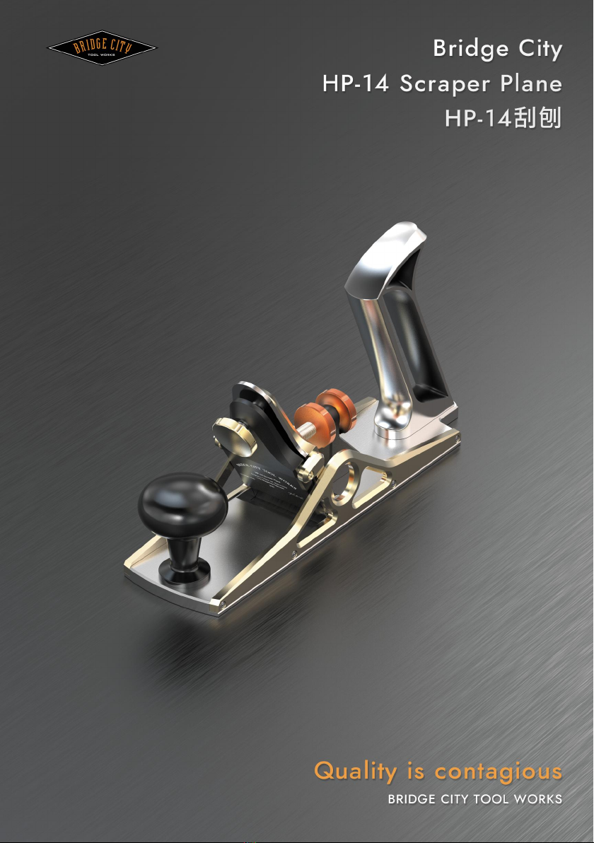
The Iron Clamping Mechanism pivots on the Frog Axle, which allows you to make angle
adjustments ranging from 88°~117°, as shown below in Fig. 4.
To raise the iron (down to 88 ° degrees), rotate the first lock wheel (near the frog)
CLOCKWISE, so that the wheel moves closer towards the frog. Then adjust the second
lock wheel (near the handle) CLOCKWISE, to raise the iron up to 88 ° degrees. Once
angle is set, rotate the first lock wheel COUNTER-CLOCKWISE to secure the Iron Angle
Adjustment Mechanism in place.
Vice versa, to lower the iron (up to 117° degrees), rotate the second lock wheel (near
the handle) COUNTER-CLOCKWISE before adjusting the first lock wheel (near the frog).
Once angle is set, rotate the tighten the second lock wheel to secure the Iron Angle
Adjustment Mechanism in place.
By rotating the lock wheel, this will adjust the scraping iron to the appropriate scraping angle,
which is based upon the hardness and roughness of the wood surface. Making test cuts will be
necessary to determine whether you have achieved the proper scraping angle. When properly
set-up, the iron should produce fine shavings rather than dust.
Fig. 4 Iron Angle Adjustment Range
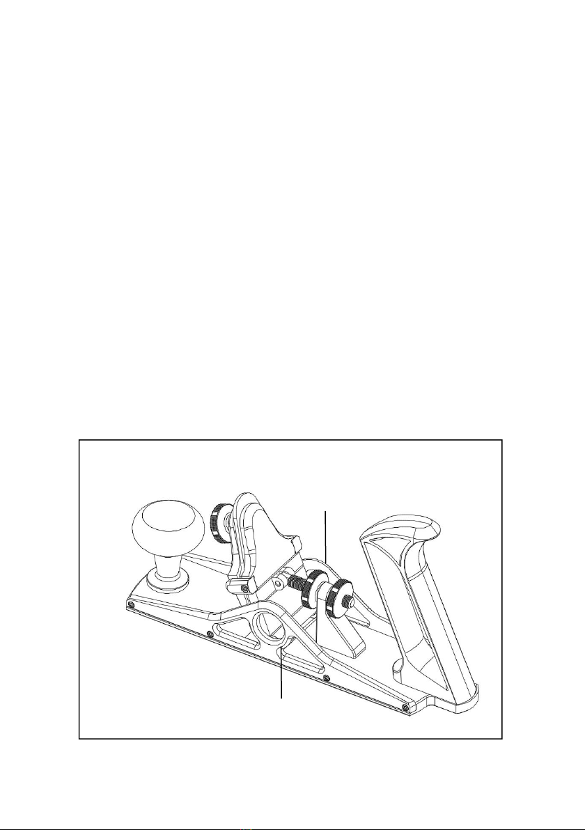
Adjusting scraping depth:
A single pass of the HP-14 Scraper Plane will produce exceedingly small shavings. In most cases,
the recommended scraping depth of the iron should measure 0.01mm. There are two methods to
achieve the correct scraping depth, which can be adjusted as follows:
Method A:
Place the HP-14 Scraper Plane on a flat surface such as a workbench. Rotate the lock wheel to
raise the iron to the desired scraping angle. Loosen the iron cap knob and adjust the iron so that
the edge is flushed with the table surface, and then tighten the iron cap knob.
Place the HP-14 Scraper Plane on the workpiece and adjust the lock wheel again, as shown in Fig.
5. While viewing the plane from the rear, rotate the lock wheel counterclockwise to increase the
scraping depth. There are six semi-circular cuts milled around the lock wheel, which can be used
as marks to complete fine adjustment. By rotating the lock wheel by 1/3 turn counterclockwise
will increase the scraping depth by 0.04~0.01mm.
4

NOTE: By gradually tilting the Iron Clamping Mechanism forward (towards the front of the plane),
this increases the scraping depth of the iron.
Fig. 5 Scraping Depth Adjusting (Method A)
Method B:
Place the HP-14 Scraper Plane on a flat surface such as a workbench. Rotate and adjust the lock
wheel to position the iron at the desired scraping angle. Using two filler gauges of the same
thickness, not exceeding 0.05mm, place them under the front and rear of sole of the plane.
Loosen the Iron Cap Knob and adjust the edge of the iron to be flush with the table surface, and
tighten the iron cap knob, as shown in Fig. 6.
Fig. 6 Scraping Depth Adjusting (Method B)
Rear View
Lock Wheel
Iron
Iron Ca
p
Knob
Frog Rotating Direction
Six Semi-circular Cuts of Lock Wheel
Filler Gau
g
e
Frog
Workbench
Filler Gau
g
e
Lock Wheel
Iron
Iron Ca
p
Knob
Frog
5

Iron
The HP-14 plane iron is made of hardened tool steel with a Rockwell hardness of 58 to 62. This
makes the iron suitable for working with all different types of hardwoods and difficult grain
patterns.
As shown in Fig.7, the iron must be installed where the beveled edge must be facing the frog
(towards the rear of the plane). Before using the plane, always ensure that the iron is properly
setup and secured to avoid damaging the plane iron! Refer to previous sections for setup and
adjustments of the iron.
Fig. 7 Iron Installment
NOTE: The iron is EXTREMELY SHARP. Please handle with care to prevent accidental injury.
Sharpening the Iron
NOTE:
Prior to first use, it is recommended that you sharpen and turn a hook on the edge of
the iron. A hook is a burr that forms at the edge of the iron allowing you to get more
aggressive shavings than a normal beveled or micro-beveled edge.
The iron included with the HP-14 Scraper Plane has been precision lapped to a surface
finish of 0.012 Ra (micrometers). There is no need to lap the back of the iron for
flatness.
Iron Ca
p
Frog
Iron
6

To achieve a sharp scraping iron, please refer to the following steps:
1. The HP-14 iron comes with a 45-degree factory ground beveled edge. If needed, start by
sharpening along the 45-degree edge until the bevel is smooth. This step can be omitted for
first-time use.
2. To add a micro-beveled edge, raise the iron an additional 2°~5° degrees and sharpen the edge
of the iron edge as shown in Fig. 8.1, until you achieve a sharp edge. The first two steps should
be similar to how you would typically sharpen or hone a traditional plane iron.
3. Once the iron is sharp, clamp the iron firmly in a vice. You will need to secure the iron vertically
so that the edge is pointed upwards in the vise, as shown in Fig. 8.2.
4. Using a honing rod (or a burnisher tool), with a Rockwell hardness higher than 65, hone the
iron along the cutting-edge direction as shown in Fig. 8.3. Start by tilting the honing rod
approximately 10°~20° degrees (as seen in Fig. 8.3) and run the honing rod along the edge. After
3 or 4 passes of the honing rod, slowly increase the angle of the honing rod while continuing to
hone along the edge. Repeat this process and stop once your honing rod is perpendicular to the
back of the iron, as shown in Fig. 8.4. This will give you a great hook for your scraping iron.
Note: When honing the iron, apply even downward pressure to keep the edge perpendicular
with the sides of the iron. An uneven or un-squared edge will be difficult to setup and use.
Fig. 8 Iron Sharpening
Iron
Hone
Iron
Vise
Iron
Honin
g
Rod
Iron
Honin
g
Rod
Fi
g
. 8.1 Fi
g
. 8.2
Fi
g
. 8.3 Fi
g
. 8.4
7

Care and Maintenance
Maintenance: After each use, always remember to clean the HP-14 Scraper Plane and retract the
iron so the edge does not protrude below the sole of the plane. Wipe off any abrasive paste, dust,
water stains, and fingerprints with a soft cloth after each use to avoid oxidization and rust from
forming.
Apply a light coat of oil on the plane iron to prevent rusting. Also, add a drop of light oil on the
adjustment lead screw and locking wheels to lubricate the parts from excessive wear.
Store: If you plan to store the HP-6FX Mini Multi-Plane for extended periods, we recommend
that you thoroughly clean the plane of any dust, moisture, oils, and fingerprints. Lubricate all
moving parts with a light coat of oil and wipe off any excess with a soft, clean cloth. Apply
protective layer of wax or anti-rust oil onto the surface of sole and iron and store the plane in a
dry and safe environment.
8

中文版本
9

HP-14 刮刨
恭喜您购买了 HP-14 刮刨。在使用此款新刮刨之前,请阅读以下使用方法和设置说明。
综述
HP14 刮刨是一款用于最终调平、修整大平面,用于修刮复杂木纹表面的手工工具。
刮刨的工作原理是刮削,而非切削、刨削,木料以小薄片、颗粒状或粉末状被剥离,而非切割撕裂木
纤维,正确使用 HP-14 刮刨可以使加工表面更加平整、更加细腻光滑。
HP-14 刮刨是一款可以在使用中获得快乐和舒适体验的手工工具
HP-14 刮刨由刨底,刨刀压紧机构,刨刀角度调节机构,刨刀,前、后把手构成,如图 1 所示。
刨底、后把手等零件为不锈钢材质,通过 CNC 加工中心制作而成,后把手采用了基于人体工程学的圆
弧设计,整体抛光处理。刨刀压紧机构,刨刀角度调节机构和刨底两侧的侧板采用铝合金材质,通过 CNC
加工中心制作,表面阳极氧化处理,既美观,又兼具较高的硬度。
。
图 1: HP-14 刮刨结构组成图示
刨刀角度调节机构
刨刀压紧机构
前把手
刨底
后把手
侧板
10

刮刨机构介绍
刨刀压紧机构:
HP-14 刮刨由刨刀压板、压紧旋钮和刀架组成。根据需要调节刨刀位置,旋转压紧旋钮,将刨刀牢牢
压紧在刀架平面上。
图 2: HP-14 刨刀压紧机构
刨刀角度调节机构:
HP-14 刮刨的刨刀角度调节机构是用于调节刮刨刨刀角度的机构。由调节支架、调节螺母和调节螺杆
构成。旋转调节螺母,推动刨刀压紧机构沿转轴旋转,确定刨削角度;刮削时,必须锁紧调节螺母在调节
支架两端,固定刨刀压紧机构。
图 3: HP-14 刨刀角度调节机构
刀架
压紧旋钮
刨刀压板
刨刀
调节支架
调节螺杆
调节螺母
转轴
11

刨刀角度调节机构的旋转角度范围:88°~117°,如图 4 所示。可根据木料的软硬程度和木料表面的粗
糙程度,旋转适当的刮削角度。
图 4: HP-14 刨刀角度调节范围图示
刨刀深度调节:
HP-14 刮刨的单次刨削量非常小,刨刀的切深以 0.01mm 为计量单位。可采用以下两种方式进行刨刀
深度调节:
① 将 HP-14 刮刨放置在台面上,旋转调节螺母,使刀架固定在期望的刮削角度,调节刨刀刃口与台面
齐平,锁紧压紧旋钮。将 HP-14 刮刨移至木料上,再次调节调节螺母,如图 5 所示,在后方视角,逆时针
转动调节螺母,可增加刨刀的刮削深度。调节螺母上加工了滚花和圆弧凹槽,将圆周分隔成 6 个均等区域,
可以以此为标记完成精细调节。调节螺母逆时针转动 1/3 圈,可以带动刀架组件转动微小的角度,进而增
加刨刀的刮削深度 0.04mm~0.01mm。
刮削深度随着刨刀角度增大而增加,增量逐渐减小。
图 5: HP-14 刨刀调节深度方案①图示
刀架
后方视角
调节螺母
刨刀
压紧旋钮
刀架旋转方向
调节螺母圆周 6 等分
12

② 将 HP-14 刮刨放置在台面上,旋转调节螺母,使刀架固定在期望的刮削角度,将两枚厚度适合,且
厚度相同的塞尺(建议塞尺规格不超过 0.05mm)分别放在 HP-14 刮刨刨底的前端和后端,调节刨刀刃口
与台面齐平,锁紧压紧旋钮。如图 6 所示。
图 6: HP-14 刨刀调节深度方案②图示
建议先进行测试切割,确定最佳的刮削角度和深度,最佳的刮削效果应该是产生细屑而不是灰尘。
刨刀
HP-14 刮刨的刀具均采用工具钢材料,通过硬化处理达到洛氏硬度 58~62。适合刮削各种硬木和纹理
复杂的工件表面。
如图 7 所示,HP-14 刮刨刨刀必须斜面向刀架方向安装,通过刨刀压紧机构锁紧。
图 7: HP-14 刨刀安装方向图示
注意: 刨刀非常锋利,小心拿放,防止出现意外伤害。
刨刀压板
刀架
刨刀
塞尺
刀架
平台
塞尺
调节螺母
刨刀
压紧旋钮
13

刨刀研磨
注意:在第一次使用 HP-14 刮刨之前,请按以下步骤研磨刨刀。
HP-14 刮刨刨刀的表面均经过精密研磨,因此平面度可达到 0.012RMS,不再需要研磨刨刀表面。
HP-14 刮刨刨刀是利用刃口的卷刃进行刮削,因此要达到优良的刮削效果,就要保证刨刀具有均匀的
卷刃。具体研磨方法按以下步骤:
①按常规刨刀研磨方法研磨,刨刀刃口出厂设置为 45°,沿 45°刃面研磨至光洁后(首次使用可省略此
步骤),按图 8 中①图所示角度精磨刃口部位,直至刃口锋利;
②将刨刀牢固的垂直装夹在台钳或工装上,如图 8 中②图所示;
③用洛氏硬度高于 65 的磨刀棒沿刃口方向如图 8 中③所示均匀推磨,角度逐渐减小最终与刨刀垂直,
获得平直均匀的卷刃,如图 8 中④所示。
注意:研磨时需保持刃口与两侧边的垂直。
图 8: HP-14 刨刀研磨图示
① ②
③④
刨刀
磨刀石
刨刀
台钳
刨刀
磨刀棒
刨刀
磨刀棒
14

维护和保养
维护
每次使用后需及时清理干净 HP-14 刮刨,将刨刀提起,收进刨底,并在调节螺杆和转轴上滴入一滴轻
质机油防止出现过度磨损。在每一次磨刀后及时用干净的软布擦除水渍和指纹。
储存
如果需要长时间储存 HP-14 刮刨,我们推荐清除刮刨上的木屑与灰尘,润滑所有运动零件并且擦除多
余的油脂和指纹。刨底、刨刀表面涂抹防护蜡或防锈油,置于干燥、安全的位置储存。
15


Table of contents
Other Bridge City Tools manuals

Bridge City
Bridge City HP-8 User manual

Bridge City
Bridge City DJ-3 User manual

Bridge City
Bridge City Chopstick Master User manual

Bridge City
Bridge City Signature Series User manual

Bridge City
Bridge City HP-12 User manual

Bridge City
Bridge City HP-9v2 User manual

Bridge City
Bridge City Chopstick Master User manual

Bridge City
Bridge City Pencil Precision PP-1 User manual

Bridge City
Bridge City HP-9v2 User manual