Bridgeview BALE KING BRX850 Programming manual

BALE KING BRX850
Bale Retriever
Operator's & Parts Manual
Last Updated: July 10, 2023
BRIDGEVIEW MANUFACTURING INC.
P.O BOX 4, HWY 22
GERALD, SASK. S0A 1B0
CANADA
Ph: 306-745-2711
Fax: 306-745-3364
www.bridgeviewmanufacturing.com

ii Bridgeview Manufacturing Inc.
Your Authorized Dealer
Your Serial Number
The Serial Number is located on the front of the Left Rail.

iii Bridgeview Manufacturing Inc.
TABLE OF CONTENTS
INTRODUCTION .............................................................................................................. 1
Warranty Information ..................................................................................................... 1
Safety Precautions........................................................................................................... 2
Hydraulic System Safety............................................................................................. 2
FEATURES .................................................................................................................... 3
Implement Tongue.......................................................................................................... 3
Axles............................................................................................................................... 3
Lifting Arm..................................................................................................................... 3
Bale Deck........................................................................................................................ 4
Adjustable Roll Over Stop.............................................................................................. 4
OPERATION...................................................................................................................... 5
Hooking up Machine................................................................................................... 5
Loading Bales ............................................................................................................. 5
Unloading Bales.......................................................................................................... 5
Unhooking Machine.................................................................................................... 6
MAINTENANCE............................................................................................................... 7
Lubrication...................................................................................................................... 7
Wheels and Tires............................................................................................................. 8
Tire Inflation and Rating............................................................................................. 8
Hub Removal.............................................................................................................. 8
Bearing and Seal Inspection........................................................................................ 9
Hub Installation........................................................................................................... 9
Sled Chain..................................................................................................................... 10
Cylinder Maintenance................................................................................................... 11
TRANSPORTATION....................................................................................................... 12
TROUBLESHOOTING GUIDE ...................................................................................... 13
FEATURES AND SPECIFICATIONS............................................................................ 14
PARTS MANUAL............................................................................................................ 15
Bale King BRX850....................................................................................................... 15
Front and Rear Deck..................................................................................................... 16
Rocking Axle Weldment Left (and Right).................................................................... 17
NOTE: Quantities are given as per side. For both sides, double the above quantities. 17
Axle Install.................................................................................................................... 18
Spindle and Rim Assembly (Standard Wheels)............................................................ 19

iv Bridgeview Manufacturing Inc.
Spindle and Rim Assembly (Oversized Wheels).......................................................... 20
6500 Lb Spindle Assembly........................................................................................... 21
A Frame ........................................................................................................................ 21
Hydraulic and wiring diagram.......................................................................................... 42
Conveyor Chain motor.................................................................................................. 42
Tilt Cylinder.................................................................................................................. 44
Loading arm.................................................................................................................. 44
Light Diagram............................................................................................................... 46
NOTES.............................................................................................................................. 47

1 Bridgeview Manufacturing Inc.
INTRODUCTION
Thank you for purchasing a Bale King BRX850 bale retriever. With the proper
operation and service as outlined in this manual, the Bale King will provide you with
years of trouble-free operation.
This is a complete safety, operation, and parts manual for the Bale King BRX850.
The manual covers in detail how to use your new bale retriever safely and effectively.
The procedures outlined in this manual should be followed to ensure safe operation and
longevity of your machine. The parts manual covers all parts you may need to order in
case of accident or breakdown. Please read completely through this manual before
beginning operation of your new machine.
Warranty Information
Bridgeview Manufacturing Inc. provides warranty on the BALE
KING BRX850 series to its original owner for a period of two years
from the date of purchase according to the following provisions:
Normal Farm Use
Commercial, Government, or Rental Use
First year warranty covers parts* and labour.
Second year warranty covers parts* only.
One year warranty covers parts* and labour.
•Warranty covers defects in material and workmanship.
•Warranty does not cover damage to the machine and its components if the
operator does not follow the operating instructions in the operator’s manual.
•Warranty does not cover normal wear and tear.
•Warranty will be VOID and Bridgeview Manufacturing Inc. is not liable in any
way if the Bale King BRX850 is used for any purpose other than its intended use.
•Tire warranty is covered by the Tire Manufacturer.
All warranty service must be handled through an authorized Bale King dealer. Any
repairs after the warranty period are the owner’s responsibility. Any overtime requested
by the owner to have the machine repaired during the warranty period will be the owner’s

2 Bridgeview Manufacturing Inc.
responsibility. Warranty is at the dealership and NO travel time will be reimbursed.
Freight costs associated with warranty repairs are not reimbursable. Warranty does not
cover downtime. Warranty will be VOID if any component is altered or modified in any
way, unless written permission is given by Bridgeview Manufacturing.
Bridgeview Manufacturing Inc. reserves the right to make changes or
improvements at any time without notice or obligation.
Safety Precautions
The following safety precautions MUST be followed to
ensure safe operation of the Bale King BRX850.
•ALWAYS turn OFF the tractor when leaving the
operating platform.
•DO NOT walk or move under the lifting arm when in the upward position.
•ALWAYS stay clear of the sled while its moving.
•DO NOT climb under deck when in the raised position.
•ALWAYS turn off the tractor when cleaning the machine, or hooking and
unhooking the machine.
•ALWAYS use safety chain when towing the machine on roadways.
Hydraulic System Safety
WARNING: Pressurized hydraulic fluid
can cause serious injury.
•When working with hydraulic
equipment, eye and hand protection
should be worn.
•Do not test for leaks with bare hands.
•Relieve any pressure before removing a hose or fitting.
•Never work under components raised by hydraulic equipment unless supported
externally.

3 Bridgeview Manufacturing Inc.
FEATURES
Implement Tongue
The adjustable hitch on the Bale King is a cast single tongue with optional clevis insert
(BMI #25540). This allows for use with tractors equipped with a hammer strap or with a
single drawbar. The design of the tongue allows the machine to move over rough terrain
without bending the draw pin. NOTE: The hammer strap insert is to be used for
transport ONLY.
ATTENTION: Set the drawbar to 16 inches behind the PTO shaft to ensure no stress is
placed on the hydraulic hoses. Adjust the hitch height such that the machine sits level
when attached to the tractor.
Axles
The Bale King BRX850 is equipped with two tire rocking tandem axle with 14L-16.1 SL
and an option to oversize the tires to 16.5L-16.1 (BMI #34541).
Lifting Arm
The lifting arm on the BRX850 can
handle up to 6.5 ft round bales. The
arm can be adjusted to accommodate
smaller bales by loosening lock nuts
for the upper bolts, on the back of the
fork tine, and back off the bolts.
Loosen off the lower bolts, on the
back of the fork tine. Move the fork
tine to the desired position, and retightening the bolts and nuts. The quarter-turn arm
allows for loading from any direction, rotating the bale to the correct orientation for
loading. The Arm is equipped with a spring-loaded float to allow the arm to ride over
rough terrain without causing damage to the machine.

4 Bridgeview Manufacturing Inc.
Bale Deck
The bale deck is designed to carry up to eight
62”long round bales. A pusher sled is used
move bales back on the deck allowing more
bales to be loaded. The machine is equipped
with hydraulic stops to prevent damage to
machine at the end of the pusher’s range of
motion.
When the machine is fully loaded a red indicator
flag will pop out on the inside of the right deck
rail.
Adjustable Roll Over Stop
The Roll Over Stop can be adjusted
to stop smaller bales sooner. Remove
the top Bent Pull Pins and rotate the
Roll Over Stop to the desired position
and reinstall the Bent Pull Pins.

5 Bridgeview Manufacturing Inc.
OPERATION
Hooking up Machine
•Connect machine to tractor drawbar.
•Shut off the tractor.
•Connect hydraulic hoses and light plug to tractor.
•Retract jack fully, Remove the jack from the A Frame and secure it on the jack
stub on the Bed Rail.
•Attach safety chain to the tractor. Always ensure the safety chain is properly
installed. There should be enough slack to allow for turning, but not so much that
the chain drags on the ground.
•Visually inspect machine to ensure everything is in proper working condition.
•Start tractor and test lifting arm, deck tilt, and pusher movement.
Loading Bales
•Drive along left side of bale.
•Lifting arm will rotate bale to correct orientation.
•Drive until bale is against back of lifting arm
frame.
•Lift arm until bale rolls onto deck.
•Operate pusher to move the bale back far
enough to clear the lifting arm.
•Load bales until the full load indicator is tripped
and the red indicator is visible inside the right
bed rail
Unloading Bales
•Raise deck up.
•Using the pusher, unload the bales
•Lower deck once all bales are unloaded and
return pusher to the front of the machine.

6 Bridgeview Manufacturing Inc.
Unhooking Machine
•Shut off the tractor.
•Disconnect hydraulic hoses, light plug, and safety chains from tractor.
•Move the jack back onto the A Frame and secure it. Extend until the machine is
resting on the jack.
•Disconnect machine from tractor drawbar.
There are three sets of hydraulic hoses to connect to the tractor, each with a marking to
distinguish which component it controls. The hoses should be connected to the tractor to
suit the operator's preference.
Large hose with yellow marker:
Pusher
Medium hose with red marker:
Lifting Arm
Medium hose with blue marker:
Deck Lift Cylinder
Note: Always set the tractor's hydraulic flow at a lower rate and adjust it upward until
the desired speed is reached.

7 Bridgeview Manufacturing Inc.
MAINTENANCE
Lubrication
The BRX850 needs be lubricated using good quality grease, at the following locations at
the specified intervals. Chain should be lubricated with quality chain oil.
Location
Timeline
A
Lifting Arm Pivot (x 2)
200 Bales (or 10 hours)
B
Lifting Arm Cylinder (x2)
C
Deck Lift Cylinder (x2)
1000 Bales (or 50 hours)
D
A Frame Pivot(x2)
E
Deck Pivot (x4)
F
Deck Chain
G
Wheel Hubs (x 4)
Seasonally (or 300 hours)

8 Bridgeview Manufacturing Inc.
Wheels and Tires
Examine tires for cuts, bruises, cracks, bulges, and penetrations.
Tire Inflation and Rating
Wheel bearings should annually be lubricated and inspected for any required adjustment.
Inspect more often for extensive traveling. Proper tire inflation will help to alleviate
puncture problems when towing and operating on rough terrain.
Standard Tires
Oversized Tires
Check for proper tire inflation
52 PSI
36 PSI
Replace any damaged tires
14Lx16.1-12 ply
16.5L-16.1 -10 Ply
Check and tighten wheel bolts on a
regular basis
125 ft-lb
125 ft-lb
Note: When inflating tires, use a clip-on chuck and extension hose long enough to
allow you to stand to one side and NOT in front of or over the tire assembly.
Note: Warranty does not cover damaged rims and hubs due
to loose wheel bolts or flat tires. Tire warranty is covered by
the tire manufacturer.
Hub Removal
Procedure for maintenance and replacing hubs.
1. Elevate and support the walking axle.
2. Check for excessive wheel end play by pulling the tire assembly towards you
and by pushing the assembly away from you. Slight end play is acceptable.
3. Rotate tire slowly forwards and backwards. The wheel assembly should turn
freely and smoothly. If there is excessive wheel end play, restriction to rotation,
noise, or "bumpy" rotation, the bearing unit needs to be replaced.
4. Remove the wheel.
5. Remove the dust cap by carefully prying around the flange of the cap.

9 Bridgeview Manufacturing Inc.
6. Remove the cotter pin from the spindle nut.
7. Unscrew the spindle nut and remove the spindle washer.
8. Remove the hub from the spindle, being careful not to allow the outer bearing
cone to fall out. The inner bearing cone will be retained by the seal.
9. Clean all the part and make sure the bearing and the spindle will not get
contaminated.
Bearing and Seal Inspection
•If the bearing shows signs of pitting or corrosion then the
bearing must be replaced. The bearing cup inside the hub
must be inspected. Bearings should be replaced in sets.
•Repack all good bearings with grease.
•Whenever the hubs are removed, inspect the seal to ensure that it
is not nicked or torn and is still capable of properly sealing the
bearing cavity. If there is any question of condition, replace the
seal.
Hub Installation
If the hub has been removed or bearing adjustment is required, the following adjustment
procedure must be followed:
1. After placing the hub, bearings, washers, and spindle nut back on the axle
spindle in reverse order as detailed in the previous section on hub removal, rotate
the hub assembly slowly while tightening the spindle nut appropriately 50 lbs.-ft.
2. Then loosen the spindle nut to remove the torque. Do not rotate the hub.
3. Tighten the spindle nut until it is snug and install cotter pin.
4. Pack hub full of grease and install dust cap.
5. Install the wheels and fasten the bolts. Torque bolts to 125 ft-lbs

10 Bridgeview Manufacturing Inc.
Sled Chain
•Lubricate chain every 50 hours of operation and
before long periods of storage. Always use quality
chain oil when lubricating the drive chain.
Check chain tension at center of deck by applying 30
lbs of force on the chain. Correct tension is measured as
1 inch deflection between chain and deck. Adjust chain
tension using the following steps:
1. Loosen the lock nut
2. Turn tension nut accordingly until
correct chain tension is acheived.
3. Tighten Lock nut.

11 Bridgeview Manufacturing Inc.
Cylinder Maintenance
To remove the hydraulic cylinders for repair or maintenance, follow these steps:
•Fully lower the deck (or lifting arm) and unhook hydraulic lines. Be sure there is
no pressure on the lines and mark the line locations so there is no confusion when
reinstalling the cylinders. Check hydraulic schematics.
•Remove locking bolts for cylinder pins and remove cylinder pins.
•To reinstall, reverse the removal procedure.
NOTE: Always cover exposed cylinder shafts with grease to avoid rusting of shafts if
the unit is not used for extended periods of time. Rusted cylinder shafts are NOT
covered by warranty
NOTE: Check all hoses and fittings periodically for leaks. Tighten or replace any
dripping components or any worn out hoses.

12 Bridgeview Manufacturing Inc.
TRANSPORTATION
The Bale King BRX850 can be safely towed on public roads, following these precautions:
•Tow vehicle must be rated for at least 6490 lb gross, 1930 lb tongue when
machine is empty, and 22500 lb gross, 5887 lb tongue when loaded.
•NEVER exceed 40 km/h (25 mph).
•ALWAYS ensure that the safety
chain is properly installed
•Tow vehicle must have a 7-pin
round trailer plug
•Plug in lights and check for proper
function (flashing amber lights,
solid red lights)
•Ensure that the supplied SMV (Slow Moving Vehicle) sign is clearly visible from
the rear
•Raise the lifting arm completely.
•Ensure that the hydraulic hoses are properly secured.

13 Bridgeview Manufacturing Inc.
TROUBLESHOOTING GUIDE
Problem
Possible Cause
Remedy
Pusher stops
Unexpectedly
Broken drive sprocket
•Replace failed part.
Hydraulic stop not releasing
•Replace failed part
Dirt Binding Drive Chain
•Clean out built up dirt and debris front
drive sprocket
Chain jumped off idler wheel
•Refer to next line.
Chain jumps off
idler wheel
Chain Tension not Properly
adjusted
•Place chain back on idler wheel and
correctly adjust the tension
Poor fork operation
Air In Hydraulic System
•Raise fork fully holding hydraulic lever for
several seconds.
Scored Cylinder Shaft and
damaged Seal
•Check for scoring on cylinder shaft and
replace shaft if necessary
•Replace cylinder seal if damaged
Poor deck tilt
operation
Air In Hydraulic System
•Lower deck fully holding hydraulic lever
for several seconds.
Scored Cylinder Shaft and
damaged Seal
•Check for scoring on cylinder shaft and
replace shaft if necessary
•Replace cylinder seal if damaged
Lights not in
Position
Broken or Missing Shear
Bolt
•Replace missing or broken 3/8”x 1”Bolt
and 3/8”Nylon lock Nut

14 Bridgeview Manufacturing Inc.
FEATURES AND SPECIFICATIONS
Dimensions and Specifications
Max Bale Weight
2000 lbs
Weight (Empty)
6490 lbs
Maximum Weight (Loaded)
22500 lbs
Drawbar Weight (Empty)
1932 lbs
Maximum Drawbar Weight
5887 lbs
Overall, Height (Lifting Arm Up)
158"
Overall, Height (Lifting Arm Down)
61"
Tread Width (on Centres)
95"
Transport Width (arm Up)
108"
Max Width (Arm Down)
216.25"
Length
590"
Single Hydraulic Deck Tilt Cylinder
4" x 14" x 2" Rod
Single Hydraulic Lifting Arm Cylinder
4" x 14" x 2" Rod
Tire Size (Standard Tire)
14L-16.1 SL 12 Ply
Tire Size (Oversized Tire Option)
16.5L-16.1 10 Ply
Tire Inflation (Standard Tires)
52 PSI
Tire Inflation (Oversized Tire Option)
36 PSI
Wheel Nut Torque
125 ft-lbs
Drive Chain Type
C2080H
Horsepower Requirement
120
Required Number of Hydraulic Remotes
3

15 Bridgeview Manufacturing Inc.
PARTS MANUAL
Bale King BRX850
**THIS MANUAL IS FOR SERIAL NUMBERS 26227 & UP ONLY.
FOR PRIOR SERIAL NUMBERS, CONTACT BRIDGEVIEW DIRECTLY. **
Per ID#: NSS=Not Sold Separately
Item #
Description
QTY.
1
Front Deck
1
2
Rear Deck
1
3
A Frame
1
4
Pusher
1
5
Lifting Arm
1
6
Rocking Tandem Axle
2
7
Wheel Assembly
4
8
Rollover Stop
1

16 Bridgeview Manufacturing Inc.
Front and Rear Deck
Item #
Description
ID number
QTY.
1
¾” x 2”Bolt
13800
24
2
3/4" Stover Lock Nut
11823
24
3
Front Deck
NSS
1
4
Rear Deck
NSS
1
Table of contents
Other Bridgeview Farm Equipment manuals

Bridgeview
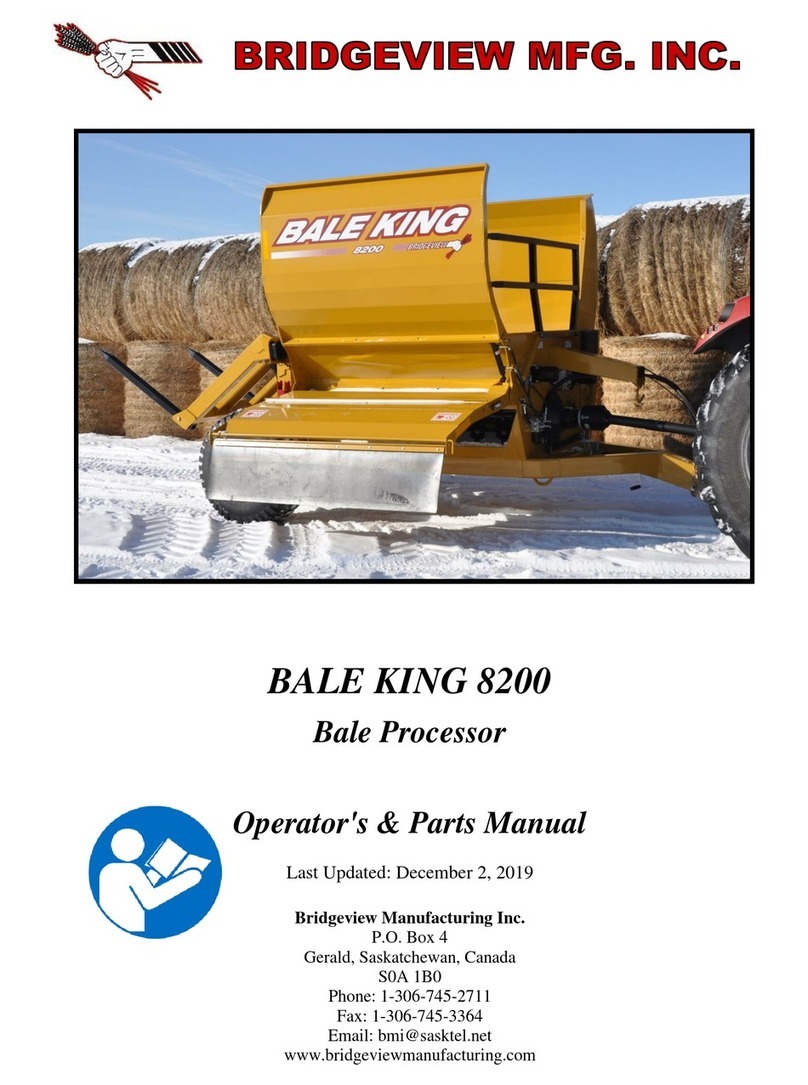
Bridgeview BALE KING 8200 Programming manual

Bridgeview
Bridgeview BALE KING 5100 Programming manual

Bridgeview
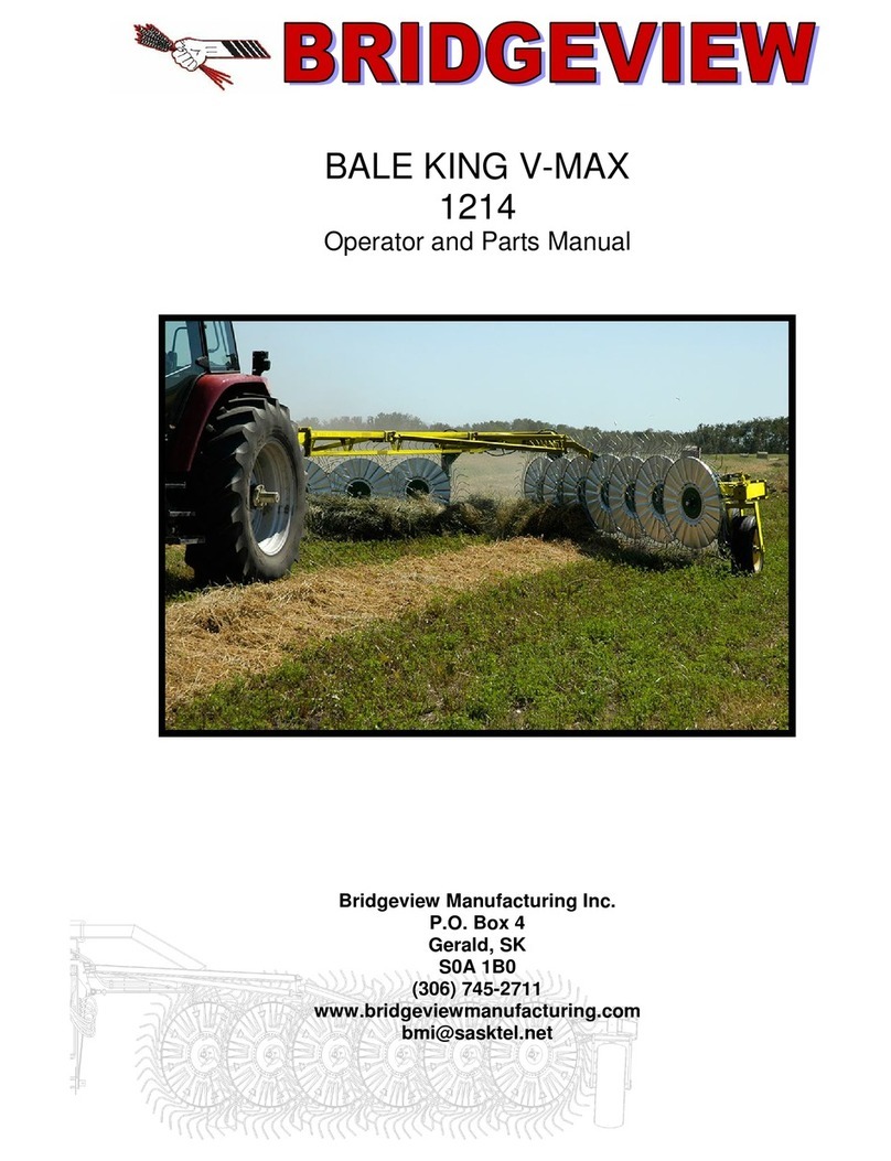
Bridgeview BALE KING V-MAX 1214 Product manual

Bridgeview
Bridgeview Bale King 6100 Programming manual

Bridgeview
Bridgeview BALE KING 5300 Series Programming manual

Bridgeview
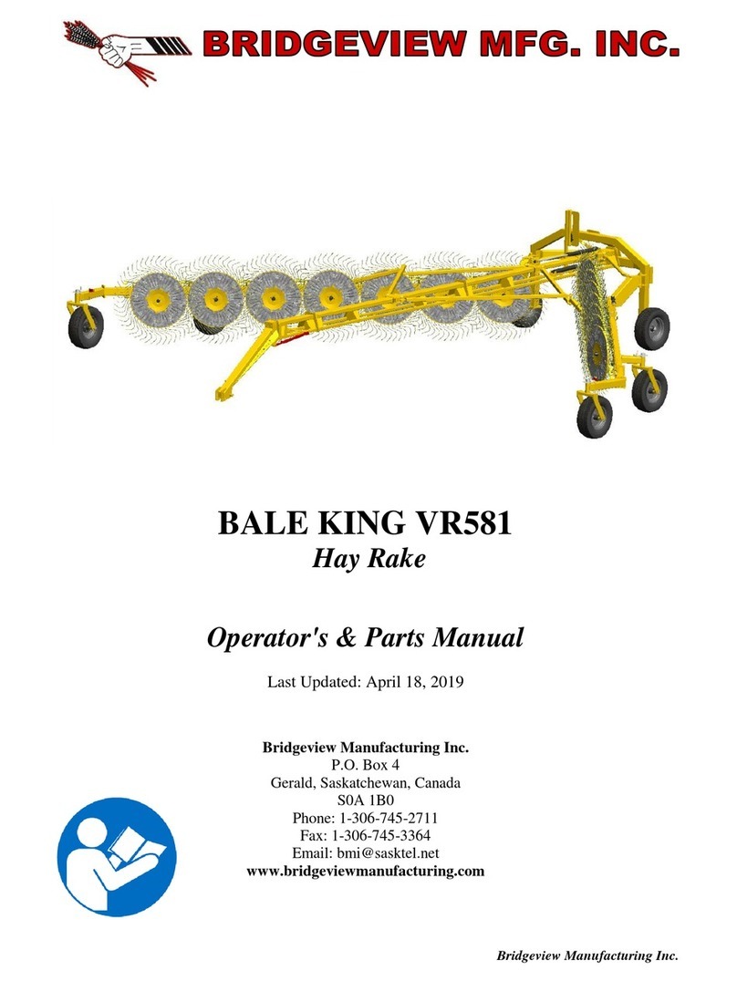
Bridgeview BALE KING VR581 Programming manual

Bridgeview
Bridgeview BALE KING 7400 User manual

Bridgeview
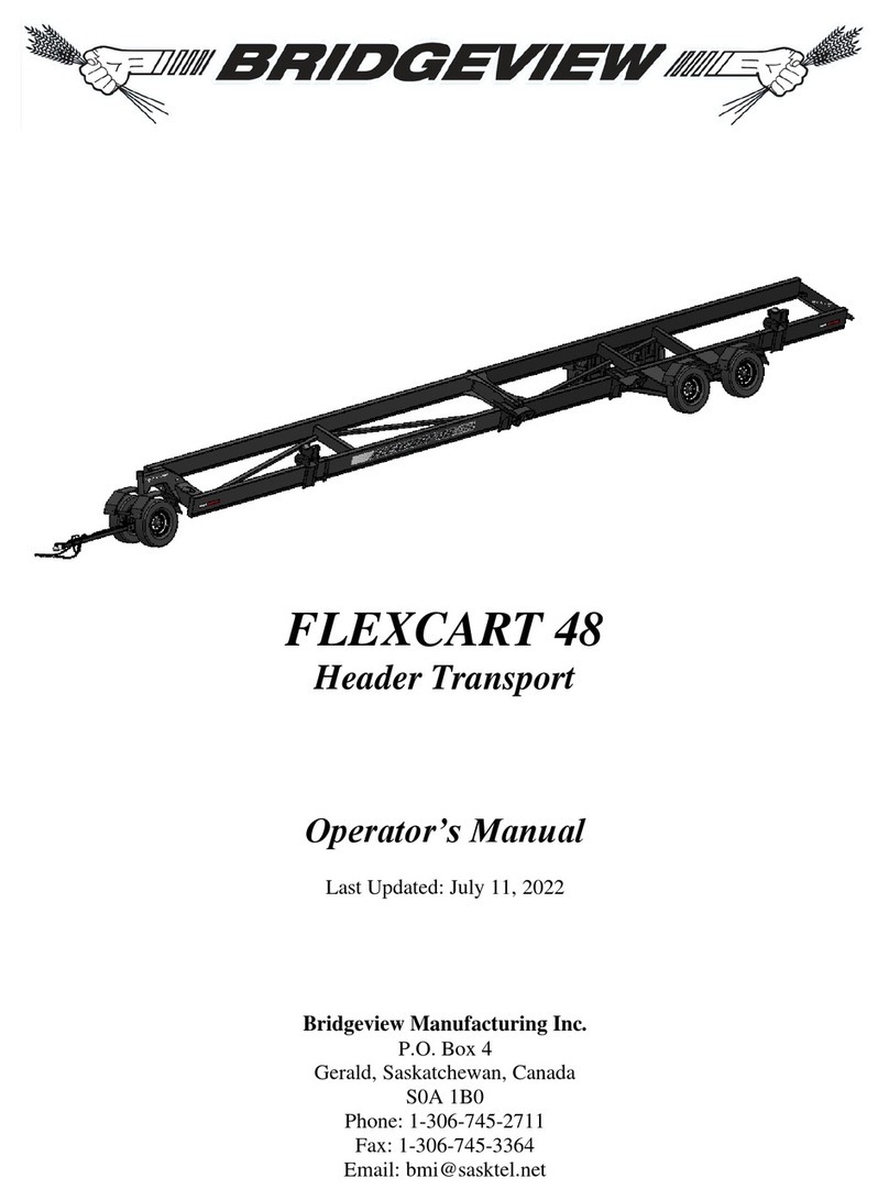
Bridgeview FLEXCART 48 User manual

Bridgeview
Bridgeview BALE KING 8300 User manual

Bridgeview
Bridgeview BALE KING 5300 Series Programming manual