Bridgeview BALE KING 5100 Programming manual

BALE KING 5100/5100TR
Bale Processor
Operator's & Parts Manual
Last Updated: August 11, 2015
Bridgeview Manufacturing Inc.
P.O. Box 4
Gerald, Saskatchewan, Canada
S0A 1B0
Phone: 1-306-745-2711
Fax: 1-306-745-3364
Email: bmi@sasktel.net
www.bridgeviewmanufacturing.com

Bridgeview Manufacturing Inc.
ii
The Serial Number is located the front tub panel, next to the operator manual box.
Your Authorized Dealer
Your Serial Number

Bridgeview Manufacturing Inc.
iii
TABLE OF CONTENTS
INTRODUCTION ........................................................................................................................................1
Safety Precautions .......................................................................................................................1
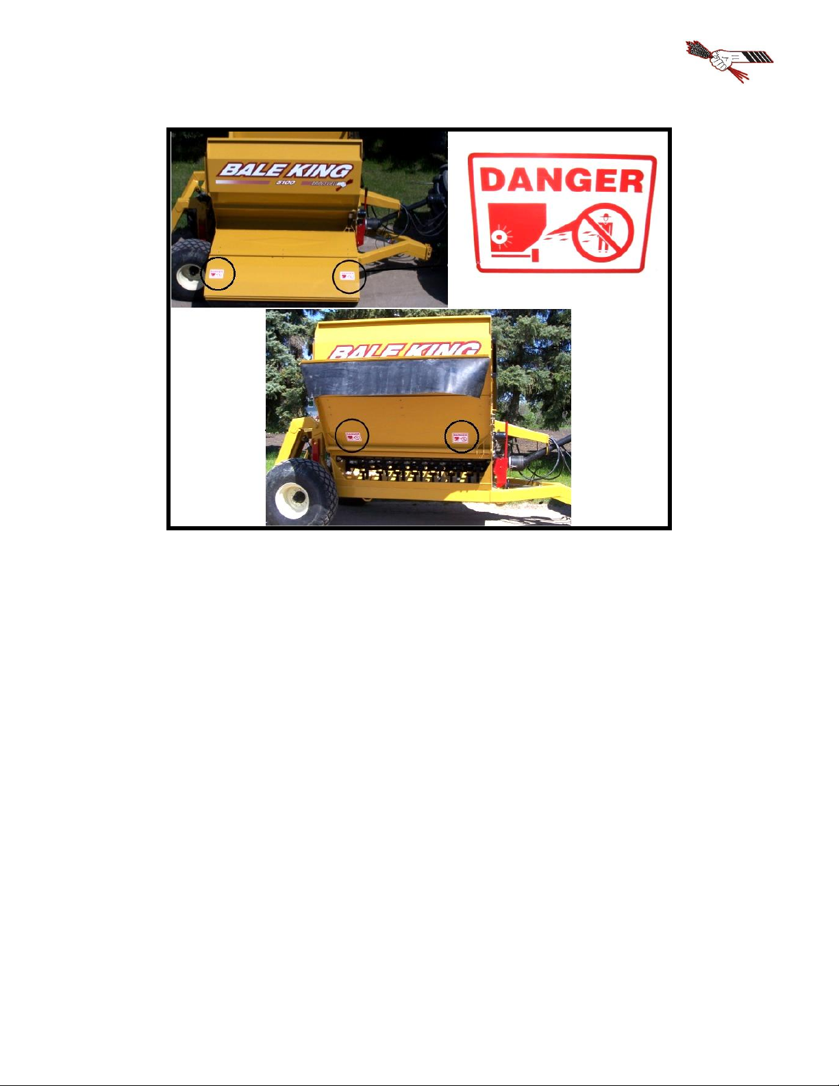
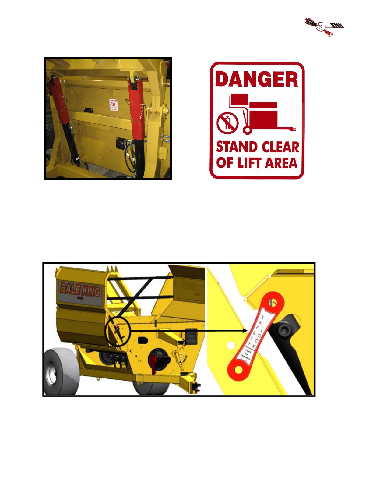
Safety Decals...............................................................................................................................2
FEATURES & OPERATION.......................................................................................................................5
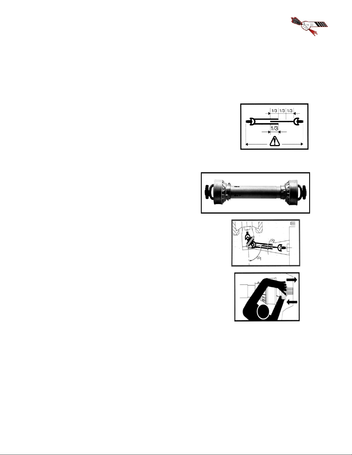
Power Take-off............................................................................................................................5
Hydraulics....................................................................................................................................9
Cylinder Maintenance................................................................................................................10
Implement Tongue.....................................................................................................................10
Rear Fork Tines.........................................................................................................................11
Hoop Grate Adjustment.............................................................................................................11
Hoop Grate Adjustment.............................................................................................................12
Deflector....................................................................................................................................13
Agitators....................................................................................................................................16
Loading Bales............................................................................................................................17
Optional Diverter Kit.................................................................................................................18
Optional Fine Chop Kit .............................................................................................................19
Optional Total Ration Grain Tank (5100TR)............................................................................20
Lubrication and Maintenance....................................................................................................22
Tire Inflation and Rating ...........................................................................................................24
Twine Removal..........................................................................................................................25
Rotor and Flail Replacement.....................................................................................................26
Transportation............................................................................................................................27
Trouble-shooting Guide.............................................................................................................28
Features and Specifications.......................................................................................................29
PARTS MANUAL......................................................................................................................................30
Jack & Hitch..............................................................................................................................30
Wheels & Hub...........................................................................................................................31
Rotor & Drive Components.......................................................................................................32
Gearbox .....................................................................................................................................33
PTO Shaft..................................................................................................................................35
Twine Cutter..............................................................................................................................36
Grates.........................................................................................................................................37
Agitators....................................................................................................................................38
Wings & Front Rack..................................................................................................................39
Rear Forks .................................................................................................................................40
Deflector & Hose Cover............................................................................................................42
Front Tub Components..............................................................................................................44
PTO Holder ...............................................................................................................................46
Rear Tub Components...............................................................................................................47
Slow Moving Vehicle (SMV) Sign Kit.....................................................................................48
Decals........................................................................................................................................49
Fine Chop ..................................................................................................................................50
Diverter Control Box.................................................................................................................52
Total Ration Grain Tank............................................................................................................54
HYDRAULIC AND ELECTRICAL SCHEMATICS................................................................................57
Hydraulics..................................................................................................................................57
Lights & Electrical.....................................................................................................................67
NOTES........................................................................................................................................................71

Bridgeview Manufacturing Inc.
1
INTRODUCTION
Thank you for purchasing a Bale King bale processor. With the proper operation and service as
outlined in this manual, the Bale King will provide you with years of trouble free operation.
This is a complete safety, operation and parts manual for the Bale King 5100. The
manual covers in detail how to safely and effectively use your new processor. The procedures
outlined in this manual should be followed to ensure safe operation and longevity of your
machine. The parts manual covers all parts you may need to order in case of accident or
breakdown. Please read completely through this manual before beginning operation of your new
machine.
Safety Precautions
The following safety precautions MUST be followed to ensure safe operation of the Bale
King Bale processor.
•ALWAYS turn OFF the tractor when leaving the operating platform.
•DO NOT stand in front of the discharge chute while the machine is running.
•DO NOT walk or move under the bale forks when they are in the upward position,
unless the cylinder safety lock is in place.
•DO NOT enter the machine while in operation.
•DO NOT clean machine while in operation.
•DO NOT stick any device into the machine to clear debris while the machine is in
operation.
•ALWAYS turn off the machine when cleaning the machine, removing twine, or
hooking/unhooking the machine
•ALWAYS use safety chain when towing the machine on the highway.
•DO NOT operate if any part of the PTO safety shielding is missing or is not secured.

Bridgeview Manufacturing Inc.
2
Safety Decals
Power Take-off
The operator must obey all safety labels and must maintain the proper shielding. A high
percentage of drive-line injuries occur when safety shielding is missing or not functioning
properly.
DANGER: Contact with a rotating drive-line can cause serious injury or death.

Bridgeview Manufacturing Inc.
3
Discharge
DANGER: Do not stand on the discharge side of the machine while it is in operation.

Bridgeview Manufacturing Inc.
4
Rear Fork Lift Area
DANGER: Stand clear of lift area. Do not stand under the forks unless safety locks are
installed.
Deflector Safety Lock: Unlock for Operation, Lock for Transport and Storage.

Bridgeview Manufacturing Inc.
5
FEATURES & OPERATION
Power Take-off
The Bale King bale processor has a PTO shaft which is splined on both ends. The
implement end uses a 1-3/4"-20 spline with wedge lock bolts. Install onto the gearbox and
tighten the wedge bolts. The bolts should be torqued to 160 ft-lb and re-torqued after 8 hrs of
use.
The tractor end comes standard with a 1-3/8"-21 spline quick detach constant velocity
joint. An optional 1-3/4"-20 spline yoke is available through your Bale King dealer.
The Bale King processor is designed to use a minimum of 75 HP. The drive shaft is
shear-bolt protected. The machine must be operated at 1000 PTO RPM.
NOTE: Spread yokes and twisted drive shafts are signs of OVERLOAD, not a manufacturer’s
defect and therefore not covered by warranty.
•DO NOT operate the machine using a spline adaptor. Use of adaptors will void
warranty due to damage caused to the tractor PTO, PTO driveshaft, or implement.
•DO NOT operate at 540 rpm, or use any kind of adaptor to connect to a 540 rpm spline.
•Always ensure that the PTO shaft is attached securely to the tractor. When the processor
is not hooked to the tractor, store the shaft on the PTO holder.
•DO NOT transport the processor without securing the PTO shaft. It may bounce off the
holder and be damaged.
•Always ensure that the drawbar is adjusted to 16” from the end of the tractor PTO shaft
to the center of the hole in the drawbar.
Operation
To engage the rotor for processing a bale, be sure the PTO shaft is properly connected to the
tractor. Engage the PTO at idle. After the PTO is fully engaged, increase PTO speed until it
reaches 1000 RPM.
The processor must not run at any speed less than 1000 PTO RPM as it may result in the
flails springing back against the rotor after they come in contact with the bale. This “backslap”

Bridgeview Manufacturing Inc.
6
may cause flails to fatigue and excessive vibration which may cause the bearings to fail. Bales
may be dumped into the tub while the rotor is stopped or while it is running.
Shear Bolt
All new Bale King processors are equipped with a shear bolt clutch located at the implement
end of the PTO shaft. The correct size shear bolt is 3/8 x 2” Grade 5. Any other size or grade
will damage the shear assembly. Spare shear bolts are shipped with each new machine and are
stored along the front top lip of the tub.
If your shear bolt is shearing excessively you may be over-loading the machine. If this
occurs raise the grate assembly to make the machine less aggressive, or roll the bale more
slowly. Always ensure that your machine is running at 1000 PTO RPM.
NOTE: Please consult your local dealer to help pinpoint any problems.
PTO Holder
A PTO shaft holder is standard with your new
Bale King, for safe storage of the PTO shaft
when the processor is not in use.
When unhooking the PTO shaft from
the tractor, lift the free end of the PTO shaft up
and place it in the holder provided. This will
keep the shaft away from the hitch when
hooking the tractor to the machine and keep it
clear from snow and ice.
The hydraulic hoses may need to be adjusted to best fit your tractor, to avoid damage
from rubbing on the PTO shaft shield. This can be done by loosing the bolt on top of the plastic
hose clamp, then pushing or pulling on the hoses to adjust the length.

Bridgeview Manufacturing Inc.
7
PTO Use and Maintenance
Shut OFF the tractor engine and remove the key before doing any maintenance on the machine.
Use ONLY genuine Weasler parts when replacing any worn or damaged PTO components.
Length:
Confirm the minimum and maximum working lengths of the drive-
line. The telescoping tubes must overlap at least 1/3 of their length
when in use. The PTO is designed to be used with a drawbar length
of 16" from the end of the PTO shaft. Adjust your tractor
accordingly.
Shielding:
Be sure that the shielding is not damaged and rotates
freely on the drive shaft.
Working Angles:
Constant Velocity joints can operate up to 80 degrees for short
periods of time. Do not operate for long periods on sharp angles.
Attachment:
Be sure the drive-line is properly attached and all bolts and screws
are tight on the implement input shaft and on the tractor PTO shaft.
Storage:
When not in use, cover or protect the drive shaft from the weather. When removed from the
machine store both halves together to prevent damage. Check all components for proper
function and lubrication before use.

Bridgeview Manufacturing Inc.
8
BEFORE ATTEMPTING ANY REPAIR PROCEDURES,
ALWAYS USE APPROPRIATE EQUIPMENT SUCH AS
SAFETY GLASSES, SAFETY SHOES, AND GLOVES
Shield Removal:
•To remove the shield, pop out the red snap, then rotate
the guard on the bearing to line up the three tabs with
the openings and pull it off away from the knuckle
joint.
•Remove the nylon bearing from the shaft by spreading
it open.
Shield Assembly:
•Be sure to lubricate the groove in the inner yokes where the shield
bearing rides. Reinstall shields in the reverse order that they were
removed.

Bridgeview Manufacturing Inc.
9
Hydraulics
WARNING: Pressurized hydraulic fluid can
cause serious injury.
•When working with hydraulic equipment,
eye and hand protection should be worn.
•Do not test for leaks with bare hands.
•Relieve any pressure before removing a
hose or fitting.
•Never work under components raised by hydraulic equipment unless supported externally.
There are three sets of hydraulic hoses to connect to the tractor. Each hose has a coloured marker
to identify its function. They should be connected at best convenience for the tractor's controls.
Note that the hoses are paired by colour and the following tables show the operation when
pushing oil into the hose with the longer marker.
5100 - 3 Remotes
Hose Marker
Function
Long Red
Turn agitators clockwise
Long Blue
Lift rear fork
Long Yellow
Lift discharge deflector
An optional diverter kit (BMI # 25091) is available to allow the Bale King 5100 to run using
only two sets of hoses. The function is then determined by a control box, mounted in the cab of
the tractor.
5100 - 2 Remotes
Hose Marker
Function
Long Red
Turn agitators clockwise
Long Blue
Lift rear fork or deflector
Always set the tractor's hydraulic flow at a lower rate and adjust it upward until the desired speed
is reached. Excessive oil flow may damage the flow divider cartridge.

Bridgeview Manufacturing Inc.
10
Cylinder Maintenance
The hydraulic cylinders are easily removed for repair or maintenance
simply by:
•Lowering the fork (or deflector) to the down position and
unhooking the hydraulic lines. Be sure there is no pressure on
the lines and mark the line locations so there is no confusion
when reinstalling the cylinders. Check hydraulic schematics.
•Removing the cotter pin closest to the frame of the machine and
sliding the cylinder pins out
•To reinstall, reverse the removal procedure
NOTE: Always cover exposed cylinder shafts with grease to avoid rusting of shafts if the unit
is not used for extended periods of time. Rusted cylinder shafts are NOT covered by warranty
NOTE: Check all hoses and fittings periodically for leaks. Tighten or replace any dripping
components or any worn out hoses.
Implement Tongue
The adjustable hitch on the Bale King features a cast single
tongue with hammer strap insert. This allows for use with
tractors equipped with a hammer strap or with a single
drawbar. It also allows the machine to move independently
over rough terrain without bending the draw pin.
•Make sure that the drawbar is set to 16 inches behind
the PTO shaft for proper PTO length.
•Adjust the hitch height to match the drawbar height and allow the machine to sit level.
•DO NOT install the insert if using a tractor with a hammer strap as this will bend the
hitch pin
NOTE: Make sure that the jack in on the outside stub for lifting, and the inside stub during
transport. DO NOT lift the machine with the jack on the inside stub.

Bridgeview Manufacturing Inc.
11
Rear Fork Tines
The rear fork bale tines can be adjusted side to side by removing the
pin connecting the tine to the machine and replacing the tine in the
other available gap. Always use tines in the same position on either
side to keep the stress on the forks and cylinders balanced.
For transport and safety when working under the forks, install
the red safety locks onto the lift cylinder, and fasten in place using the
supplied pin.

Bridgeview Manufacturing Inc.
12
Hoop Grate Adjustment
There are six adjustment settings for the hoop grate on the bale processor. These settings
determine the rate of feed of the bale you are processing and the how fine the cut will be. Move
the handle “UP” for a more aggressive cut.
•Position #1: Highest grate setting for finest cut and
slowest rate of feed. Used for tough processing
feeds such as silage bales and some types of hay.
•Position #2 - #5: Normal operating range. Machine
gets more aggressive as grate is lowered (handle
moves “up”).
•Position #6: Lowest grate position, most aggressive
fastest rate of feed.
The Bale King should be adjusted according to bale conditions to achieve a rate of feed of
approximately 1.5 to 2 minutes. Light brittle material such as wheat straw may allow faster
processing while tough stringy material such as slough hay, green feed, or flax will require
slower processing. Hoop grate adjustment should be checked periodically.
NOTE: Processing a bale too rapidly may cause unnecessary machine deterioration.
For cases where a faster feed rate is desired, there is
a second setting on the shackle connection between the
hoop and handle (inside the front tub wall). To switch to a
more aggressive setting, remove the bottom 3/4" bolt and
nut, and reposition the bolt and bushing to the lower hole.
Support the hoops externally to prevent injury.
NOTE: Upper grate position should be approximately 1/4” flail recession. Lower grate
position should allow 1-1/2” flail protrusion. Contact your Bale King dealer if this can’t be
achieved.

Bridgeview Manufacturing Inc.
13
Deflector
The Bale King 5100 is equipped with a hydraulic side deflector to change the discharge distance
and distribution. It also comes with a flipping rubber flap for superior control of the spread
pattern.
Moving the deflector to the down position and flipping the rubber down (above left) will allow
the hay to be laid in a windrow, or bunk feeder. Swinging the deflector up will allow you to
spread straw out over a large area. If you also flip the rubber up (above right), you will be able
to "fine tune" the discharge, to control the height and distance.
To flip the rubber, simply pull on the handle and swing into position. Then push the
handle so that the tabs catch in the notches and lock into place.

Bridgeview Manufacturing Inc.
14
The Bale King 5100 deflector comes with the additional feature of adjustable width:
•First move the deflector to its lowest position.
•Remove the seven bolts (2 front, 3 top, 2 rear) connecting the inner and outer deflector
pieces.
•Slide the outer deflector to the desired width and replace the bolts.
There are three different deflector length settings to accommodate your desired width:
Bunk Feeding Width
(Distance from Tire)
Transport Width
Total (RHS, LHS)
Folded
N/A
8'-6" (4'-3", 4'-3")
Short
28 Inches
9'-4" (5'-1", 4'-3")
Medium
32 Inches
9'-8" (5'-5", 4'-3")
Long
35 Inches
9'-10" (5'-7", 4'-3")
NOTE: Use only the medium and short settings unless required due to tractor width.
For transport and storage, the deflector lock should be put in place by swinging the lock as
shown and fastening with a lynch pin.

Bridgeview Manufacturing Inc.
15
The Bale King 5100 deflector also has the ability to fold for more compact long term storage or
long distance transport.
•Move the deflector to its lowest position
•Remove the seven bolts (2 front, 3 top, 2 rear) connecting the inner deflector and outer
deflector
•Move the outer deflector to the widest setting and replace the bolts on the front and back
of the deflector as shown (do not tighten yet, do not replace top bolts)
•Raise the deflector to its highest position with the hydraulics. Remove the bolts closest to
the machine center (both front and back) and swing the outer deflector down.
Be sure that the outer deflector fits nicely outside the tub walls. Some fine tuning may be
required. Replace the bolts on the front and back in the available holes as shown. The deflector
should now fit inside the width of the wings.

Bridgeview Manufacturing Inc.
16
Agitators
The Bale King is equipped with a flow divider/combiner and two hydraulic motors for turning
the bale.
Once the main rotor is turning at full speed the bale can be turned in either direction to
begin processing. The faster the bale is turned in either direction, the faster it will be processed.
It may be necessary to change direction of the bale when loose debris builds on either side of the
bale chamber. This will remove the loose debris preventing spillage from the machine. This is
especially true when processing soft core bales. By reversing direction regularly, soft core bales
will process more evenly.
If the tractor has a flow control, adjust the oil flow so that the agitators run at a low rate.
Adjust the flow as needed to find the best speed to process a bale (approximately 30 rpm or 12
gpm flow). Turning bales too fast can result in rotor overloading resulting in flail “backslap”
which in turn causes flail and bushing damage. High agitator speed may also cause damage to
the hydraulic motors and excessive twine and material build-up on the agitators.

Bridgeview Manufacturing Inc.
17
Loading Bales
When loading Bales into your Bale King bale processor, the following procedure should be
followed:
•Position the tractor and the Bale King so as to be lined up to back straight into the row of
bales.
•When close to the bale, lower the forks completely (you will feel a light vibration as the
forks bottom out against the frame.)
•Back completely under the first bale.
•Allow the tractor to move forward while lifting the bale, because the bale fork moves
away from the machine while loading.
•If you are loading from the same row you can dump the bale into the machine and back
straight into the second bale. If you are going to a different stack for the second bale only
raise the first bale enough to clear the ground. Move to the next row and align the
machine to the bale before dumping the bale into the tub. This gives you good visibility
to line up to the second bale.
•Once you have the first bale in the tub and the second bale on the forks, raise the bale
fork about 1/4 of the way up. You can now transport to your feeding or bedding area to
begin processing.
Note: Carry the bale as low as possible to lessen the stress on the cylinder shafts. Carrying
the bale too high may bend hydraulic cylinder shafts.
•When the first bale has been processed, it is common practice to leave the rotor running
at full speed when loading the second bale into the bale chamber from the rear forks.
This manual suits for next models
4
Table of contents
Other Bridgeview Farm Equipment manuals

Bridgeview
Bridgeview BALE KING VR581 Programming manual

Bridgeview
Bridgeview Bale King 6100 Programming manual

Bridgeview
Bridgeview BALE KING V-MAX 1214 Product manual

Bridgeview
Bridgeview BALE KING 5300 Series Programming manual

Bridgeview
Bridgeview BALE KING 8200 Programming manual

Bridgeview
Bridgeview BALE KING BRX850 Programming manual

Bridgeview
Bridgeview BALE KING 5300 Series Programming manual

Bridgeview
Bridgeview BALE KING 7400 User manual

Bridgeview
Bridgeview BALE KING 8300 User manual

Bridgeview
Bridgeview FLEXCART 48 User manual