Bridgeview BALE KING 5300 Series Programming manual

*SHOWN WITH OPTIONAL 3 BALE KIT
BALE KING 5300
Bale Processor
Operator's & Parts Manual
Last Updated: August 2021
Bridgeview Manufacturing Inc.
P.O. Box 4
Gerald, Saskatchewan, Canada
S0A 1B0
Phone: 1-306-745-2711
Fax: 1-306-745-3364
Email: bmi@sasktel.net
www.bridgeviewmanufacturing.com

Page ii
The Serial Number is located the front tub panel, next to the operator manual box.
Your Authorized Dealer
Your Serial Number

Page iii
TABLE OF CONTENTS
INTRODUCTION ......................................................................................................................1
Safety Precautions............................................................................................................1
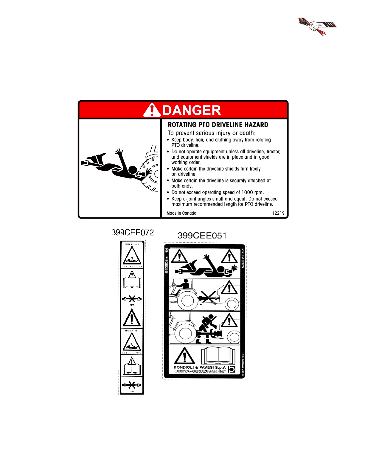
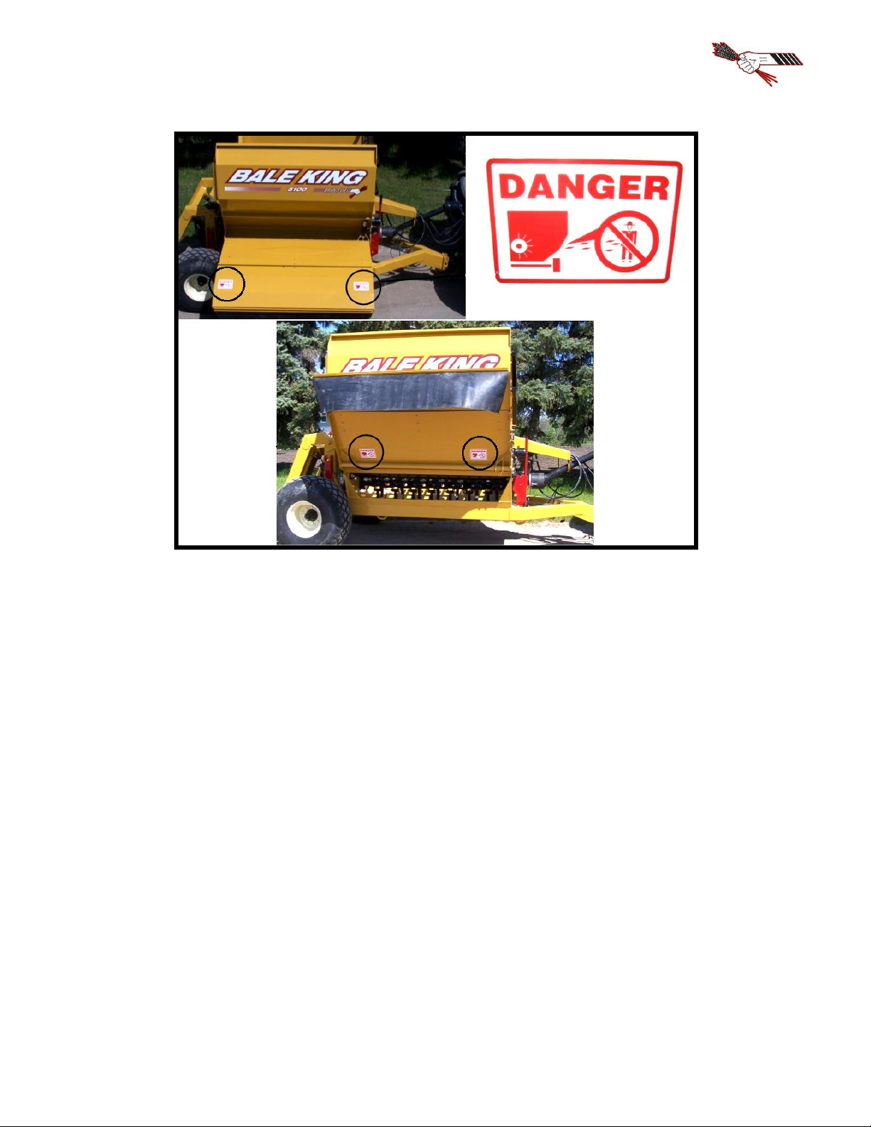
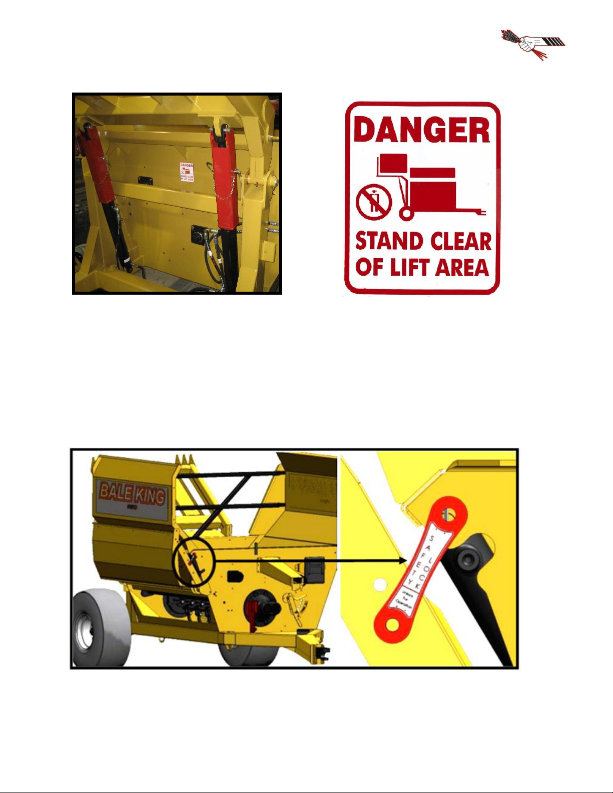
Safety Decals ...................................................................................................................2
Transportation..................................................................................................................5
FEATURES & OPERATION .....................................................................................................8
Power Take-off ................................................................................................................8
Hydraulics......................................................................................................................12
Implement Tongue.........................................................................................................15
Rear Forks......................................................................................................................15
Loading Bales ................................................................................................................17
Hoop Grate Adjustment..................................................................................................18
Deflector........................................................................................................................19
Agitators ........................................................................................................................21
Optional Diverter Kit......................................................................................................22
Optional Fine Chop Kit..................................................................................................23
Optional Total Ration Grain Tank (5300TR)..................................................................24
Optional 3 Bale Kit (5300X) ..........................................................................................25
Optional Back-up Camera ..............................................................................................29
SERVICE AND MAINTENANCE...........................................................................................30
Greasing Locations.........................................................................................................30
Tires...............................................................................................................................33
Twine Removal..............................................................................................................34
Gearbox and Flail Replacement Procedure .....................................................................35
Trouble-shooting Guide..................................................................................................36
Features and Specifications ............................................................................................37
PARTS MANUAL....................................................................................................................38
Machine Overview.........................................................................................................38
Jack & Hitch ..................................................................................................................39
Wheels & Hub................................................................................................................40
Spindle...........................................................................................................................41
Rotor & Drive Components............................................................................................42
Gearbox .........................................................................................................................43
PTO Shaft ......................................................................................................................45
Grates.............................................................................................................................46
Agitators ........................................................................................................................47
Rear Tub Components....................................................................................................48
Rear Deflector / Lights ........................................................................................48
Wing and Bale Slide............................................................................................49
Front Rack .....................................................................................................................50
Rear Forks......................................................................................................................52
Deflector & Hose Cover.................................................................................................53
Front Tub Components...................................................................................................57
Hose Holder and Manual Holder ....................................................................................58
Hose Clamps..................................................................................................................59

Page iv
Slow Moving Vehicle (SMV) Sign Kit...........................................................................61
Decals............................................................................................................................62
Three Bale Kit Option....................................................................................................64
Three Bale Kit Left Arm (Series 1)......................................................................65
Three Bale Kit Lockout Mechanism (Series 1) ....................................................67
Three Bale Kit Center (Series 1)..........................................................................69
Three Bale Kit Right Arm (Series 1)....................................................................70
Three Bale Kit Left Arm (Series 2)......................................................................71
Three Bale Kit Center (Series 2)..........................................................................72
Three Bale Kit Right Arm (Series 2)....................................................................73
Total Ration Grain Tank Option.....................................................................................75
Total Ration Tank Front ......................................................................................76
Total Ration Tank Rear .......................................................................................78
Total Ration Cross Auger....................................................................................80
Total Ration Tank Lid .........................................................................................82
Fine Chop Option...........................................................................................................83
Twine Cutter Option.......................................................................................................85
Back-up Camera Option.................................................................................................86
HYDRAULIC AND ELECTRICAL SCHEMATICS................................................................87
Hydraulic Schematics.....................................................................................................88
Diverter Control Box....................................................................................................105
Lights & Harness .........................................................................................................109
NOTES...................................................................................................................................110

Page 1
INTRODUCTION
Thank you for purchasing a Bale King bale processor. With the proper operation and service as
outlined in this manual, the Bale King will provide you with years of trouble-free operation.
This is a complete safety, operation and parts manual for the Bale King 5300. The manual
covers in detail how to safely and effectively use your new processor. The procedures outlined in
this manual should be followed to ensure safe operation and longevity of your machine. The parts
manual covers all parts you may need to order in case of accident or breakdown. Please read
completely through this manual before beginning operation of your new machine.
Safety Precautions
The following safety precautions MUST be followed to ensure safe operation of the Bale King
bale processor.
•ALWAYS turn OFF the tractor when leaving the operating platform.
•DO NOT stand in front of the discharge chute while the machine is running.
•DO NOT walk or move under the bale forks when they are in the upward position, unless
the cylinder safety lock is in place.
•DO NOT enter the machine while in operation.
•DO NOT clean machine while in operation.
•DO NOT stick any device into the machine to clear debris while the machine is in
operation.
•ALWAYS turn off the machine when cleaning the machine, removing twine, or
hooking/unhooking the machine
•ALWAYS use safety chain when towing the machine on a highway.
•DO NOT operate if any part of the PTO safety shielding is missing or is not secured.

Page 2
Safety Decals
Power Take-off
The operator must obey all safety labels and must maintain the propershielding. Ahigh percentage
of drive-line injuries occur when safety shielding is missing or not functioning properly.
DANGER: Contact with a rotating drive-line can cause serious injury or death.

Page 3
Discharge
DANGER: Do not stand on the discharge side of the machine while it is in operation.

Page 4
Rear Fork Lift Area
DANGER: Stand clear of lift area. Do not stand under the forks unless safety locks are
installed.
Deflector Safety Lock: Unlock for Operation, Lock for Transport and Storage.

Page 5
Transportation
The Bale King 5300 can be safely towed on public roads, provided the following precautions are
met:
Weights and Dimensions
•The towing vehicle must be suitable for the weight being towed.
•Check with local authorities regarding transport on public roads. Follow all applicable
laws and regulations.
•Be aware of your size and weight. Adjust your driving accordingly
Empty
Loaded
5300
5300X 1
5300TR 2
5300
5300X 1
5300TR 2
Total Weight
4400 lb
5070 lb
5200 lb
8000 lb
10 500 lb
10 750 lb
Hitch Weight
1250 lb
1320 lb
1540 lb
2000 lb
1600 lb
2200 lb
Length
19’-8”
19’-8”
19’-8”
20’-10”
20’-10”
20’-10”
Width 3
9’-9”
9’-9”
10’-7”
9’-9”
9’-9”
10’-7”
Height
8’-7”
8’-7”
8’-7”
11’-0”
11’-8”
11’-0”
NOTE 1. The 5300X features the optional 3-bale kit
NOTE 2. The 5300TR features the optional Total Ration grain tank
NOTE 3. Width can be reduced to 8’-6” by folding the deflector
Speed
•The processor features implement tires and hubs and is not suitable for high speed travel
•The processor does not have brakes.
•Slow down for rough conditions, turns, and steep declines.
•If towing long distances, ensure the machine is empty (no bales in tub or on fork)
•If hauling one bale only, place it in the tub instead of on the fork.
•If hauling two or more bales, speed should be further reduced. Note that there will be a
significant amount of weight behind the processor axle, causing more “tail whip”. This
also raises the center of weight of the machine.
•Failure to heed these warning may result in loss of control or death.
Tow Vehicle Weight
Empty Processor
Loaded Processor
10000 lb and Under
32 km/h (20 mph)
Not recommended
Over 10000 lb
40 km/h (25 mph)
32 km/h (20 mph)

Page 6
Safety Chain, Jack, PTO, and Hydraulics
•ALWAYS ensure that the safety chain is properly installed. There should be enough
slack to allow for turning, but not so much that the chain drags on the ground.
•Ensure that the jack is installed in its storage position on the front tub wall.
•Ensure that the PTO and hydraulic hoses are properly secured
•PTO and hydraulic lines must be connected to the tractor during transport.
•If towing with a pickup, the outer PTO shaft must be removed, and the inner shaft and
hydraulic hoses properly secured. The exposed end of the inner PTO shaft should be
covered to protect the splines from dust/rocks, etc.
Wheels and Tires
•Check tire pressure and wheel torque. Wheels must be retorqued after 1 hr if being
transported for the first time.
Tire Pressure
24 psi
Wheel Torque
125 ft-lb
•If transporting long distances, periodically check the tires and hubs for high temperatures.
If heating up, you must slow down.
Lights and Marking
•Tow vehicle must have a 7-pin round trailer plug
•Plug in lights and check for proper function and visibility (flashing amber lights, red tail
lights and brake lights).
•If towing with a pickup, an adapter will be required to plug into the trailer plug. When
braking, both amber lights should activate. Tail lights should always be on.
•Ensure that the supplied SMV (Slow Moving Vehicle) sign is clearly visible from the rear
•Ensure that the reflective markers are cleaned, and visible from all sides

Page 7
Safety Locks
•Lift the forks all the way up. If carrying a bale, only lift enough for appropriate ground
clearance. If empty, install both fork cylinder locks as shown.
•If applicable, the 3-bale clamp should be closed.
•If possible, the deflector should be in the folded position.
•Ensure that the deflector safety lock is installed

Bridgeview Manufacturing Inc.
Page 8
FEATURES & OPERATION
Power Take-off
The Bale King bale processor has a PTO shaft which is splined on both ends. The implement end
uses a 1-3/4"-20 spline with wedge lock bolts. Install onto the gearbox and tighten the wedge
bolts. The bolts should be torqued to 160 ft-lb and re-torqued after 8 hrs of use.
The tractor end comesstandard with a 1-3/8"-21 spline quick detach constant velocity joint.
An optional 1-3/4"-20 spline yoke is available through your Bale King dealer.
The Bale King processor is designed to use a minimum of 100 HP. The drive shaft is
shear-bolt protected. The machine must be operated at 1000 PTO RPM.
NOTE: Spread yokes and twisted drive shafts are signs of OVERLOAD, not a manufacturer’s
defect and therefore not covered by warranty.
•DO NOT operate the machine using a spline adaptor. Use of adaptors will void warranty
due to damage caused to the tractor PTO, PTO driveshaft, or implement.
•DO NOT operate at 540 rpm, or use any kind of adaptor to connect to a 540 rpm spline.
•ALWAYS ensure that the PTOshaft is attached securely to the tractor. Whenthe processor
is not hooked to the tractor, store the shaft on the PTO holder.
•DO NOT transport the processor without securing the PTO shaft. See next page for
securing instruction.
•ALWAYS ensure that the drawbar is adjusted to 16” from the end of the tractor PTO shaft
to the center of the hole in the drawbar.
Operation
To engage the rotor for processing a bale, be sure the PTO shaft is properly connected to the tractor.
Engage the PTO at idle. After the PTO is fully engaged, increase PTO speed until it reaches 1000
RPM.
The processor must not run at any speed less than 1000 PTO RPM as it may result in the
flails springing back against the rotor after they come in contact with the bale. This “backslap”
may cause flails to fatigue and excessive vibration which may cause the bearings to fail. Bales
may be dumped into the tub while the rotor is stopped or while it is running.

Bridgeview Manufacturing Inc.
Page 9
Shear Bolt
All new Bale King processors are equipped with a shear bolt clutch located at the implement end
of the PTO shaft. The correct size shear bolt is 3/8 x 2” Fine Thread Grade 5 with Stover Lock
Nut. Any other size or grade will damage the shear assembly. Spare shear bolts are shipped with
each new machine and are stored along the front top lip of the tub.
If your shear bolt is shearing excessively you may be over-loading the machine. If this
occurs raise the grate assembly to make the machine less aggressive, or roll the bale more slowly.
Always ensure that your machine is running at 1000 PTO RPM.
NOTE: Please consult your local dealer to help pinpoint any problems.
PTO Holder
A PTO shaft holder is standard with your
new Bale King, for safe storage of the
PTO shaft when the processor is not in
use.
When unhooking the PTO shaft
from the tractor, lift the PTO holder to its
upright position and rest the PTO in the
holder. Do NOT transport the machine with the PTO in the holder, slide the outer PTO shaft out
and secure elsewhere. When transporting, fasten the inner PTO shaft to the machine and cover the
open splined end.
The hydraulic hoses may need to be adjusted to best fit your tractor, to avoid damage
from rubbing on the PTO shaft shield. This can be done by loosening the bolt on top of the
plastic hose clamp, then pushing or pulling on the hoses to adjust the length.

Bridgeview Manufacturing Inc.
Page 10
PTO Use and Maintenance
Shut OFF the tractor engine and remove the key before doing any maintenance on the machine.
Use ONLY genuine Weasler parts when replacing any worn or damaged PTO components.
Length:
Confirm the minimum and maximum working lengths of the drive-line.
The telescoping tubes must overlap at least 1/3 of their length when in
use. The PTO is designed to be used with a drawbar length of 16" from
the end of the PTO shaft. Adjust your tractor accordingly.
Shielding:
Be sure that the shielding is not damaged and rotates
freely on the drive shaft.
Working Angles:
Constant Velocity joints can operate up to 80 degrees for short
periods of time. Do not operate for long periods on sharp angles.
Attachment:
Be sure the drive-line is properly attached and all bolts and screws are
tight on the implement input shaft and on the tractor PTO shaft.
Storage:
When not in use, cover or protect the drive shaft from the weather.
When removed from the machine store both halves together to prevent damage. Check all
components for proper function and lubrication before use.

Bridgeview Manufacturing Inc.
Page 11
BEFORE ATTEMPTING ANY REPAIR PROCEDURES,
ALWAYS USE APPROPRIATE EQUIPMENT SUCH AS
SAFETY GLASSES, SAFETY SHOES, AND GLOVES
Shield Removal:
•To remove the shield, pop out the red snap, then rotate
the guard on the bearing to line up the three tabs with
the openings and pull it off away from the knuckle joint.
•Remove the nylon bearing from the shaft by spreading
it open.
Shield Assembly:
•Be sure to lubricate the groove in the inner yokes where the shield
bearing rides. Reinstall shields in the reverse order that they were
removed.

Bridgeview Manufacturing Inc.
Page 12
Hydraulics
WARNING: Pressurized hydraulic fluid can
cause serious injury.
•When working with hydraulicequipment,
eye and hand protection should be worn.
•Do not test for leaks with bare hands.
•Relieve any pressure before removing a
hose or fitting.
•Never work under components raised by hydraulic equipment unless supported externally.
There are three sets of hydraulic hoses to connect to the tractor. Each hose has a coloured marker
to identify its function. They should be connected at best convenience for the tractor's controls.
Note that the hoses are paired by colour and the following tables show the operation when pushing
oil into the hose with the longer marker.
5300 –3 Remote
Long Red
Agitators rotate clockwise
Long Blue
Lift rear fork
Long Yellow
Lift deflector
An optional diverter kit (BMI # 25091) is available to allow the Bale King 5300 to run
using only two sets of hoses. The function is then determined by a control box, mounted in the
cab of the tractor.
5300 –2 Remote
Control Box
“FORK”
“DEFLECTOR”
Long Red
Agitators rotate clockwise
Long Blue
Lift rear fork
Lift deflector
Always set the tractor's hydraulic flow at a lower rate and
adjust it upward untilthe desired speed is reached. Excessive oil flow
may damage the flow divider cartridge.

Bridgeview Manufacturing Inc.
Page 13
An optional 3-bale kit is available to allow the Bale King 5300 to carry an extra bale on
the rear of the machine (see page 25). If this kit is installed, an additional clamp is added to the
hydraulic functions. This changes the hydraulic setup as shown in the following table.
5300X –2 Remote
Control Box
“AUXILIARY”
“FORK”
“DEFLECTOR”
Long Blue
Clamp bale
Lift rear fork
Lift deflector
Long Red
Agitators rotate clockwise
5300X –3 Remote
Control Box
“FORK”
“DEFLECTOR”
Long Blue
Lift rear fork
Lift deflector
Long Red
Agitators rotate clockwise
Long Green
Clamp bale
5300X –4 Remote
Long Blue
Lift rear fork
Long Red
Agitators rotate clockwise
Long Yellow
Lift deflector
Long Green
Clamp bale
An optional grain tank kit is available to allow the Bale King 5300 to carry 40 bushels of grain on
the side of the machine (see page 24). If this kit is installed, additional motors are added to the
hydraulic functions. This changes the hydraulic setup as shown below:
5300TR –2 Remote
Control Box
“AUXILIARY”
“FORK”
“DEFLECTOR”
Long Blue
Discharge grain
Lift rear fork
Lift deflector
Long Red
Agitators rotate clockwise
5300TR –3 Remote
Control Box
“FORK”
“DEFLECTOR”
Long Blue
Lift rear fork
Lift deflector
Long Red
Agitators rotate clockwise
Long Green
Discharge grain
5300TR –4 Remote
Long Blue
Lift rear fork
Long Red
Agitators rotate clockwise
Long Yellow
Lift deflector
Long Green
Discharge grain

Bridgeview Manufacturing Inc.
Page 14
If both kits are installed on the machine, the hydraulic setup is as shown below:
5300XTR –2 Remote
Control Box
“GRAIN TANK”
“AUXILIARY”
“FORK”
“DEFLECTOR”
Long Blue
Discharge grain
Clamp bale
Lift rear fork
Lift deflector
Long Red
Agitators rotate clockwise
5300XTR –3 Remote
Control Box
“AUXILIARY”
“FORK”
“DEFLECTOR”
Long Blue
Clamp bale
Lift rear fork
Lift deflector
Long Red
Agitators rotate clockwise
Long Green
Discharge grain
5300XTR –4 Remote
Control Box
“FORK”
“DEFLECTOR”
Long Blue
Lift rear fork
Lift deflector
Long Red
Agitators rotate clockwise
Long Yellow
Clamp bale
Long Green
Discharge grain
2 Option –2 Remote Control Box

Bridgeview Manufacturing Inc.
Page 15
Implement Tongue
The adjustable hitch on the Bale King features a cast single tongue with hammer strap insert. This
allows for use with tractors equipped with a hammer strap or with a single drawbar. It also allows
the machine to move independently over rough terrain without bending the draw pin.
•Make sure that the drawbar is set to 16 inches behind the PTO shaft for proper PTO length.
•Adjust the hitch height to reduce the PTO angle as much as possible.
•DO NOT install the insert if using a tractor with a hammer strap as this will bend the hitch
pin.
•ALWAYS connect the safety chain during road transport
Rear Forks
The rear fork bale tines can be adjusted side
to side by removing the pin connecting the tine to
the machine and replacing the tine in the other
available gap. Always use tines in the same
position on either side to keep the load on the forks
and cylinders balanced. The widest position is
recommended for all situations, except for the
smallest bales. Always use tines in the same
position on either side to keep the load on the forks
and cylinders balanced.
Drawbar Height
Holes
17.5”
1 & 3
16”
2 & 4
14.5”
3 & 5
13”
4 & 6

Bridgeview Manufacturing Inc.
Page 16
For transport, and safety when working under the forks,
install the red safety locks onto the lift cylinder. The Bale King
5300 is equipped with self-catching safety locks that do not
require a pin to lock in place. To install, lift the fork all the way
up with the hydraulics, place the pin catch of the cylinder lock
against the top pin, and swing into place, resting the base of the
lock on the face of the cylinder chamber.
Other manuals for BALE KING 5300 Series
1
Table of contents
Other Bridgeview Farm Equipment manuals

Bridgeview
Bridgeview BALE KING BRX850 Programming manual

Bridgeview
Bridgeview BALE KING VR581 Programming manual

Bridgeview
Bridgeview FLEXCART 48 User manual

Bridgeview
Bridgeview BALE KING V-MAX 1214 Product manual

Bridgeview
Bridgeview BALE KING 8200 Programming manual

Bridgeview
Bridgeview BALE KING 8300 User manual

Bridgeview
Bridgeview Bale King 6100 Programming manual

Bridgeview
Bridgeview BALE KING 5300 Series Programming manual

Bridgeview
Bridgeview BALE KING 7400 User manual

Bridgeview
Bridgeview BALE KING 5100 Programming manual