Northwest Bear 80-200 User manual

TeamBear USA
Sales 866-0WN-BEAR (696-1317)
Service 877-FIX-BEAR (349-1317)
www.TeamBearUSA.com
,
80.200
.Wheel 13alancer
1620-89593. ~ 1/a~
-====.
'- e:::==a
Team Bear USA
a division of Northwest Equipment Mfg., Inc.
122 East Reserve Drive, Kalispell, MT 59901
406-755-0805, 866-696-2327, 877-349-2327
www.TeamBearUSA.com

BEAR.
80-200 MICROPROCESSORWHEEL BALANCER
..
L
FEATURE /IJ:N1.NrlGE BENEEJT
Autanatic self-cal1bra't1a1 Eliminates Manual No Expens:Lw service
c.l1 w-at1a'1 Ca.1.1a for QI] 1Qr'aticn
'.,
Id.
Zero sPaft Cal1braticn El1minates Need To Zero
.Balance Shaft: By Setv:Lce
TeduU.c:Lan
Autanatic Dit:Lcs No TroubleshoatinO tgw SeJ:v:LQIt0C8t
Requ:Lred
\J Faster Mountinc;l a.nd Saves TinII
Quick C11eckintJSystem DsrguntinQ
Fail-safe Motor If Meter Fa:Lls, S.izI1j)ly IXJwn'r1m8 Avo:Lded
Spin By Hand
Autanatic tkXxi Start Option Allows Operator To start Saves T1.me
.../ Machine By Either Press:LnQ -/
Start .Butta1 or
liJod
Break Nay Shaft Allows Centerless Wheels Mxe Opportua:Lt:Les
To Be Balanced For Profit.
Fine BaJ.ance Rout.ir1e AlCM For Balance BelCM Please Particular CUat:a'nlrs
1/4 oz. CUt Off
Interlock TireShield Prevent Operation Without Safe 0peA.t1an
Tire Shield In Place
'lbree Plug In Service Easy To Serv10e U::Jw
Service Co8t8
MXiules
Self-center Universa! Allc:w Balanc:i.nq of Mao No Need To Turn Nrf
.1C1apter. Ar¥i Centerless Wheels CUstanIIrs II4y
'1bree Dif::erent Balance Allows Operator To CbJoee Ability 'lb Balance
Routines -AutO, Maq 1, The Proper Type Of Balance Spec:1al Whee.V1':Lre
Mag 2 Catbinatiaw

CONTENTS
SPECIFICATIONS 4
CAUTIONINFORMATION 5
"
BALANCINGPROCEOURI!: :: 6
CALIBRATIONPROCEDURE .15
SPECIAL PROBLEMS .17
SPECIAL FUNCTIONS .18
TROUBLESHOOTINGCHART 20
Page 3
I
'-

SPECIFICATIONS
*VOLTAGEAVAILABILITY:
115 VOLTS
*AMPERAGEREQUIREMENTS:
10 AMPS
*RANGEOFWHEELCAPACITIES:
RIM DIAMETER
-10 INCHESTHROUGH18 INCHES
TIRE WIDTH-2 INCHESTHROUGH18 INCHES
MAXIMUMTIRE DIAMETER
-42 INCHES
*REQUIREDWORKSPACEAROUNDBALANCER(WITHHOOD):
LENGTH-46 INCHES
DEPTH-46 INCHES
HEIGHT-49 INCHES
*1/6 H.P. MOTOR,MODIFIEDTORQUE,FORCEDAIR COOLING
.,'.
*BALANCINGCAPABILITY:
DYNAMIC/STATIC -TWOPLANE
*CYCLETIME:
/'
5.9 SECONDS(APPROX.) FORAVERAGEWHEEL
*BALANCINGSPEED:
APPROXIMATELY220 RPM(for average size tire)
*ACCURACY:
START(NORMAL)MODEtl/4 OZ. (ORt3 GRAMS)LINEARTO 19.9 OZ.
STANDARDPACKAGE:
Includes balancer with built-in 18 bin weight tray, interlocked guard hood,
passenger back-cone mounting system, 4 accessory pegs, instruction manual,
and calipers.
Page 4

CAUTIONINFORMATION
A,'.
Wherever this symbol appears, there will be important
instructions for your safe operation of the balancer.
SAFETY'
* Be sure the balancer power cord is connected to a properly grounded outlet
of the correct voltage and ampere rating_
* Do not touch any of the internal electrical circuits of the balancer while
the power cord is connected to the building outlet.
* Do not expose the balancer to rain or moisture, or operate it on a wet
floor.
* Keep hands, hair, and loose clothing away from the spinning parts of the
balancer.
NOT E:
* Use HANDSONLY on keyboards, wheel nut, and adapter.. The use of tools,
hammers, or air tools will void warranty.
Page 5

..
BALANCINGPROCEDURE
SELECTINGTHE WHEELMOUNTINGSYSTEM
BACK-CONESYSTEM
To balance wheels which use the large center hole to locate the wheelan the
vehicle hub, use back-cone mounting whenever possible.
Parts used in the back-cone mounting system are two. cones, one spri ng, a
reversible front cup, and a wheel nut.
BACK-CONEMOUNTINGPROCEDURE
1. Place the spring, large end first, over PRSS£NG£R
the balancer shaft. H
~
H££L ~~S
8RLRNC£R
SHRF T~
41 ez Q-/
~SPRING
8RCKING PLRT£
2. Select a cone to fit the back side of
the wheel. Slide the cone, 1arge end
first, onto the shaft.
3. Snap the black front cup onto the wheel
nut, with large or small end toward the
wheel depending on wheel design.
4. Mount
wheel
5. Thread the wheel nut onto the balancer
shaft. Tighten the wheel nut to be sure
of secure mounting, at least four turns.
NOTE: If wheels with extended centers cover balance shaft threads, use the
SMALL
end of the wheel nut, and do not use the front cup. Again, tighten the
nut at least four turns.
AWheel nut must engage threads for at least four full turns.
Fai 1ure to tighten wheel nut securely or t a force wheel
firmly against ~he faceplate may result in serious personal
injury. .
Page 6

BALANCINGPROCEDURE
SELECTING THE WHEELMOUNTINGSYSTEM .Continued
FRONTCONESYSTEM
Mount 1ight-truck wheels using the 1ight truck front cone. After-market
light-truck wheels with large center holes can be mounted using either the
light-truck cone adapter or the optional combination adapter.
The back cones can be used as front cones if the tire is mounted true and
shows no apparent runout. ''.
*USETRUCKCONEFROMFRONTONLY.
*USEOPTIONALTRUCKSPACERWITHWHEELSHAVINGA CENTERHOLE5" ORLARGER.
AWheel nut must engage threads for at 1east four full
turns. Failure to tighten wheel nut securely or to force
wheel firmly against the faceplate .may result 'In serious
personal injury.
,-*
TRUCKHHEEL NUT
CONE
COMBINATIONADAPTER(OPTIONAL)
Wheels that are true to 1ug patterns must
be mounted using optional combination
adapter. Examples include wheels from 1968
and earlier Volkswagen, Peugeot, and
similar automobiles. Wheels with no center
ho1es are mounted after the threaded
balancer shaft stud is removed.
NOTE: To mountspecialty wheels with "Uni-
Lug," "K-Lug," or slotted-hole mountings,
an adapter from the wheel kit, the 1arge
side of the 1ug nuts, or a combinat ion of
fittings must be used. Check wheel runout
to ensure correct mounting.
Page '7

BALANCINGPROCEDURE
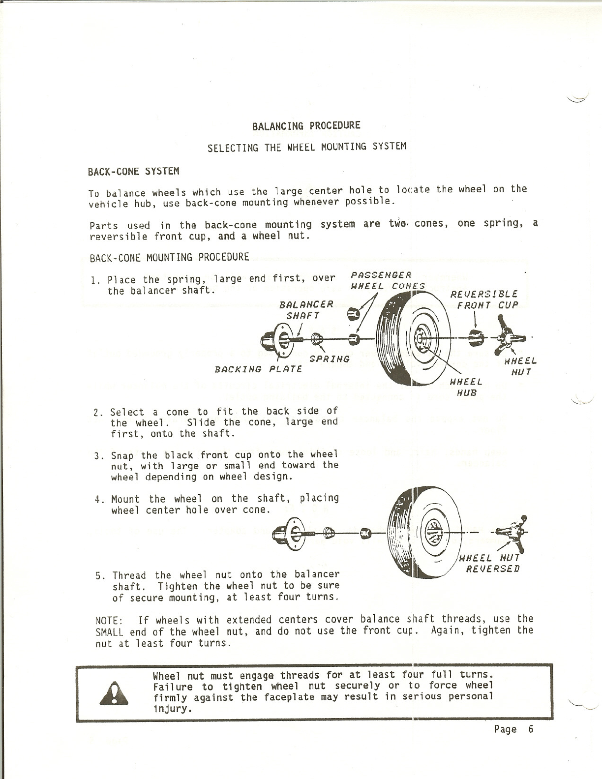
SELECTINGTHE WHEELMOUNTINGSYSTEM Contirued
COMBINATIONADAPTER(OPTIONAL)
Combination adapters can be set up to mount wheels with patterns of three, four,
or five lugs. The three- and four-lug adapters are also used to mount wheels
with six and eight lugs, respectively.
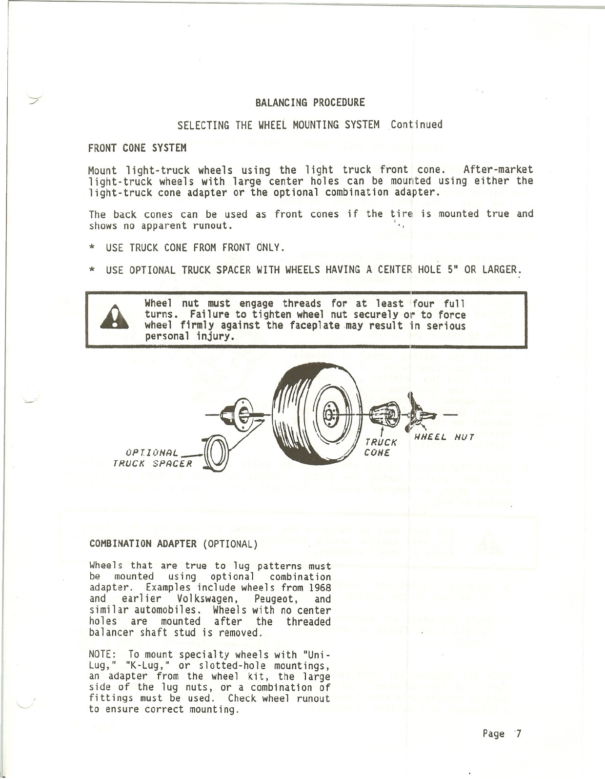
SETTING COMBINATIONADAPTERS
1. With the swivels removed, align Marks
~3, 4, and 5 on the center gear with
like markings on the adapter plate.
2. Install a swivel with the index mark
aligned with Marks 3, 4, and 5 on the
gear. Install but do not tighten
bolts to retain the swivel.
""
~LUG
~SHIVEL
IND£X
MRRK
3. Install the desired number of swivels
in corresponding holes. For example,
if a five-lug adapter is needed,
install the four remaining swivels in
holes marked S. Ensure that the marks
on the swive1s a1ign w.ith the proper
numbers on the center gear. Bolt the
swivels to the adapter but do not
tighten the bolts.
4. Attach the adapter to the wheel. If the bolts are so tight that the swivels
will not rotate, loosen the bolts. Thread lug nuts by hand and tighten
evenly using an adapter wrench. For best results, use a crisscross tigh-
tening method.
81
ALug nuts must be centered and threaded at least four full turns.
Use only adapter wrench furnished with adapter. Do not use air
tools or impact wrenches.
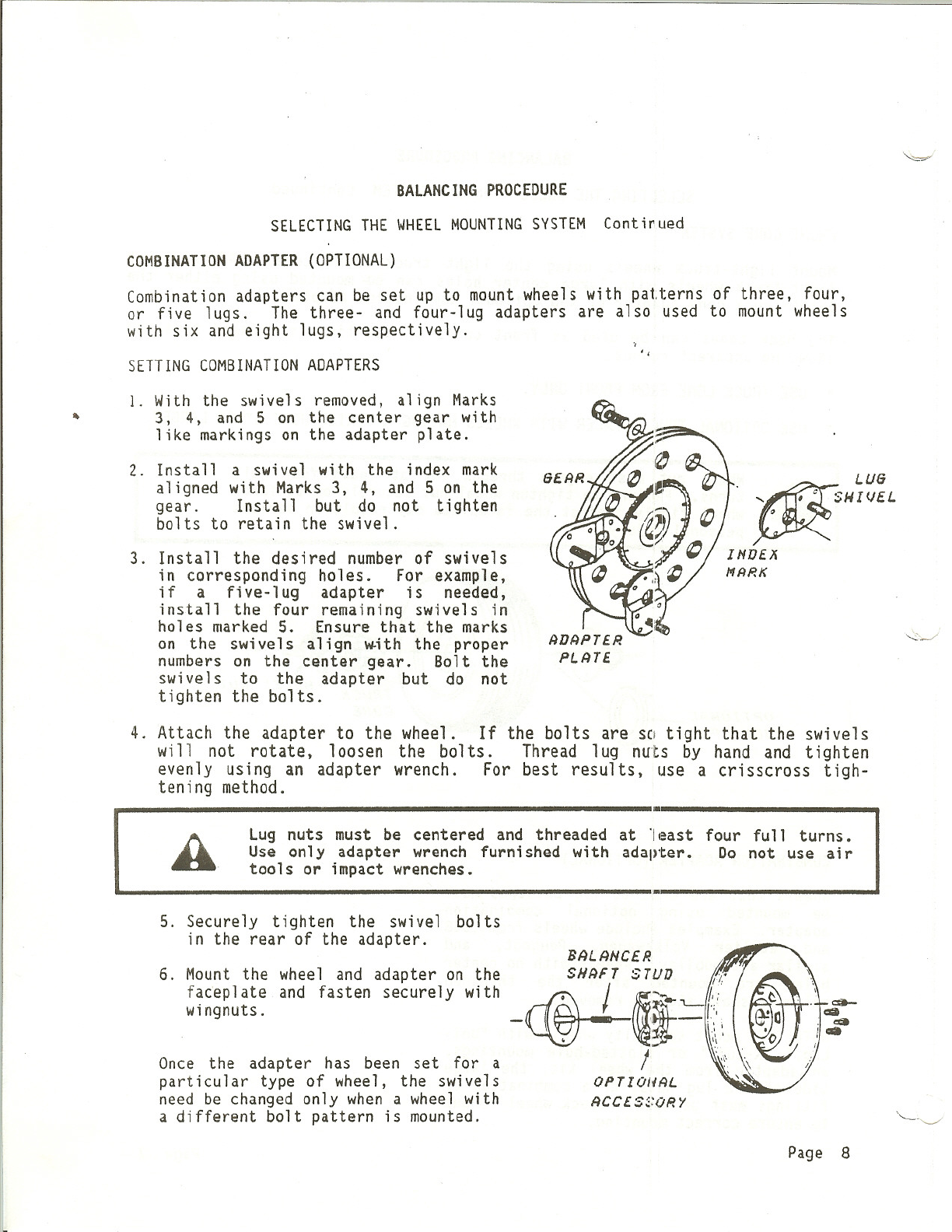
5. Securely tighten the swivel bolts
in the rear of the adapter. B~LRNC£R
6. Mount the wheel and adapter on the SHRFT STUD
~
'l'"
faceplate and fasten securely with c@-L-I
~
~ ~,;
wingnuts. - 'J~r:I.
.
~
' ,
.'
, ,
.~
Once the adapter has been set for a !'
particular type of wheel, the swivels OPTIOH~L
need be changed only when a wheel with ~CC£$~:ORY
a different bolt pattern is mounted.
Page 8

BALANCINGPROCEDURE
CONTROLPANELLAYOUT
,"
NUMBERKEYPAD RIM DISTANCE WHEELWIDTH WHEELDIAMETER.
I
l
Page 9
STAR ITr8n cr£Jc::r [J [!] EJ
STATIC MAG'LU
?...i./.
Ir 0f-:- I;-t-;--t-;
5 I 6I 789

BALANCINGPROCEDURE
GENERAL
*AUTO/MANUAL
Press STOP key to stop wheel rotation at any time while
balancing.
Press AUTO/MANUALkey to change b~tween automatic start
when tire shield is lowered and manual start by pressing
START key.
*STOPKEY
*RESET Pressing the STOP key clears the displays, so you can
start any step back at the beginnin~l.
*MACHINE IS BEST LEFT ON CONTINUOUSLY. If unplugged, allow five minutes
for balancer to warmup. It does not hav~ an on/off switch, and is ready
for operation whenever the power cord is connected to a "1ive" building
outlet.
*Keep faceplate clean and free of burrs, grease and oil.
* The wheel balancing shaft motor does not operate with the tire shield
raised.
* Use back cone system where possible.
* Use truck cone from front only.
*Most accurate 3-1/2 oz. or 100 gram cal ibration is achieved using an
average wheel for your shop and less than 2 oz. (60 grams) imbalance.
* Calibration should be performed only as needed; but always after the
balancer has been repaired.
Page 10
..

'"
BALANCINGPROCEDURE
MEASURINGTHE WHEELAND PROGRAMING
1. RIMDISTANCE
Press (ENTER1), then press number
keys to enter numbers from Rim
Distance Gauge.
ENTER
~
2. WHEELDIAMETER
Press (ENTER2), then press number
keys to enter wheel diameter in
inches.
ENTER
;XI
3. WHEELWIDTH
Press (ENTER3), then press number
keys to enter wheel width shown on
caliper scale.
ENTER
RIM DISTANCE
WI-EEL WIDTH
II
Page 11

BALANCINGPROCEDURE
SELECTINGTYPE OF BALANCE
DYNAMICBALANCINGOF STANDARDSTEEL WHEELSUSING STANDARDCLIP-ON WEIGHTS:
Start spin cycle, as shown on next page.
~
START
~
""
STATICBALANCINGUSINGA SINGLEHIDDENADHESIVEWEIGHTINSIDE RIM:
1
STATIC
!
Press STATIC key once, than start spin cycle,
as shown on next page.
DYNAMICBALANCINGUSING 'ONE ADHESIVE WEIGHT INSIDE, AND ONE ADHE~IVE WEIGHT
AT RIM CENTERLINE:
1~
MAG-ALU
2~
Press MAG-AlU key once, then start spin cycle,
as shown on next page.
DYNAMICBALANCINGUSINGONEADHESIVEWEIGHTONEITHERSIDE OFRIM CENTERLINE:
Press MAG-AlUkey twice, then start spin cycle,
as shown on next page.
1~
MAG.ALU
2~
AWhen using adhesive weights, be sure they l'Ii11 clear disc brake
calipers. .'
Page 12

BALANCINGPROCEDURE
BALANCINGTHE WHEEL
TO STARTWHEELSPIN CYCLE
~
START
~
LOWERSHIELD
PRESSSTARTKEY
'.
AFTERWHEELSTOPSSPINNING
1. Raise tire shield.
AWait until ,wheel stops spinning before raising tire shield.
Failure to do so could result in serious injury.
2. Turn tire by hand until all four arrow lights are lit on either one of the
displays.
INSIDE WEIGHTDISPLAY OUTSIDEWEIGHTDISPLAY
3. Select weight amount shown on that
display. Attach at the top dead
center point of display side of the
rim. Secure cl i p-on weight to rim
edge; secure adhesive weight to
pasit i on desi red when select ing
weight style.
NOTE: If static balancing was
selected, place adhesive weight as
close to center of rim as possible.
Page 13

BALANCING PROCEDURE
BALANCINGTHEWHEELContinued
., "
4. Turn tire by hand until all four arrow lights are lit on other display
(except when STATICbalance is done.)
5. Select weight shown on the display. Attach at the top dead center point
of display side of the rim. Secure clip-on weight ~o rim edge; adhesiVe
weight to position desired when selecting weight style.
CHECKSPIN To check for correct weight placement, pre~s START
(shield down) for another spin cycle.
FINE BALANCE Hold STARTkey in while spin cycle takes place. .
Page 14

CALIBRATION PROCEDURE
After a wheel is balanced, you must run a Check Spi~.(see previous page) to
see that the wheel is balanced accurately. Calibration should be performed
when this check spin reveals that most wheels are not accurately balanced
by the first spin. Calibration also MUSTbe done after the balancer has
been repaired. To discontinue the calibration procedur'e at any time, pr~ss
the stop key. New cal ibration data will not be entered into the machine
until the lOCK key is pressed after "CAl lOCK" flashes, at the end of the
calibration procedure.
The balancer must be plugged in for at least 5 minutes before calibration.
Calibration must be done carefully, as described below. The displays
prompt the next step in the procedure.
(NOTE: Zero cal is no longer required; cycling the balancer without the
weight of a tire and wheel will result in meaningless readings.)
1. Mount an averagf! size tire/wheel (195-14) on the balancer. It is
best that the wheel be balanced, but not necessary. A new straight
rim and tire is best. Press the "3-1/2 oz. cal 100G" key. "ENT1 2
3" will be displayed.
2. Enter the three wheel measurements as directed in the operating
section. lower hood. Press the start key. After- one spin cycle,
"ROT180" will be displayed.
Page 15

CALIBRATION PROCEDURE
3. Loosen hub nut and rotate the wheel 180 degrftes in relation to the
face plate. Do this by holding face plate and noting position of
valve stem and then move. tire until valve stem is opposite the
starting point. Press the start key; "3.5 OUT"will be displayed
after spin cycle.
4. Attach a single 3.5 oz. (or 100 gram) weight ~/here indicated by the
posit ion arrow 1ights on the outer ri m. Pres s the start key; "3.5
IN" will be displayed after spin cycle.
5. Remove the 3.5 weight from outer rim and attach to position
indicated by the arrOw 1ights on the inner r'"im. Press the start
key; "tAL Lot" will be displayed after the spin cycle.
6. Press the Lock key. ~If beeping occurs prior ~o tAL LOC: Make sure
that correct weight and correct wheel were used, and that proper
ca1ibra t ion procedure was used. Pres s the Lock key. and go on to
step 7.)
(7.) If the calibration wheel was out of balance, or if the PCBor Sensor
arm was replaced, perform the following:
Removeall weight from th~ wheel and balance it.
Repeat calibration procedure with the balanced wh~el.
Page 16

SPECIAL PROBLEMS
RETURNS (COMEBACKS)
Possible causes of complaints of vibration after balan~ing are:
"
Tire out of round; wheel out of round, bent, or not true. Balancing
cannot make a tire round. Replace the tire or wheel as necessary.
Stiffness variations in radial belts. The tire should be replaced.
Tire bead improperly seated. Check the bead seating and inflate the tire
to the proper pressure if necessary. Re-balance the wheel.
Suspension wear, misalignment, or worn or loose components.
Whee1 not centered because of damaged hub, damaged or worn center ho1e,.
worn bolt-circle holes, or poor original manufactur'e. Check the wheel
runout before balancing and on the car after mounting. Replace as
necessary.
Sensitive suspensions. Use the fine-balance feature (hold the START
switch depressed during the entire spin cycle).
Sometimes excessive tire lubrication can cause the tire to rotate on the
wheel when the customer drives away. Re-balance the wheel.
Page 17

'.
SPECIAL FUNCTIONS
TEST KEY
Balancer self-tests and displays "End tSt."
display will flash service or error code. If elec~rical problem is found,
"
Automatic Diagnostic Error Codes:
"ERR 3"
Cause
Requires calibration;
batteries. check or replace
OisDlav
"SPO ERR"
Possible optical timer problem.
Po~sible PCB or optical timer problem.
"ROT ERR"
"ERRA" Incorrect rim data enterec.
Beeping prior to
CAL LOC or CAL ERR Possible sensor problem.
If any of the above codes appear, call Service.
Page 18

SPECIAL FUNCTIONS
SPECIAL FUNCTIONCODES
Special function codes allow you to change the normal operation of the
balancer.
To select a special function code:
1. Press the ENTER1 key one time,
,"
2. Press the number nine key three times,
3. Then select one of the three-number codes from this list.
After you select the code the balancer will. operate according to the new
instructions.
CODE WHATDOESIT CHANGE?
000 Places balancer in standard operation (overrides special func-
tions).
001 Displays weights as .01 oz.
010
025
100
Displats weight as .1 oz.
Displays weight as .25 oz. (standard operation).
Displays weight in 1 gram values.
200 Displays weight at 2 gram steps.
500 Displays weight at 5 gram steps.
550 Places balancer in motor drive operation (standard operation).
555 Places balancer in hand spin operation.
604 Disconnects hood interlock. (To reconnect, use Code 000.)
777 Optical timer counter check.
843 Armdata check.
880 Program check number.
Page 19
Table of contents
Other Northwest Wheel Balancer manuals