manuals.online logo
Brands
  1. Home
  2. •
  3. Brands
  4. •
  5. HENNESSY INDUSTRIES
  6. •
  7. Wheel Balancer
  8. •
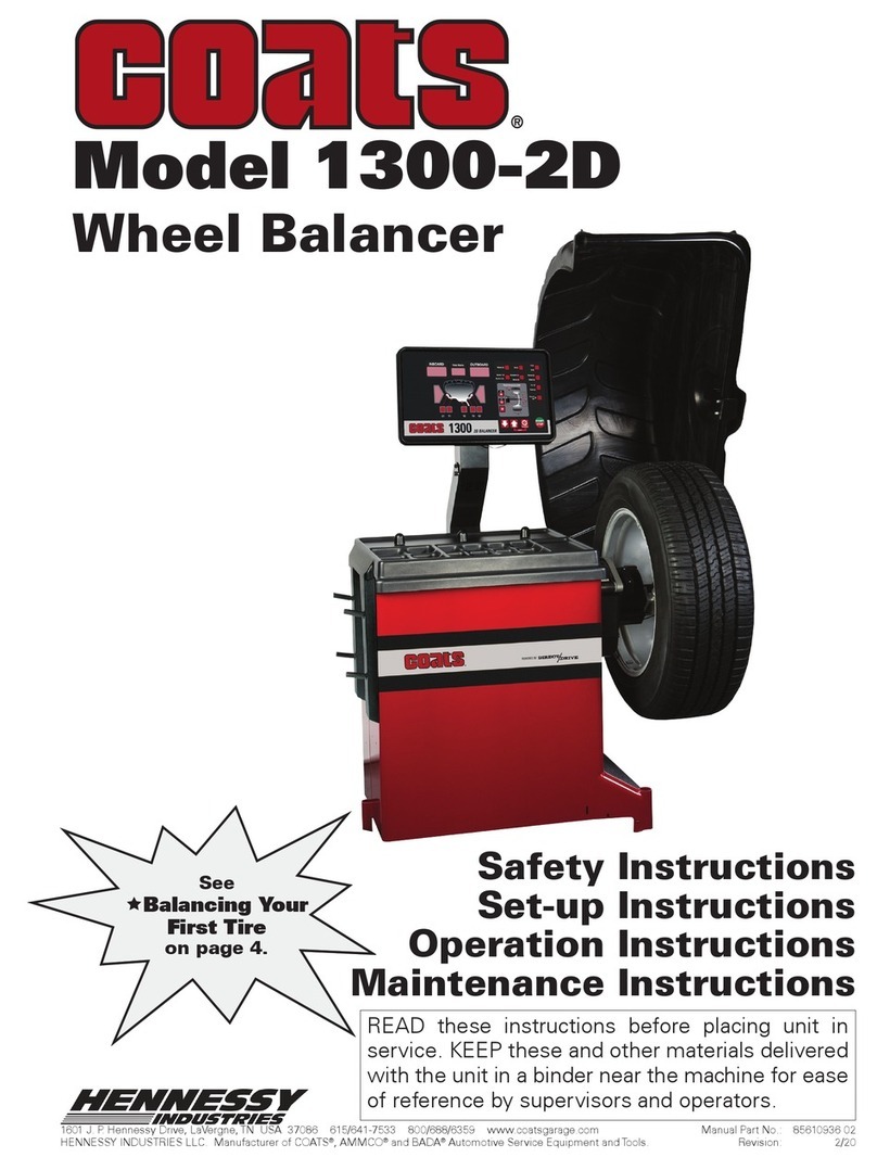
  9. HENNESSY INDUSTRIES coats 1400 2D Use and care manual

HENNESSY INDUSTRIES coats 1400 2D Use and care manual

This manual suits for next models

2

Other HENNESSY INDUSTRIES Wheel Balancer manuals

HENNESSY INDUSTRIES COATS 950 User manual

HENNESSY INDUSTRIES

HENNESSY INDUSTRIES COATS 950 User manual

HENNESSY INDUSTRIES coats 1300-2D User manual

HENNESSY INDUSTRIES

HENNESSY INDUSTRIES coats 1300-2D User manual

HENNESSY INDUSTRIES coats 525 User manual

HENNESSY INDUSTRIES

HENNESSY INDUSTRIES coats 525 User manual

HENNESSY INDUSTRIES Coats 1100 User manual

HENNESSY INDUSTRIES

HENNESSY INDUSTRIES Coats 1100 User manual

HENNESSY INDUSTRIES Coats 1250 User manual

HENNESSY INDUSTRIES

HENNESSY INDUSTRIES Coats 1250 User manual

HENNESSY INDUSTRIES Coats IBS 2000 User manual

HENNESSY INDUSTRIES

HENNESSY INDUSTRIES Coats IBS 2000 User manual

HENNESSY INDUSTRIES coats 1000 User manual

HENNESSY INDUSTRIES

HENNESSY INDUSTRIES coats 1000 User manual

HENNESSY INDUSTRIES Coats Vero Series User manual

HENNESSY INDUSTRIES

HENNESSY INDUSTRIES Coats Vero Series User manual

HENNESSY INDUSTRIES COATS 700 User manual

HENNESSY INDUSTRIES

HENNESSY INDUSTRIES COATS 700 User manual

HENNESSY INDUSTRIES Coats 885 Installation instructions

HENNESSY INDUSTRIES

HENNESSY INDUSTRIES Coats 885 Installation instructions

HENNESSY INDUSTRIES Coats XR 1850 Series User manual

HENNESSY INDUSTRIES

HENNESSY INDUSTRIES Coats XR 1850 Series User manual

HENNESSY INDUSTRIES coats ProRide Diagnostic User manual

HENNESSY INDUSTRIES

HENNESSY INDUSTRIES coats ProRide Diagnostic User manual

HENNESSY INDUSTRIES Coats 1185 User manual

HENNESSY INDUSTRIES

HENNESSY INDUSTRIES Coats 1185 User manual

Popular Wheel Balancer manuals by other brands

Snap-On WBM250 user manual

Snap-On

Snap-On WBM250 user manual

Mondolfo Ferro MT 2450 Technical & service manual

Mondolfo Ferro

Mondolfo Ferro MT 2450 Technical & service manual

IDEAL IWA-60-1500-K manual

IDEAL

IDEAL IWA-60-1500-K manual

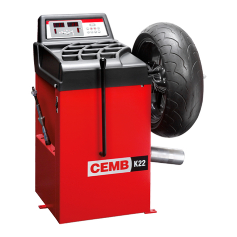
CEMB K22 Use and maintenance manual

CEMB

CEMB K22 Use and maintenance manual

Atlas Equipment WB55 Installation & operation manual

Atlas Equipment

Atlas Equipment WB55 Installation & operation manual

Bonica BC988 Operation manual

Bonica

Bonica BC988 Operation manual

Hofmann geodyna 990-2 Operation manual

Hofmann

Hofmann geodyna 990-2 Operation manual

Hofmann POWER CLAMP features Additional instructions

Hofmann

Hofmann POWER CLAMP features Additional instructions

CLAS EQ 2100 manual

CLAS

CLAS EQ 2100 manual

BOHYUN BY- 6S user manual

BOHYUN

BOHYUN BY- 6S user manual

Urrea BAL24A user manual

Urrea

Urrea BAL24A user manual

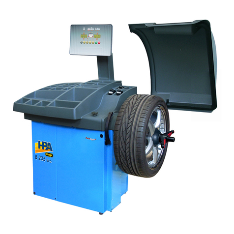
HPA-Faip B 235 Evo Operator's manual

HPA-Faip

HPA-Faip B 235 Evo Operator's manual

Fasep VIDEOTRONIC V788.G3 user manual

Fasep

Fasep VIDEOTRONIC V788.G3 user manual

Hofmann Megaplan Megaspin 800_2 Use and maintenance manual

Hofmann Megaplan

Hofmann Megaplan Megaspin 800_2 Use and maintenance manual

CLAS EQ 3000 manual

CLAS

CLAS EQ 3000 manual

SICE S 605 instruction manual

SICE

SICE S 605 instruction manual

Hofmann geodyna 6800 Operation manual

Hofmann

Hofmann geodyna 6800 Operation manual

Rotary R148 Pro instruction manual

Rotary

Rotary R148 Pro instruction manual

manuals.online logo
manuals.online logoBrands
  • About & Mission
  • Contact us
  • Privacy Policy
  • Terms and Conditions

Copyright 2025 Manuals.Online. All Rights Reserved.

Model 1600 Shown
READ these instructions before placing unit in
service. KEEP these and other materials delivered
with the unit in a binder near the machine for ease
of reference by supervisors and operators.
Calibration Instructions
Wheel Balancer Models
1400 2D, 1500 3D, 1600 3D
Model 1500 ShownModel 1400 Shown
1601 J. P. Hennessy Drive, La Vergne, TN USA 37086 615/641-7533 800/688-6359 www.coatsgarage.com Manual Part No.: 85610675 05
HENNESSY INDUSTRIES LLC Manufacturer of COATS®, AMMCO® and BADA® Automotive Service Equipment and Tools. Revision: 02/20
Important: Always read and follow instructions.
Calibration
Machine Calibration
1. Enter the MACHINE CALIBRATION mode.
2. Enter the D dimension (include decimal point,
example: 16.0 for a 16-inch wheel). Press ENTER.
3. Lower the hood and press SPIN.
4. After spin, raise the hood. Attach 4-ounce calibra-
tion weight to the outside flange at top-dead-center.
Figure 40 - Calibration Weight On Outside Flange At Top-Dead-
Center
5. Lower the hood and press SPIN
Important: It is critical that the inner weight be placed
accurately to achieve proper calibration. If the calibration
weight is not moved from the outside flange directly
across to the inside flange, an inner weight placement
error will occur. To correct, follow the balancer instruc-
tions.
6. After spin, raise the hood. Move the 4-ounce cali-
bration weight directly across and attach it on the inside
flange at top-dead-center (12 o’clock position).
Figure 41 - Calibration Weight Moved (Directly Across) To
Inside Flange
7. Lower the hood and press SPIN.
Note: Rotate laser dot toward inner flange.
8. After spin, raise the hood. Rotate wheel to line up/
center of 4-ounce calibration weight with laser dot. Hold
position while pressing NEXT.
9. Press NEXT; then press EXIT.
Note: On control panel models complete the machine
calibration procedure. Then press and hold the SHIFT
key and press 3 to access the CAL ARM mode.
10. Bring the cone edge of the arm precisely to the
outer edge of the faceplate and hold it there (through
step 12) while pressing the NEXT. (If necessary to reach
the faceplate accurately, loosen the calibration wheel
temporarily.)
11. With arm cone still at the edge of the faceplate,
enter the A dimension (include decimal point) read off
the arm gauge; see figure 41. Press ENTER.
Figure 42 - While Holding Arm Cone at Faceplate Edge,
Enter A
12. Move arm to its home position and press NEXT.
13. Move arm to clip-on weight location on rim
flange and hold it there (through step 16). Wait for volt-
age reading to stabilize, then press NEXT.
14. With arm still at clip-on weight location, enter
the D dimension (16.0 for a 16-inch wheel) that is the
diameter of the tire. Press NEXT.
15. While still holding the arm at the wheel’s clip-on
weight location, enter the A dimension (include decimal
point) read off the arm gauge. Press ENTER
16. Return the arm to home position; calibration is
complete. Press EXIT. Press STOP & EXIT to go back to
the main screen.
Hold Arm
Cone Edge
At Edge Of
Faceplate
Enter A
Value
Shown On
Arm Gauge
Weight
Weight