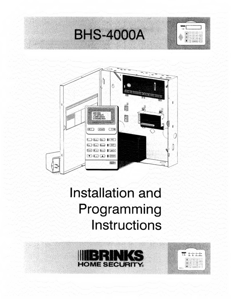
BRINKS BHS 2000A Assembly instructions

%
BHS
2000A
PANEL
TABLE
OF
CONTENTS
1.
INSTALLATION
&
PROGRAMMING
MANUAL
2.
TESTING/UPGRADING/VARIATIONS
FROM
"C"
PANLEL
3.
S
Y
S
TEM
OPERATION
(2000ABND.SAM)
August
15,1994

Table
of
Contents
Introduction
Installation
Alarm
Control
Panel
System
Control
Station
Digital
Communicator
ZIB-8
8-Zone
expander
Electrical
Connections
Hook-up
label
Programming
options
Prism
Keypad
programming
(PGM-670)
Programming
Worksheet
Programming
Trouble
shooting
UL
and
CSFM
Verification
ULC
verification
Specifications

BRINKS
BHS-2000A
ALARM
CONTROL
PANEL
AND
DCU-602B
SYSTEM
CONTROL
STATION
INTRODUCTION
The
BHS-2000A
Burglar
and
Fire
Alarm
Security
System
is
a
microprocessor
based
Alarm
Control
Panel
(ACP)
which
offers
sophisticated
alarm
control,
detection
and
reporting
functions
at
a
price
considerably
less
than
other
panels
with
similar
features.
The
panel
which
is
housed
in
rugged
steel
cabinet,
contains
no
user
indicators
or
switches
therefore
its
installation
location
can
be
chosen
to
make
the
hookup
wiring
more
convenient.
The
BHS-2000A
ACP
contains
8
individually
programmable
zones
of
protection
(detection
loops).
All
zones
use
a
4.7K
ohm
End-of
Line
(EOL)
resistor
for
supervision
unless
otherwise
programmed.
The
8
programmable
zones
can
be
configured
to
function
as
any
one
of
14
different
types
of
detection
circuits
including
fire.
The
BHS
Series
ACP
also
contains
an
integral
32
channel,
multi-format
digital
communicator
that
is
compatible
with
most
major
brand
receivers.
{BHS-2000A
reports
in
SIA
only}.
With
its
extended
data
reporting
capabilities,
it
can
send
more
than
1000
different
alarm
and
status
reports
to
the
Alarm
Monitoring
Center
(AMC).
The
desired
system
configuration,
optional
features
and
other
operation
characteristics
of
both
the
ACP
and
the
digital
communicator
are
programmed
into
a
EEPROM
(Electrically
Erasable
Programmable
Read
Only
Memory).
The
panel
is
shipped
pre-programmed
with
standard
features
which
may
be
changed.
With
an
optional
Programming
Display
Module
(PGM-670).
The
BHS-2000A
may
also
be
programmed
remotely
over
the
telephone
using
PRISM
II
along
with
an
IBM
AT
or
compatible.
Using
PRISM
II
Software
multiple
panel
programs
may
be
programmed
from
Sctatch
or
from
templates
and
either
automatically
or
manually
downloaded
in
a
manner
of
seconds.
The
same
software/modem
combinations
may
be
used
to
bypass
a
swinging
contact,
or
access
Alarm
Memory
information
of
the
last
alarm
events
along
with
present
System
status
or
disconnect
service
to
a
non
paying
client.
The
BHS-2000A
ACP
has
a
built
in
alarm
siren
driver
for
local
alarm
sounding
purposes,
as
well
as
all
of
the
other
optional
features
normally
required
in
a
modem
state-of
the
art-plus
security
system.
3

The
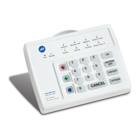
SCS
is
a
surface
mounted
decorative
remote
control
unit
consisting
of
a
12
button
keypad,
3
Emergency
Dispatch
keys,
and
an
easy
to
read
static
LCD
type
display
in
addition
to
an
internal
audio
annunciator
(beeper).
This
remote
control
provides
all
of
the
required
input/output
(unctions
used
in
the
daily
operation
of
the
system.
IMPORTANT
PLEASE
READ
AND
FULLY
UNDERSTAND
THE
BHS-2000A
USERS
MANUAL
BEFORE
PROCEEDING
TO
READ
THIS
MANUAL
OR
ATTEMPTING
TO
INSTALL
THE
SYSTEM.
THE
USERS
MANUAL
DESCRIBES
THE
NUMEROUS
FEATURES
,
FUNCTIONS,
AND
OTHER
USER
INTERFACE
REQUIREMENTS
OF
THE
SYSTEM
IN
GREAT
DETAIL.
THEREFOR,
USERS
MANUAL
INFORMATION
WILL
NOT
BE
REPEATED
IN
THIS
MANUAL.
********jn
STAL
lation*****
**********
MECHANICAL
INSTALLATION
Many
features
have
been
designed
into
the
BHS-2000A
ACP
and
SCS
to
enable
quick
and
simple
system
installation
and
troubleshooting.
The
ACP
contains
no
user
switches
or
indicators
thus
enabling
the
installer
to
select
the
mounting
location
most
convenient
for
wiring.
The
decorative
SCS
may
be
installed
in
a
variety
of
locations
(up
to
4)
to
offer
the
most
convenience
to
the
user.
ALARM
CONTROL
PANEL
(ACP)
The
ACP
should
be
mounted
in
a
convenient,
dry
location
near
a
power
outlet.
We
recommend
the
ACP
not
be
mounted
in
an
attic
or
any
other
similar
location
likely
to
contain
excess
heat.
The
ACP
is
typically
mounted
on
a
wall
using
screws,
toggle
or
Molly
bolts
through
the
holes
provided
in
the
rear
of
the
cabinet.
Using
the
metal
housing
as
a
mounting
template,
mark
and
drill
the
two
top
mounting
screw
holes.
Screw
the
top
screws
partially
in
and
hang
the
hosing
on
the
screws
in
order
to
mark
the
fcxact
location
for
the
lower
mounting
screw
holes.
Wiring
from
the
external
accessories
is
brought
into
the
metal
cabinet
through
one
or
more
of
the
entry
holes
or
knockouts
provided.
To
avoid
possible
confusion,
we
suggest
that
the
different
wires
be
labeled
and
their
polarity
indicated.
This
is
not
only
helpful
during
installation,
but
allow
at
a
latfer
date
if
any
troubleshooting
is
required.
In
order
to
prevent
possible
accidental
damage
to
the
printed
circuit
board,
we
suggest
that
the
board
be
removed
only
if
repairs
are
necessary.
When
removing
or
wiring
with
the
main
printed
circuit
board,
care
should
be
taken
to
first
discharge
any
static
buildup
by
touching
the
metal
hosing
before
handling
the
board.
Handle
the
printed
circuit
board
by
touching
ONLY
the
edges
of
the
board,
heat
sink,
or
terminal
strips.
Battery
leads
are
already
attached
to
the
printed
circuit
have
quick-connect
slide
connectors
for
attachment
to
the
battery.
4

The
ACP
contains
8
different
independently
programmable
zones
of
protection
(detection
loops).
All
zones
are
supervised
with
EOL
resistors.
If
the
Non-EOL
resistor
mode
is
enabled,
no
EOL
resistors
are
required
for
burglary
type
zones
of
protection
but
only
NC
contacts
can
be
used.
Fire
type
zones
of
protection
still
require
EOL
resistors.
Fire
type
zones
cannot
be
programmed
on
Zone
Expander
(ZIB-8)
zones
9-16.
The
status
of
these
zones,
including
alarm
memory,
etc.,
are
displayed
on
static
LCD
screen.
Each
of
these
8(16)
zones
can
be
programmed
into
the
EEPROM
at
installation
to
function
as
any
one
of
the
following
14
different
types
of
detection
circuits.
ZONING
As
described
in
the
Users
Manual,
the
BHS-2000A
protection
zones
can
be
easily
zoned
in
and
out
of
the
security
system
to
provide
for
maximum
versatility
and
convenience.
Any
or
all
of
the
Zones
1
through
8
can
be
programmed
as
Standard
Bypass
(Motion
off)
Zones
in
the
EEPROM.
These
can
be
zoned
in
or
out
as
group
(only
while
the
ACP
is
disarmed)
by
entering
the
correct
key
sequence
on
the
SCS
keypad.
When
these
zones
are
bypassed,
the
SCS
will
indicate
"Motion
off’.
The
user
can
allow
bypass
24
hour
loops
if
they
are
included
in
this
group;
therefor
care
must
be
taken
to
ensure
that
only
the
desired
zones
are
included.
The
Standard
Bypass
is
typically
used
for
shunting
interior
protection
for
at
home
arming.
The
zones
programmed
as
bypass
enabled
zones
can
individually
be
a
zone
in
or
out
(sometimes
referred
to
as
shunted
or
bypassed)
of
the
system
while
the
ACP
is
disarmed.
Reference
Users
manual.
ALERT
ZONES
Any
of
zones
1-8(16)
can
be
programmed
as
Alert
Zones.
The
Alert
Mode
can
be
enabled
and
disabled
from
the
SCS.
This
mode
(sometimes
referred
to
as
Chime
Mode)
allows
the
user
to
audibly
monitor
the
status
of
the
zones
without
Arming
the
system
and
thus
causing
an
alarm.
During
initial
installation
and
programming,
ensure
that
the
loops
most
applicable
to
this
feature
are
assigned
as
alert
(chimes)
zones.
Chime
Zones
are
most
typically
used
for
doors
and
can
be
thought
of
as
a
Daytime
Announcing
System.
ALARM
PANEL
OPTIONS
The
Three
to
four
Digit
Master
Code,
The
E/E
times
and
Fire/Police
Alarm
duration’s
may
all
be
programmed
into
the
EEPROM
at
installation,
and
may
only
be
changed
via
installer
reprogramming
of
the
EEPROM.
Factory
preprogrammed
values
are
provided
for
all
programmable
parameters
to
minimize
installation
programming.
Using
the
Master
Code,
the
user
may
then
program
or
reprogram
up
to
6
Secondary
Arm/Disarm
Codes.
Several
additional
options
including
Power
up
arm,
Quick
arm,
and
Silent
Burglary
are
programmable
at
installation.
AC
power
is
checked
continually
and
DC
power
is
checked
every
15
seconds
by
the
microprocessor
disabling
the
AC
power
momentarily.
5

1
New
BHS-2000A
features
Smoke
detector
reset
feature-
The
Fire
power
is
only
reset
when
the
unit
is
turned
off
after
a
Fire
Alarm
zone
has
been
violated.
If
the
zone
is
still
violated
(shorted),
the
ACP
will
automatically
reset
the
fire
power
30
minutes
later.
If
the
second
attempt
fails,
the
"Call
Brinks"
segment
on
the
keypad
is
lit
and
the
trouble
beep
initiated.
The
panel
will
then
report
a
trouble
to
the
central
station.
Kill
and
resurrect
feature-
(Kill
panel
bit)
-
This
feature
is
used
in
the
event
of
a
non-paying
client.
If
activated,
all
functionality
at
the
panel
is
disabled
except
for
the
local
annunciation
of
a
tripped
fire
zone.
Display
on
the
keypad
will
read
"Not
Ready
&
Call
800...".
Features
such
as
the
ring
count,
Answering
machine
bypass,
and
auto
test
will
remain
functional.
Panel
can
be
resurrected
remotely
(PRISM)
or
by
reprogramming
at
the
site
(PGM-670).
6

SYSTEM
CONTROL
STATION
(SCS)
-C-
H.
IIIIBRINKS
HOW
SKUWlY
ON
QD
53
S
EHI10®
QD
[7]
QD
l*
1
"^
IT]
I
CANCEL
|
|opnoNs|
The
aesthetic
appearance
of
the
SCS
enables
it
to
be
located
in
a
variety
of
locations.
This
will
allow
the
user
maximum
convenience
in
using
the
many
features
of
the
system
and
will
encourage
regular
testing.
The
SCS
is
typically
surface
mounted
at
a
convenient
location.
Remove
the
backplate
by
unsnapping
the
front
housing
using
a
slotted
screwdriver
on
the
bottom
slots
of
the
keypad.
Place
the
backplate
against
the
wall,
making
sure
it
is
level,
then
use
the
appropriate
screws
to
mount
the
unit
securely
to
the
wall.
After
fastening
the
backplate
to
the
wall
and
connecting
the
wires,
clip
the
top
of
the
SCS
over
the
backplate
and
snap
in.
The
dispatch
keys
are
recessed
to
prevent
accidental
depression.
Covers
can
be
used
(provided
by
Brinks)
to
cover
the
dispatch
keys
in
order
to
disable
this
function.
The
SCS
is
supplied
with
a
pull
up
zone
card
window
to
write
down
the
corresponding
area
to
zone
numbers.
The
keys
and
LCD
display
are
backlit
for
convenient
viewing
in
darkness.
The
SCS
requires
only
a
simple
four
wire
connection
to
the
ACP.
Use
ordinary
4
conductor
telephone
cable
for
the
SCS.
Up
to
4
SCS
units
may
be
connected
with
cable
lengths
up
to
a
maximum
distance
of
300
feet.
Any
SCS
cables
longer
than
50
feet
should
be
home
run
back
to
the
ACP.
The
SCS
is
the
users
point
of
system
control.
AH
daily
operation,
programming,
alarm
memory
checks,
and
testing
functions
can
be
performed
directly
form
the
SCS.
The
seven
indicator
lamps
and
the
SCS
internal
annunciator
provide
the
user
with
visual
and
audible
indication
of
the
system
status.
For
further
information
on
user
operation
and
programming
features,
please
refer
to
the
BHS-2000A
Users
Manual.
7

DIGITAL
COMMUNICATOR
CONNECTION
The
BHS
2000A
comes
with
an
8
conductor
phone
plug
which
connects
directly
to
an
RJ31X
phone
jack
(not
supplied).
The
BHS
series
panels
contains
an
integral
32
channel
digital
communicator.
This
dialer
can
report
its
data
to
receivers
at
two
different
telephone
numbers.
Each
telephone
number
can
be
up
to
16
digits
long.
Five
second
pauses
may
be
inserted
into
the
phone
numbers
for
PBX
etc.
compatibility.
Do
not
program
the
phone
number
of
a
police
or
fire
station
unless
assigned
specifically
by
that
agency
and
signal
transmission
has
been
checked
for
compatibility.
The
communicator
will
either
report
the
same
or
a
different
3
or
4
digit
account
code,
as
programmed,
to
each
receiver.
Hexadecimal
(sometimes
referred
to
as
Hex)
digit
may
be
use
either
the
account
code
or
the
reporting
codes.
Each
item
has
a
factory
preprogrammed
code,
any
or
all
of
which
may
be
reprogrammed
at
installation.
Two
of
the
programmable
functions
available
are
Answering
machine
bypass
and
Voice
mail
defeat.
If
an
Answering
Machine
or
FAX
Machine
is
connected
to
the
sathe
lines
4S
the
ACP,
Enablement
of
this
feature
will
cause
the
ACP
to
look
for
the
PRISM
ID
Block
when
the
off
hook.
If
this
ID
block
is
received,
then
the
panel
will
seize
the
line
and
proceed
downloading.
The
Voice
itiail
feature
is
made
to
provide
AMB
for
TelCo
Voice
Mail
services.
With
those
services,
after
a
selected
dumber
of
rings
(usually
2-5
rings),
the
Central
Office
will
steal
the
call
a\Vay
and
place
it
ihto
voice
mail.
If
this
feature
is
left
enabled,
the
panel
will
count
the
number
of
times
the
line
cut
relay
is
triggered.
On
the
fourth
attempt
within
60
seconds,
the
panel
will
seize
the
line
on
the
first
ring.
The
voice
mail
feature
is
used
in
conjunction
with
the
PRISM
downloading
software.
The
dialer
can
be
programmed
to
call
in
automatically
(0-255
days)
and/or
manually.
Manual
testing
is
initiated
by
the
user
and
regardless
of
dialing
attempts
programmed,
Manual
test
message
will
only
attempt
2
call
to
the
Central
station.
Failure
on
the
second
attempt
will
prompt
a
"CP"
communications
problem
and
a
"Call
800..."
on
the
keypad
.
Line
cut
feature
will
trigger
approximately
45
seconds
+-15
seconds.
S1A
format
is
only
available
on
the.BHS-2Q0QA
,
Connection
of
the
fire
alarm
signal
to
a
fire
alarm
headquarters
or
a
central
station
shall
be
permitted
only
with
the
approval
of
the
local
authority
having
jurisdiction.
Burglary
alarm
signals
shall
not
be
connected
to
a
police
emergency
number.
Connection
of
the
fire
alarm
signal
to
a
fire
alarm
headquarters
or
a
central
station
shall
be
permitted
only
with
approval
of
the
local
authority
having
jurisdiction.
RJ3IX
Connection:
Make
sure
polarity
on
Ring
and
TIP
are
connected
for
proper
line
cut
timing.
Terminal
Color
Eunctlpn
1
Blue
Ring
out
(+)
2
Orange
*
3
Black
+
4
Red
Ring
in
(-)
5
Green
Tip
in
(+)
6
Yellow
*
7
Brown
*
8
Gray
Tip
out
(+)
8

ZIP-8
8
ZONE
EXPANDER
SPECIFICATIONS
Size:
3"x4"x
.63"
Power:
I2VDC,
85
mA
Zones:
8
zones.
Specified
as
zones
9-16
Connection:
J4
Notes
on
ZIB-8:
1.
Do
not
use
zones
9-16
for
Fire
Zones.
ZIB
-8
is
not
a
CSFM
listed
accessory
2.
Zones
9-16
are
always
bypassable
and
Standard
or
Special
Bypass
groups
cannot
be
programmed.
3.
Do
not
program
Zones
9-16
as
Nomad,
Nomad
Delay
zones
4.
Subtract
current
draw
of
ZIB-8
from
the
Auxiliary
and
Fire
power
when
calculating
maximum
current
draw.
9

ELECTRICAL
CONNECTIONS
TERMINAL
1
&2
3
4
and
5
5
and
6
5
5,7,12,15,18,21,24
8(+)
9
10
11
13
and
12
Hand
15
16
and
15
(7
and
18
REFER
TQ
THE
HOOK-UP
LABEL
FUNCTION
AND
DESCRIPTION
AC
Input.
Connect
the
input
terminals
to
a
UL
and/or
CSA
listed
Class
2
transformer.
Use
18
AWG
wire
with
a
maximum
length
of
50
feet.
Not
used
Bell
output,
connect
a
bell
or
strobe
to
these
terminals.
This
output
is
limited
to
500
mA
ai
12.5
VDC.
1
amp
for
CSFM.
Siren
output.
4
ohms
max.
connect
a
maximum
of
two
8
ohm
(4
ohms),
10
W
min.
speakers
in
parallel
to
these
terminals.
Use
18
AWG
wire
with
a
maximum
length
of
50
feet.
No
external
siren
driver
is
necessary.
Negative.
Earth
Ground
Common.
All
common
terminals
are
marked
with
a
under
the
number.
Aux
Power.
This
terminal
provides
12.5
VDC.
Maximum
combined
current
of
Aux.
power
and
Fire
(terminal
11)
is
330
mA
using
a
20VA
transformer
and
500
mA
using
a
25
VA
transformer.
May
be
used
with
any
common.
Note:
The
red
wire
from
the
SCS
is
12
VDC
and
must
be
connected
to
terminal
8.
The
black
wire
from
the
SCS
is
common
and
may
be
connected
to
any
common
terminal.
Keyboard
Clock.
This
terminal
provides
the
clock
signal
for
the
SCS
and
is
connected
to
the
green
wire
on
the
SCS.
Up
to
4
SCS's
may
be
connected
in
parallel
with
cable
length
up
to
300
feet.
Using
ordinary
4
conductor
telephone
cable.
Home
run
any
SCS
cables
in
excess
of
50
feet.
IMPORTANT:
Do
not
run
the
SCS
or
any
detection
loop
wires
alongside
(within
4
inches)
of
the
siren,
16VAC
or
110VAC
lines.
Keyboard
Data.
This
terminal
provides
the
data
signal
for
the
SCS
and
should
be
connected
to
the
Yellow
wire
on
the
SCS.
Fire
power.
This
terminal
provides
12.5
VDC.
See
Aux.
power
limitations
above.
This
output
is
used
to
power
4-
wire
smoke
detectors
and
is
momentarily
turned
off
(reset)
after
an
alarm
and
the
unit
disarmed
Zone
1
Zone
2
Zone
3
Zone
4
11

Electrical
connections
(count)
19
and
18
Zone
5
20
and
21
Zone
6
22
and
21
Zone
7
24
and
23
Zone
8
Battery
leads
Connect
a
12
Volt
4
AH
battery
(Yuasa
NP4-12)
or
a
12
Volt
8AH
(Power-
sonic
PS-1282L).
Refer
to
Compliance
verification
section
for
more
information.
Maximum
charge
current,
400mA;
Trickle
charge
current,
20mA;
life
expectancy
(Standby
use),
4-5
years.
12

HOOK-UP
DIAGRAM
13

PROGRAMMING
REMOTE
PROGRAMMING
The
Entire
panel
may
be
preprogrammed
and
stored
in
the
memory
of
an
IBM
PC
or
compatible.
The
panel
may
then
be
programmed
and
the
program
verified
either
directly
(with
the
panel
directly
connected
to
the
PC
S1A
modem)
or
remotely
at
the
job
site
via
the
telephone.
AUTOMATIC
DOWNLOADING
Automatic
Downloading
may
be
the
most
common
because
it
doesn't
require
many
preprogramming
on
the
part
of
the
installer.
To
execute
automatic
downloading,
the
installer
must
first
install
the
basic
panel,
its
power
supply,
and
telephone
line
hook-tip
at
minimum.
The
installer
then
calls
a
pre-determined
downloading
line,
and
informs
a
local
operator
of
the
location.
Then
the
installer
Hangs
up
the
phone.
The
Downloader
at
the
remote
location
calls
the
ACP.
The
ACP
will
automatically
answer
the
phone
and
begin
programming.
If
the
program
is
successful,
the
ACP
will
go
on-hook.
The
PC
at
the
remote
location
will
also
indicate
the
success
of
the
process.
Note:
In
a
few
extreme
phone
line
conditions,
the
downloading
may
not
occur
reliably
even
though
alarm
reporting
is
not
degraded.
In
those
cases
it
may
be
necessary
to
either
program
the
panel
at
the
PC
locations
or
use
the
keypad
programming.
14

KEYPAD
PROGRAMMING
(PGM-670)
An
optional
programmer,
the
PGM-670,
is
available
to
assist
with
keypad
programming
of
the
BHS-2000A.
The
PGM-760
requires
no
special
installation:
it
is
simply
connected
to
the
six
pin
header
directly
above
the
ACP
terminal
block.
BASICS
In
order
to
exit
programming
mode,
remove
the
PGM-670
connector
from
the
ACP.
To
program
new
parameters
you
need
to
know
two
pieces
of
information:
the
location
and
the
data.
The
Programming
Worksheet
indicates
the
locations
of
all
programmable
items.
Using
the
Keypad:
You
will
be
using
the
12
keys
on
the
PGM-670.
The
digits
0-9
will
retain
their
numeric
meaning.
The
*
and
#
keys
take
on
a
special
meaning:
»*"
Key
=
DATA
ENTRY
AND
LOCATION
DISPLAY
KEY
-
You
will
use
this
key
to
display
a
location
or
to
enter
data.
Key
=
DATA
DISPLAY
KEY
=
You
will
use
this
key
to
display
data
at
the
current
location.
Entering
a
Location:
Using
the
keypad,
enter
a
1
to
3
digit
number
representing
the
location
address.
Press
the
key-
The
location
is
entered
and
its
data
content
is
displayed.
PROGRAMMING
DATA:
Using
the
keypad,
enter
a
1
to
3
digit
number
representing
the
new
data
programmed
for
the
present
location.
Press
the
key.
The
new
data
is
entered,
the
location
is
automatically
increment
by
one,
and
the
new
location
address
is
displayed.
15

ALTERNATING
DATA/LOCATION
DISPLAY:
If
the
display
is
indicating
tha
location
address,
pressing
the
displays
the
data
stored
at
the
location.
If
the
display
iS
showing
the
data,
then
pressing
displays
the
location
address.
INCREMENTING
LOCATION:
Pressing
the
repeatedly
Will
increment
the
location
address
upward
by
one
each
time.
It
will
display
the
location
address
on
each
increment.
Pressing
the
key
repeatedly
Will
increment
the
locatioh
address
upward
by
onfc
feach
time
(just
like
the
key).
Unlike
the
kfcy
it
Will
display
thi
data
brt
each
increment.
EXAMPLE:
To
program
the
telephone
humber
(4o8)-55$-l210
ihto
the
Telephone
number
1
location,
enter
the
following
key
sequence:
Enter
[1]
[2]
[8]
[#].
128
is
the
address
of
the
first
digit
in
Phone
#1.
The
display
will
now
read
whatever
the
first
digit
is
now.
if
the
panel
is
tifcW,
the
Setting
will
be
ifeto.
Next
enter
the
data
and
increment
by
the
key
sequence
[4][*].
The
display
will
now
read
129.
Continue
the
sequence
to
the
end
as
follows:
[10][*][8][*][5][*}[5][*H5]t*][l][*][2][*][l][*][10][*].
The
display
will
now
read
138.
To
review
the
data
enter
[
1
][2][8][#];
the
first
digit
will
be
displayed.
Then
enter
[#]
again
to
review
each
subsequent
digit
in
turn.
16

8HS-20004
QUICK
PROGRAMMING
SHEET
Programming
Sheet
revised
07-06-94
forpanel
software
06-23-94
Enable
Quick
Programming
Enter
(1)
in
Address:
Brinks
Default
Enter
(1)
in
Address:
255
10
Zone
1-8
Types
Zone
1
000
0
Zone
2
004
0
Zone
3
008
3
Zone
4
012
5
Zone
5
016
2
Zone
6
020
2
Zone
7
024
14
Zone
8
028
14
Line
Cut:
To
enable
enter
(4)
in
address:
068
14
Fire
Key
076
11
Medical
Key
080
5
Police
Key
084
6
Zone
Expander
9-16
Types
Zone
9
032
14
Zone
10
036
14
Zone
11
040
14
Zone
12
044
14
Zone
13
048
14
Zone
14
052
14
Zone
15
056
14
Zone
16
060
14
_
Zone
Expander
8
2000A
(PCB)
4
No
ELOR
2
Total
above
Options
and
enter
in
Address:
159
6
Zone
Type$:
0
Exit/Entry
I
Secondary
Delay
?
Instant
3
Nomad
4
Pay
Night
5
Medical
6
Assault
7
Assault
Silent
8
Auxiliary
9
Hold-Dp
(Puress)
10
Nomad
Delay
II
Fire
12
Local
14
Non-Existent
Master
Code:
Address:
12
3
4
224
225
226
227
Duress
Code:
0
0
0
0
Address:
228
229
230
231
Duress
Report:
0
To
Enable
Enter
(1)
in
Address:
075
Police
Alarm
Time:
5
1-15
Minutes
in
Address:
186
Fire
Alarm
Time:
15
1-14
Min,
15
=
ConL
in
Address:
187
Openings
&
Closings:
To
Enable
Enter
(1)
in
Address:
Phone
1:
1
8
10
10
0
0
0
0
0
0
0
0
0
0
0
0
Address:
128
129
130
131
132
133
134
135
136
137
138
139
140
141
142
143
Account
1:
0
0
0
0
Phone
Options:
1
Address:
144
145
146
1,47
For
Rotary
Dial
Enter
(0)
in
Address:
149
Quick
Programming
automatically
configures
other
programming
op¬
tions
based
on
the
data
entered.
This
new
programming
feature
will
automatically
program
the
following
details
not
found
on
this
sheet:
1)
Zone
Options
1
a)
En/Disable
Trouble
-
Enables
if
Fire
Zone
Type
exists
b)
En/Disable
Door
Chime
-
Enables
for
Zone
Type
0,
1,
2
c)
En/Disable
Dialer
Delay
-
Enables
for
Zone
Type
0,
1,
2,
3,
10
2)
Zone
Options
2
a)
Enable/Disable
Phone
Report
-
Disables
if
Zone
Type
4,
12,
14
3)
Trouble
Reporting
a)
Enable/Disable
Phone
Report
-
Enables
if
Fire
Zone
Type
exists
4)
Low
Battery
Reporting
a)
Enable/Disable
Phone
Report
-
Enables
if
Fire
Zone
Type
exists
5)
Stqndard
Bypass
Group
a)
Includes
Nomad
&
Nomad
Delay
Zone
Types
6)
Manual
Bypass
a)
Includes
all
Burg
zone
types
b)
Excludes
24HR
and
Non-Existent
Zone
Types
7)
Openings
&
Closings
a)
Enables/Disables
Open,
Close,
Part
Am
Reporting
b)
Disables
Quick
Arming
156
to
ji
1.
then
use
the
Quick
Programming
Sheet
for
your
reference.
Once
the
programmer
is
removed,
then
the
programming
rules
above
will
be
applied
to
the
programming
(Allow
10
seconds
for
the
Automatic
Programming
to
take
effect).
The
Automatic
Programming
should
be
used
on
all
new
installs
and
conversions.
j
p
r
flp
1404
change
address
15
6
.
a
nd
use
the
De
t
ail
ed
Pro
g
r
a
mm
i
n
g
Sheet
.
This
new
feature
is
not
recommended
for
service
use,
unless
starting
over
and
loading
the
Brinks
Default.
NOTE:
Always
load
Brinks
Default
on
new
installs
before
programming.
Plug
programmer
in,
change
address
255
to
a
1,
remove
programmer,
wait
5
seconds,
pow
the
panel
is
loaded
with
the
Brinks
Default.
Plug
programmer
back
in,
enable
quick
programming
by
changing
address
1
56
to
a
1,
and
(hen
begin
programming.
1-
Exit
Time:
0
.1
5
Address:
240
241
Entry
Time:
8
2
Address:
242
243
Secondary
Time:
0
0
Address:
244
245
Seconds:
10
=
10
0
20
=
4
1
30
=
14
1
40
=
8
2
50
=
2
3
60
=
12
3
70
=
6
4
80
=
0
5
90
=
10
5
100=
4
6
110=
14
6
120=
8
7
130=
2
8
140=
12
8
150=
6
9
160=
0
10
170=
10
10
180=
4
11
190=
14
11
200=
8
12
210=
2
13
220=
12
13
230=
6
14
240=
0
15
250=
10
15
17

ZONE
CONFIGURATION
Zone
1
Se4Zon6
Types
000
0
See
Zon*
*
Option
1
001
3
Do
Not
Use
002
-
See
Zoni
Option
2
003
1
Zone
2
Se6
Zone
Types
004
0
See
Zon*
Option
1
005
3
Do
Not
U4e
006
*
See
Zone
Option
2
007
1
Zona
3
SWZonft
Types
006
3
See
Zone
Option
1
009
1
Do
Not
Use
010
-
See
Zone
Option
2
011
1
Zona
4
See
Zone
Types
012
3
See
Zone
Option
1
013
1
Do
Not
Use
014
-
See
Zone
Option
2
015
1
Zone
S
See
Zone
Types
016
i
See
Zone
Option
1
017
3
Do
Not
Use
018
-
See
Zone
Option
2
019
1
ZonaS
See
Zone
Types
020
2
see
Zone
Option
1
021
3
Do
Not
Use
022
-
See
Zone
Option
2
023
1
Zone
7
Se6
Zone
Types
024
14
See
Zone
Option
1
025
6
Do
Not
Use
026
*
see
zone
option
2
027
0
Zone
6
See
Zone
Types
628
14
See
Zone
Option
1
029
0
Do
Not
Use
030
-
See
Zone
Option
2
031
0
BHS-2000A
DETAILED
PROGRAMMING
SHEET
Programming
sheet
revised
oh
07-28-44
for
panel
software
06-23-94
KEYPAD
CONFIGURATION
Duress
/
Hold-up
Code
See
Zone
Types
072
0
See
Zone
Option
1
075
0
Do
Not
Use
074
-
See
Zone
Option
2
075
0
Fire
Dlspktch
Key
See
Zone
Types
076
11
See
Zone
Option
1
077
0
Do
Not
Use
078
-
See
Zone
Option
2
079
1
Medical
Dispatch
Kiy
See
Zone
Types
080
5
See
Zone
Option
1
081
0
Do
Not
Use
082
-
See
Zone
Option
2
063
1
Police
Dispatch
Key
SeeZoneTypes
084
8
See
Zone
Option
1
686
6
Do
Not
Use
086
-
See
Zone
Option
2
087
f
I
ZONE
EXPANDER
CONFIG.
Zone
9
SeeZoneTypes
632
14
See
Zone
Option
1
033
0
Do
Not
Use
634
-
See
Zone
Option
2
036
0
Zone
10
SeeZoneTypes
036
14
See
Zone
Option
1
037
0
Do
Not
Use
038
-
see
Zone
Option
2
039
O
Zonell
SeeZoneTypes
040
14
See
Zone
Option
1
041
0
Do
Not
Use
042
-
SeeZoneopti6n2
643
0
Zone
12
SeeZoneTypes
044
14
See
Zone
Option
1
046
0
Do
Not
use
646
-
See
Zone
Option
2
647
6
Zone
13
SeeZon§Typ8s
648
14
See
Zone
Option
1
649
0
Do
Not
Use
680
•
See
Zone
Option
2
051
0
Zone
14
SeeZoneTypes
682
14
See
Zone
Option
1
053
0
Do
Not
Use
654
-
See
Zone
Option
2
058
0
1
Zone
IS
SeSZoneTypes
056
14
See
Zone
Option
1
057
0
Do
Not
Use
058
-
See
Zone
Option
2
059
0
Zone
16
SeeZoneTypes
060
14
See
Zone
Option
1
061
0
Do
Not
Use
062
-
See
Zone
Option
2
063
0
NOTES
ON
LINE
CUT
pram
a
(4)
in
address
(068)
.
When
phone
line
voltage
is
lost
then
ap¬
proximately
60
seconds
later
the
line
cut
monitor
will
trigger.
ItPanel
is
disarmed,
then
a
LINE
CUT
Indication
will
be
given
at
the
key¬
pad
along
with
a
trouble
beep.
If
the
Panel
is
armed,
then
the
siren
will
sound.
No
signals
Will
be
sent,
this
Is
a
local
alarm
only.
On
the
BHS-2000Athe
line
cut
circuit
has
been
Improved
so
that
no
clicks
can
be
heard
when
the
line
voltage
iS
checked.
NOTES
ON
ZONE
EXPANDER
I
,
rrmmtxn
^iw-Tiw-Trw
iui
(159)
The
Zone
Expanders
cur¬
rent
draw
IS
85mA
which
should
be
added
to
the
total
auxiliary
power
draw.
FirS
zones
cannot
be
used
on
zones
9-16.
Zones
9-16
are
always
manually
bypassable
and
cannot
be
programmed
for
stan¬
dard
bypass
groups.
Special
features
Cablnet/TimperfNot
Uskd)
SeeZoneTypes
664
14
See
Zone
Option
1
065
0
Do
Not
Use
066
•
Se6
Zone
Option
2
067
0
Une
Cut
Type
See
Zone
Types
(4)
068
14
See
Zone
Option
1
069
0
5o
Not
Use
070
-
See
Zone
Option
2
071
6
Reporting
options
Do
Not
Use
688
-
L.
Batt
Rest
Opt
2
689
6
Do
Not
Use
690
-
L.
Batt
Options
2
691
0
Do
Not
Use
092
-
AC
Rest
Options
2
693
6
Do
Not
USe
094
-
AC
Loss
Options
2
095
0
Do
Not
Use
096
-
Do
Not
Use
697
-
Do
Not
Use
098
-
Do
Not
Use
696
-
Do
Not
Use
100
-
Auto
Test
Options
2
101
1
Do
Not
Use
102
-
Test
Options
2
103
1
Do
Not
Use
104
-
Do
Not
Use
105
-
Do
Not
Use
106
•
Cancel
Options
2
107
1
Do
Not
Use
108
-
Do
Not
Use
109
-
Do
Not
Use
110
-
Open
Options
2
111
0
Do
Not
Use
112
-
Do
Not
Use
113
-
Do
Not
Use
114
-
Close
Options
2
115
0
Do
Not
Use
116
-
Do
Not
Use
117
-
Do
Not
Use
116
-
Part
Arm
Opt
2
119
0
Do
Not
Use
120
-
Do
Not
Use
121
-
Do
Not
Use
122
-
Restore
Opt
2
123
0
Do
Not
Use
124
-
Do
Not
Use
125
-
Do
Not
Use
126
-
Trouble
Opt
2
127
0
ZONE
TYPES
0
-
Exit/Entry
(Door*)
Report*
Bury
1
-Secondary
Delay
(OH
door
or
E/E
device
only)
Report*
Surg
2
-
Instant
(Door/Window)
Report!
Burg
3-
N
omad
(PIR'l
Only.
8pod*l
F/A
hrev)
Reoofti
Buro
4-
D
ay/Night
(24HR)
(Lin*
Cut)
Report*
Burg
5-
M
edical
(24HR)
(Panic*)
Report*
Medical
6
-
Assault
(24HR)
(Panic*)
Report*
Police
7-SilentAssault
(24HR)
(Psnle)
Report*
Poiic*
8
-
Auxiliary
(24HR)
(Temp
Alert)
Report*
Auxiliary
9
-
Duress
(24HR)
(Panic
/
Code)
Report*
Hoitage
10-
N
omad
Delay
(PIR't
Only,
Special
F/A
Prav
allow*
20
*ec
delay
to
ditarm)
Report*
Burg
11-
F
ire
(24HR)
(8moke
/
Heat
/
h*nic)
Report*
Fire
12-
L
ocal
(24HR)
(Momentary
Siren)
Non-Reporting
14-Non-Existent
(Unused
Zone)
Non-Reporting
ZONE
OPTIONS
1
Restore
Report
Enable
8
Trouble
R6portEn4ble
4
Chimes
Enable
2
•Dialer
Delay
Enable
1
ZONE
OPTIONS
2
"Double
Dispatch
kSyPnibli
4
Phone
2
Report
2
Phone
1
Report
1
Notes
*
Does
not
apply
to
Cabinet/
Tamper,
Une
Cut,
or
DureSs/Hold-
Up
-
Double
diipatch
key
enablement
can
only
be
programmed
in
loca¬
tions
079,
083
and
087.
When
enabled,
the
dispatch
k6y
must
be
pressed
twice
to
Icth/Ste.
Do
not
use
this
feature.
Entering
“00"
in
a
location
Is
a
null.
In
access
code,
account
code
and
phone
number
you
must
use
a
10
to
represent
a
0
in
these
program¬
ming
locations.
18

pfLAY
OPTIONS
RESTQRAL
TIME
Re*toral
Timer
152
5
Do
Not
Program
153
-
BYPASS
ZQNE
OPTIONS
1*1(1]
¥*nmi$ypas*
Enable
See
Table
1
164
15
§
M
Table
2
155
7
'</uubr
TW1
?
9
ne
4
Enable
s
?§ne
3
Enable
4
?ene?
Enable
2
&ngl
Enable
1
_
1
M
mmimri
Bet
Panai
opt
3
166
0
Eta
Pina'opt
4
is?
13
Saa
Pinal
°P
l
§
iw
0
See
Panel
Opt
6
159
«
SIREN
ALARM
TIME
Burg
Aim
Time
Out
186
5
Fire
Aim
Time
Out
1|7
15
1*1(6]
Standard
Bypass
En.
See
Tablet
188
12
See
Table
2
189
9
Special
Bypass
Zone
Enable
See
Tablet
190
0
See
Table
2
191
0
Table
2
Zone
8
Enable
8
Zone
7
Enable
4
Zone
6
Enable
2
Zone
5
Enable
1
DELAYTIMES
Ring
Count
(Xx1)+
236
9
Ring
Count
(Xx
16)
237
1
Ring
Time
(Xx1)+
238
2
Ring
Time
(Xx16)
239
0
Exit
Time
(Xxl)+
240
0
Exit
Time
(Xxl
6)
241
5
Entry
Time
(Xx1)+
242
8
Entry
Time
(Xxl
6)
243
2
Sec
En
Time
(Xxl)-*-244
0
Sfc
En
Time
(Xx16)
245
0
Dialer
Delay
(Xxl)+
246
4
Dialer
Delay
(Xxl
6)
247
1
ACLo$sDly(Xx1)+
248
9
AC
Loss
Dly
(Xxl6)
249
9
Test
Meslnt
(Xxl)+
250
6
Test
Meslnt
(Xx16)
251
11
Test
Offset
(Xx1)+
252
9
Test
Offset
(Xxl6)
253
9
DELAY
TIME
RANGES
Burg
Aim
Time
Out
0-15
Nlin
Fire
Aim
Time
Out
1-14
Min
Fire
Aim
Continuous
*
15
Exit
Time
0-255
Sec
Entry
Time
0-255
Sec
Second
Entry
Time
0-255
Sec
Dialer
Delay
0-255
Sec
AC
Loss
Delay
0-255
Min
Test
Mess
Interval
0-255Days
TIME
ENCODING
TABLE
19

PROGRAMMING
BURGLARY
LOOPS:
If
the
silent
burglary
alarm
option
has
not
been
selected,
violating
a
butgldry
loop
Sound,
c
ontinuously
for
1
-Id
minutes
(ns
p
rogranmted)
Violntlng.“
the
Arm
light
blink
and
the
violation
displayed
on
the
SCS
until
a
valid
disarm
code
is
entered.
Entering
valid
disarm
code
will
also
silence
the
alarm.
EXIT/ENTRY-
TYPE
0.
the
Exit/Entry
Loop
is
the
standard
delayed
burglary
loop.
It
^
alarm
if
violated
during
the
exit
delay
after
arming
the
system.
Later,
when
the
user
returns
andvrol»
rZp.
there
will
be
a
delay
(entry
time)
before
the
alarm
will
be
tripped.
DuringjjU»
dWay'
time
system
normally
sounds
a
warning
tone
over
the
SCS
beeper.
Disarmmg
the
ttystem
before
iJ,
and
of
toe
entry
1
1
time
prevents
an
alarm.
The
alarm
will
trip
if
the
system
is
not
d,canned
m
bn,revert,f
toe
ExibEntry
Loop
has
been
restored.
The
loop
which
starts
the
entry
tune
is
rememberedfor
alarm
mmnory
Exit/Entry
Loops
are
Used
on
exterior
doors,
other
common
points
of
entry,
of
anywhere
timfc
delay
before
alarm
is
desired.
SFCONDARY
DELAY-
TYPE
1.
The
Secondary
Delay
Loop
is
a
burglary
loop
which
is
not
enabled
LtnTe
loop
is
mad,
good
after
the
end
of
the
exit
time.
One
can
arm
into
a
violated
Secondary
Deby
Loop
Withou
tripping
an
alarm.
Upon
return,
violating
the
Secondary
Delay
Loop
will
start
an
entry^titfte
wS
can
be
programmed
to
be
different
from
the
normal
entry
time.
Tfre
secondary
tjme*n
be
programmed
to
be
as
long
as
4
minutes.
The
Secondary
Delay
Loop
ts
normally
used
for
garage
doors.
INSTANT-TYPE
2
The
Instant
Loop
is
the
standard
burglary
loop.
It
will
trip
an
alarm
instantly
if
violated
while
the
system
is
armed.
Instant
Loops
are
normally
used
for
window
sensors
and
other
protected
areas
that
are
not
a
common
point
of
entry.
NOMAD-
TYPE
3.
The
Nomad
Loop
is
a
burglary
loop
which
is
automatically
disabled
during
the
entry
and
exit
times
but
does
not
by
itself
initiate
an
entry
time.
At
all
other
times
it
performs
^“
d
°^
r
This
type
of
loop
is
sometimes
referred
to
as
a
Follower
Loop.
The
nomad
loop
is
normally
usfcd
for
interior^protectiort
Since
otie
edrt
go
through
it
when
walking
between
the
SCS
and
the
exit/entry
doo
.
Nomad
Loops
cari
replace
instant
loops
in
many
applications.
If
the
force
nomad
optioh
is
enabled,
the
panel
can
be
armed
with
the
nomad
zones
violated.
If
a
nomad
zone
is
violated
before
or
at
the
end
of
the
exit
time,
10
additional
seconds
will
be
added
to
the
exit
time
duration.
If
the
nomad
zories
are
Still
violated
after
this
period,
the
alarm
will
sound.
DAY/NIGHT:
TYPE
4.
A
Day/Night
Loop
is
a
burglary
loop
which
initiates
a
trouble
signal
if
violated
While
the
system
is
disarmed.
Trouble
is
displayed
on
the
SCS
but
the
status
willshow^
ready-
If
the
loop
violated
aUhe
time
of
ahning
it
will
automatically
be
bypassed.
Restoring
the
Day/Night
Loop
while
the
system
is
armed
will
have
the
system
fully
armed.
Upon
the
next
violation
of
the
D/Nzone,
the
zonew.ll
act
as
an
instant
zone
and
go
into
alarm.
If
the
loop
Was
good
at
time
of
arming
then
it
will
act
as
an
Instant
Loop
Day/Night
Loops
are
normally
used
for
window
foil
which
may
open
during
the
day
as
the
££expands
and
resL
in
the
cool
of
the
night.
If
the
D/N
*>ne
is
programmed
in
the
Line
Cut
Monitor
and
the
telephone
line
is
disconnected
during
the
disarmed
state,
only
the
Line
Cut
segment
is
displayed
and
not
the
zone
violation.
MEDICAL:
TYPE
5.
the
Medical
Loop
is
a
24
hour
loop
which
sounds
the
SCS
beeper
and
reports
to
the
AMC.
The
medical
alarm
is
cleared
by
entering
a
valid
disarm
code.
The
medical
loop
is
used
to
summon
paramedics
or
the
like
for
serious
medical
emergencies.
20

ASSAULT:
TYPE
6.
The
Assault
Loop
is
a
24
hour
loop
which
sounds
the
same
as
a
burglary
alarm.
It
Will
trip
a
continuous
siren
for
a
1
-
15
minute
period
(as
programmed).
The
assault
alarm
is
cleared
by
entering
a
valid
disarm
code.
The
Assault
Loop
is
used
to
summon
the
police.
SILENT
ASSAULT:
TYPE
7.
Silent
Assault
is
the
same
as
assault
except
that
the
alarm
does
not
sound.
AUXILIARY:
TYPE
8.
The
Auxiliary
Loop
is
a
24
hour
loop
which
sends
a
report
to
the
AMC
when
it
is
Violated.
It
will
not
sound
an
alarm
The
Auxiliary
Loop
can
be
used
to
monitor
critical
conditions
such
as
temperatures
of
freezers
or
pipes,
to
report
water
leaks,
or
as
a
silent
tamper
or
holdup
loop.
DURESS:
TYPE
9.
The
Duress
Loop
is
a
24
hour
loop
which
will
report
to
the
AMC
without
indicating
gn
alarm
on
the
keypad
display.
No
alarm
will
sound.
NOMAD
DELAY:
TYPE
10.
Operates
like
the
normal
NOMAD
zone
but
if
the
zone
is
violated
while
the
system
is
armed
and
during
other
than
an
Exit
or
Entry
time,
a
fixed
entry
delay
of
20
seconds
will
initiate.
FIRE:
TYPE
11.
The
Fire
Loop
is
a
24
hour
loop
which
will
trip
a
fire
alarm
if
it
is
violated
by
closing.
The
fire
alarm
will
sound
a
pulsed
siren.
The
fire
sound
has
priority
over
the
burglary
or
assault
sound.
The
alarm
time
is
1
-
15
mjnutes
or
not
timed
out
(as
programmed).
The
siren
wiil
pulse
2
seconds
on/off.
If
the
Fire
Loop
is
violated
by
opening,
a
trouble
will
result.
The
fire
alarm
can
be
silenced
by
entering
a
yalid
disarm
code.
This
loop
is
used
for
smoke
detectors
and
other
fire
sensors.
The
Fire
power
is
only
reset
when
the
unit
is
turned
off
after
a
Fire
Alarm
zone
has
been
violated-
If
the
zone
is
still
violated
(shorted),
the
ACP
will
automatically
reset
the
fire
power
30
minutes
later.
If
the
second
attempt
fails,
the
"Call
Brinks"
segment
on
the
keypad
is
lit
ancf
the
trouble
heep
initiated.
The
panel
will
then
report
a
trouble
to
the
central
station.
LOCAL:
TYPE
12.
The
Local
Loop
is
a
24
hour
loop
which
will
sound
the
siren
for
approximately
one
second
whenever
the
loop
is
violated
by
opening.
The
ACP
will
not
report.
This
loop
can
be
used
to
guard
a
pool
or
other
areas,
such
as
gun
cabinets,
dangerous
to
children.
This
loop
can
be
used
to
announce
trouble
on
an
RF
system
or
to
guard
areas
such
as
liquor
cabinets
from
children,
servants,
or
relatives.
NOT
AVAILABLE:
TYPE
13.
NON
EXISTENT:
TYPE
14
Assignment
of
this
zone
type
will
cause
any
activity
on
the
zone
to
be
ignored.
NOT
AVAILABLE:
TYPE
15.
Table of contents
Other BRINKS Security System manuals
Popular Security System manuals by other brands

DSC
DSC PC1555 - 2 instruction manual

Plumis
Plumis Automist Smartscan Hydra Instruction, Installation, Operation and Maintenance Manual

Pfannenberg
Pfannenberg BExBG05D-P instruction manual

Elkron
Elkron HP30WL instruction manual

Grace
Grace SuperCELL SC500-H-SM User's information manual

Falcon
Falcon TBM-18 operating instructions

NAPCO
NAPCO MAGNUM ALERT 3000 FIRE ALARM installation instructions

Roule
Roule RL-R31 user manual

Metra Electronics
Metra Electronics Spyclops PRO MTH1301 quick start guide

Vimar
Vimar Elvox ZSEM Installation and operation manual

E2S
E2S BexCS11005D24DC-RD instruction manual

urmet domus
urmet domus 1092 instructions