Brinly PRC-241BH User manual

1
Call Customer Service, Toll-Free: 877-728-8224
Important: This manual contains information for the safety
of persons and property. Read it carefully before
assembly and operation of the equipment!
Visit us on the web!
www.brinly.com
L-1681BH-M
English Manual
LAWN ROLLER
ROLLER MODELS:
PRC-241BH
PRC-241BH-A
PRT-361BH
PRT-361BH-A
PRT-361SBH
PRT-361SBH-A
PRT-481SBH
PRT-481SBHC-A
OWNER'S MANUAL
• Safety
• Assembly
• Operation
• Repair Parts
• Maintenance For use with Riders, Lawn or Garden Tractors and ATV’s
*PRC-241 BH Push version not shown.
English, Spanish &
French Manual

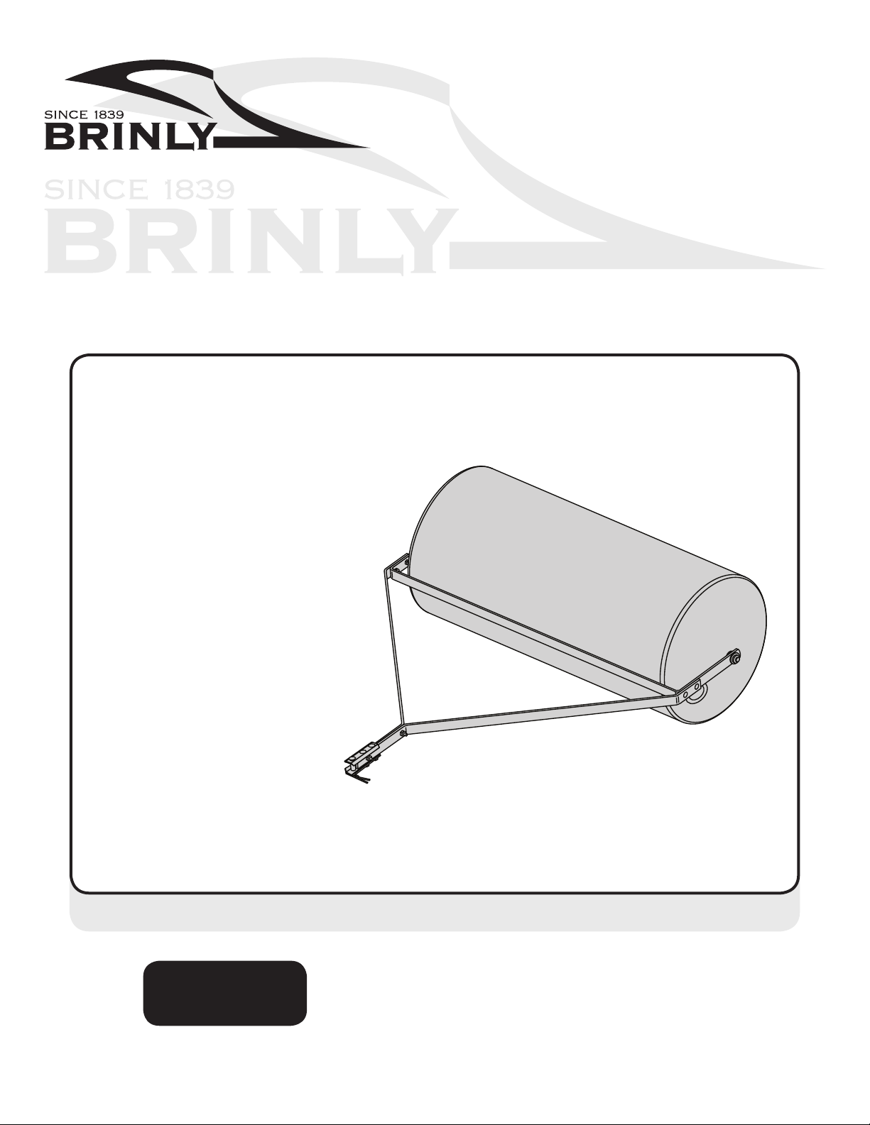
2L-1681BH-MEnglish Manual
INTRODUCTION AND SAFETY
SAFETY
=============================================
RULES FOR SAFE OPERATION
• Know controls and how to stop safely, READ THE OWNER’S
MANUAL before operating.
• Do not allow children to operate the vehicle, do not allow adults
to operate without proper instruction or without having read the
owner’s manual.
• Do not carry passengers. Keep children and pets a safe
distance away.
• Always wear substantial footwear. Do not wear loose tting clothing.
Do not wear loose tting clothing that can get caught in moving
parts.
• Keep your eyes and mind on your tractor / attachment and area
being covered. Do not let other interests distract you.
• Stay alert for holes in the terrain and other hidden hazards.
• Do not drive close to creeks, ditches and public highways.
• Watch out for trac when crossing or near roadways.
• When using any attachment, don’t allow anyone near the vehicle
while in operation.
• Keep the vehicle and attachment in good operating condition
and keep safety devices in place.
• Keep all nuts, bolts and screws tight to be sure the equipment
is in safe working condition.
• The vehicle and attachment should be stopped and inspected for
damage after striking a foreign object. The damage should be
repaired before restarting and operating the equipment.
• See tractor equipment owner’s manual for safe operation of the
equipment.
CUSTOMER RESPONSIBILITIES
- Please read & retain this manual. The instructions will enable to assemble and maintain your product properly.
- Please carefully read and observe the SAFETY SECTION of this manual.
- Follow a regular schedule in maintaining and caring for your Brinly-Hardy product.
CONGRATULATIONS on your new Brinly-Hardy Lawn Roller! This accessory has been designed, engineered and manufactured
to give you the best possible dependability and performance.
Should you experience any problem you cannot easily remedy, please do not hesitate to contact our knowledgeable customer
service department toll-free at 1-877-728-8224. We have competent, well trained technicians to help you with the assembly
and use of your Roller.
This symbol will help to point out important safety
precautions throughout this manual. It means -
ATTENTION! BECOME ALERT! Your safety is involved.
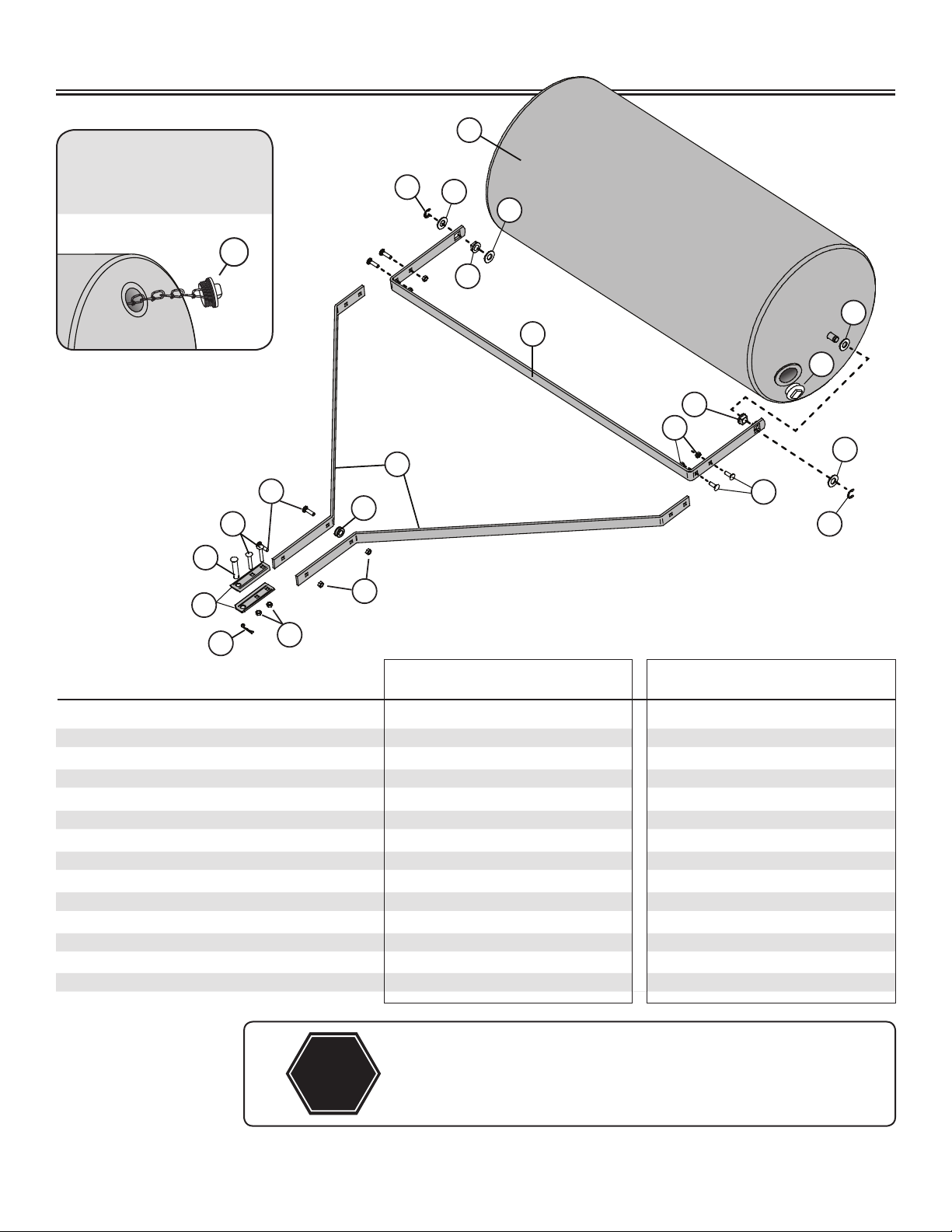
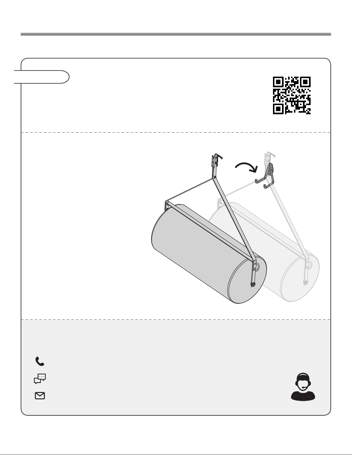
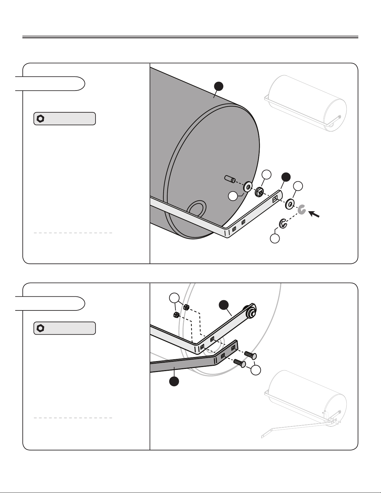
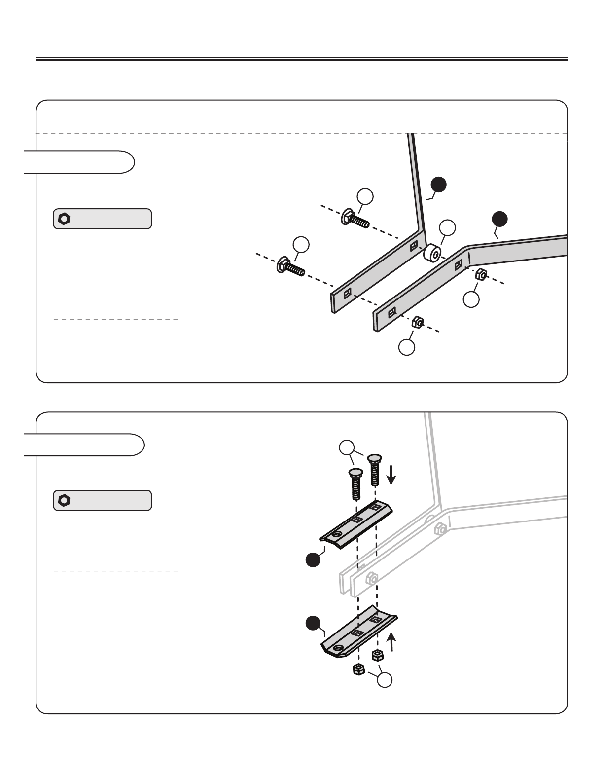
Tools Required
for Assembly:
• (x2) 1/2” Wrench
• (x2) 3/4” Wrench (PRC-241 BH Only)
• Slip Joint Pliers
TABLE OF CONTENTS
Safety ........................ 2
Hardware Identifier
and Part List .................. 3 - 5
Assembly ................... 6 - 10
Operation ...................... 11
Maintenance ................... 11
Warranty ......................12

3L-1681BH-M
English Manual
DO NOT RETURN PRODUCT IF YOU ARE MISSING PARTS.
Please Call: 1 (877) 728-8224
HARDWARE IDENTIFIER
Carriage Bolt
5/16 x 1”
(x4) . . . . . . . . . . . . . . . . . . . . . .
11M1016P
4
Carriage Bolt
5/16 x 1 1/2”
(x2) . . . . . . . . . . . . . . . .
11M1024P
5
Carriage Bolt
5/16 x 2 1/4”
(x2) . . . . . . .
11M1036P
6
Washer: Flat
5/8” (x4) . . . . . . .
45M2121P
7
Hitch Pin Cotter
(x1) . . . . . . . . . . . . . . . . .
14
D-146P
Hitch
Pin (x1)
. . . . . . . .
13
B-3861
Nut: Nylon Lock
5/16” (x8) . . . . . . . . . . .
8
B-4786
E-Ring, 5/8”
(x2) . . . . . . . . . . . . . .
11
F-577
PARTS IN ADDITIONAL HARDWARE BAG
(Only for PRC-241 BH)
Bolt: Hex Head
1/2 x 2-1/4”
(x1) . . . .
16
1M1636P
Nut: Hex
1/2” (x1) . . . . . . . . . .
17
30M1600P
Lock Washer 1/2”
(x1) . . . . . . . . . . . . . .
18
40M1600P
Illustrations on this page
are to scale for faster
identication of hardware
during assembly.

4L-1681BH-MEnglish Manual
PARTS
1
2
3
4
5
6
7
8
9
10
11
12
13
14
15
16
17
18
19
20
Frame Extension Bar 2
Roller Drum Assembly 1
Scraper Bar 1
5/16” x 1”, Carriage Bolt 4
5/16” x 1-1/2”, Carriage Bolt 2
5/16” x 2-1/4”, Carriage Bolt 2
5/8” Flat Washer 4
5/16” Nylon Lock Nut 8
Plug 1
Square Bearing 2
5/8” E-Ring 2
Frame Spacer 1
Hitch Pin 1
Hitch Pin Cotter 1
Handle 1
Hex Bolt 1/2” x 2-1/4 1
Hex Nut 1/2” 1
Lock Washer 1/2” 1
Grip 2
Clevis 2
Description Qty.Ref. #
5
21
31
20
14
9
3
2
1
4
6
11
01
8
7
7
8
8
7
7
11
01
16
15
19
18
17
B-3554-10
B-5121
B-6291-10
11M1016P
11M1024P
11M1036P
45M2121P
B-4786
1019261
B-6270
F-577
R-1141-01
B-3861
D-146P
B-3556-10
1M1636P
30M1600P
40M1600P
B-2579
R-892-10
PRC-241BH
B-3554-10
B-5121
B-6291-10
11M1016P
11M1024P
11M1036P
45M2121P
B-4786
1019524
B-6270
F-577
R-1141-01
B-3861
D-146P
B-3556-10
1M1636P
30M1600P
40M1600P
B-2579
R-892-10
PRC-241BH-A
B-6289-10
B-6271
B-6272-10
11M1016P
11M1024P
11M1036P
45M2121P
B-4786
1019261
B-6270
F-577
R-1141-01
B-3861
D-146P
PRT-361BH
B-6289-10
B-6271
B-6272-10
11M1016P
11M1024P
11M1036P
45M2121P
B-4786
1019524
B-6270
F-577
R-1141-01
B-3861
D-146P
PRT-361BH-A
Handle for the PRC-241BH
and PRC-241BH-A only

5L-1681BH-M
English Manual
PARTS
1
2
3
4
5
6
7
8
9
10
11
12
13
14
Frame Extension Bar 2
Roller Drum Assembly 1
Scraper Bar 1
5/16” x 1”, Carriage Bolt 4
5/16” x 1-1/2”, Carriage Bolt 2
5/16” x 2-1/4”, Carriage Bolt 2
5/8” Flat Washer 4
5/16” Nylon Lock Nut 8
Plug 1
Square Bearing 2
5/8” E-Ring 2
Frame Spacer 1
Hitch Pin 1
Hitch Pin Cotter 1
Description Qty.Ref. #
B-5357-10
B-5353-B
B-6292-10
11M1016P
11M1024P
11M1036P
45M2121P
B-4786
1019261
B-6270
F-577
R-1141-01
B-3861
D-146P
PRT-361SBH
B-5357-10
B-5353-B
B-6292-10
11M1016P
11M1024P
11M1036P
45M2121P
B-4786
1019524
B-6270
F-577
R-1141-01
B-3861
D-146P
PRT-361SBH-A
B-6290-10
B-5789-B
B-6294-10
11M1016P
11M1024P
11M1036P
45M2121P
B-4786
1019524
B-6270
F-577
R-1141-01
B-3861
D-146P
PRT-481SBHC-A
B-6290-10
B-5789-B
B-6294-10
11M1016P
11M1024P
11M1036P
45M2121P
B-4786
1019261
B-6270
F-577
R-1141-01
B-3861
D-146P
PRT-481SBH
STOP
Installation Questions? Missing Parts or Need Replacement Parts?
DON’T GO BACK TO THE STORE!
Please contact our Customer Service Department:
Call Toll Free: 877-728-8224 Or Email: customerservice@brinly.com
5
21
31
20
14
9
3
2
1
4
6
11
01
8
7
7
8
8
7
7
11
01
16
15
19
18
17
Handle for PRC-241 BH only
A Tethered Plug comes
with models: PRC-241BH-A,
PRT-361BH-A, PRT-361SBH-A
and PRT-481SBHC-A
9

6L-1681BH-MEnglish Manual
Assembly Tip
You can check out our step-by-step Lawn Roller assembly video
by visiting our Brinly YouTube page, Brinly.com, or by scanning
this QR code with your smartphone.
ASSEMBLY
WE RECOMMEND THE FOLLOWING STEPS
FOR THE CARE OF YOUR ROLLER TO PREVENT
FLAT SPOTS:
- For longest life, drain the roller
and leave the plug out.
If possible, hang the roller when not in
use to prevent the potential occurrence
of the drum developing a at spot.
- If a at spot develops during
storage, rst ensure the roller is empty.
Next, leave it out in the sun to warm
(we recommend sitting it out on
pavement for at least one day).
Once this is complete, roll it around
to reduce the at area.
If you have questions, are missing parts or need replacement parts, don’t go back to the store!
Please nd your product serial number and model number, then contact our Customer Service department:
In North America and Canada call Toll-Free: 877-728-8224
Chat online: www.brinly.com
Email: customerservice@brinly.com

7L-1681BH-M
English Manual
3
1
8
4
10
7
7
11
3
2
ASSEMBLY
Assembly Step 1
Attaching the Scraper Bar
Add a 5/8” at washer (7) to the
Roller Drum (2) as illustrated.
Slide a square bearing (10) into
the large square hole at the end of
the Scraper Bar (3) and add to the
Roller Drum.
Add another 5/8” at washer (7).
Secure everything in place by
sliding a 5/8” E-ring (11) into the
slot at the end of the roller drum (2).
Hardware Panel A
Repeat this step on the
other end of the drum.
Assembly Step 2
Repeat this step on the
other end of the drum.
Align the Frame Extension Bar (1)
as illustrated.
From the outside, run two
5/16 x 1” Carriage Bolts (4) through
the Extension Bar (1) and Scraper
Bar (3) as illustrated.
Secure everything in place with two
5/16” Nylon Lock Nuts (8).
Hardware Panel B

8L-1681BH-MEnglish Manual
1
1
5
5
12
8
8
NOTE: Do not tighten the lock nuts added on this step completely (until Assembly Step 4-A is complete).
Assembly Step 3
Connecting the Frame Extension Bars
Center the Spacer (12) between the second
hole of the Extension Bars (1) and run a
5/16” Carriage Bolt (5) through.
Loosely add a 5/16” Lock Nut (8).
Hardware Panel C
Add the second 5/16” Carriage bolt to
the Extension Bars (1) and secure with
the additional 5/16” Lock Nut (8).
Assembly Step 4
Align the Clevis plates (20)
as illustrated.
NOTE: The two bolts that will be added on
this step need to straddle the Carriage Bolt
at the very end of the extension bars.
Run two 5/16 x 2-1/4” Carriage
Bolts (6) through the Clevis Plates (20).
Secure in place with two 5/16” Nylon
Lock Nuts (8).
Hardware Panel D
Attaching the Clevis
20
20
6
8
ASSEMBLY

9L-1681BH-M
English Manual
15
16
18
17
Slide the Handle (15) between the Clevis
plates as illustrated. NOTE: Be sure to align
the openings of the clevis and handle.
Hardware Bag
Run a 1/2 x 2-1/4” Hex Bolt (16) through the Clevis
plates and handle. Secure with a 1/2” lock washer (18)
and a 1/2” lock nut (17).
Slide the grips (19)
over the ends of the
handle (15).
Assembly Step 6
If you are
assembling
PRC-241BH or
PRC-241BH-A:
Skip Step 5
and continue
to Assembly
Step 6
13
14
Assembly Step 5
Add the hitch pin (13) through remaining
openings of the Clevis (20) and secure
with a Hitch Pin Cotter (14).
Skip Step 6 and continue to Assembly Step 7.
Hardware Panel D
PRT-361 BH, PRT-361S BH & PRT-481S BH: Attaching the Clevis
PRC-241 BH: Attaching the Handle
15
19
19
ASSEMBLY

10 L-1681BH-MEnglish Manual
Assembly Step 7
Adding the Roller Plug
When installing the plug (9) please note the
plug has an o-ring, ensure o-ring properly
seats against the roller. A portion of the plug
will extend from the roller, however, it will not
interfere with the scraper bar (3).
Hand tighten as far as possible,
if the plug is leaking, ensure o-ring
is not bulging outside of the plug.
NOTE: A wrench around the plug handle
can be used to further tighten if necessary.
ADDITIONAL NOTE:
Some models come with a
tethered plug. This plug can be
attached by squeezing the tethered
spring. Next insert the plug into roller,
rotating the plug in place.
3
9
Assembly is complete.
9
ASSEMBLY

11 L-1681BH-M
English Manual
A
20
1. Park towing vehicle safely using the
parking brake (See towing vehicle
operator’s manual).
2. Align Cart Clevis (20) with towing
vehicle hitch plate.
3. Install the hitch pin (13) through the
Clevis (20) and secure with a Hitch
Pin Cotter (14).
1. Park towing vehicle safely and set the
parking brake (See towing vehicle
operator’s manual).
2. Remove Hairpin Cotter (14) and Hitch Pin
(13) from Clevis. Push Cart away from the
towing vehicle.
3. Reinstall Hitch Pin (13) and Hairpin Cotter
(14) to Clevis (20) for storage.
NOTE: Emptying the roller after each use
will reduce the occurrence of flat spots.
USE AND CARE
MODELS:
PRC-241BH
PRC-241BH-A
PRT-361BH
PRT-361BH-A
PRT-361SBH
PRT-361SBH-A
PRT-481SBH
PRT-481SBHC-A
INSTALLING THE ROLLER
REMOVING THE ROLLER
SPECIFICATIONS
Best Speed for
Quality Results ....3 mph
PRT-361BH, PRT-361SBH and PRT-481SBH
CAUTION: AVOID INJURY!
Keep body parts away from under
Drawbar and Bed.
CAUTION: AVOID INJURY!
Keep body parts away from under
Drawbar. Do not attempt to disconnect
Cart from towing vehicle with weight
in the Bed.
A
20
13
14
13
14
Working Width .... 24”
Max. Drum
Capacity .... 28 gallons
Working Width .... 36”
Max. Drum
Capacity .... 76 gallons
Working Width .... 36”
Max. Drum
Capacity .... 42 gallons
Working Width .... 48”
Max. Drum
Capacity .... 54 gallons
PRC-241BH (-A)
PRT-361BH (-A)
PRT-361SBH (-A)
PRT-481SBH (C-A)

12 L-1681BH-MEnglish Manual
USE AND CARE
• The key to years of
trouble-free service is to
keep your Lawn Roller
clean and dry.
• Occasionally check all moving parts for free
movement and, if necessary, lubricate with oil.
• Should rust develop, sand lightly and then paint
area with enamel.
• Periodically check all fasteners for tightness.
We recommend the following steps for
the care of your Roller to prevent at spots:
If a at spot develops during storage, rst ensure
the roller is empty. Next, leave it out in the sun to
warm (we recommend sitting it out on pavement
for at least one day).
Once this is complete, roll it around to reduce
the at area.
MAINTENANCEOPERATION
• Refer to tractor manual to determine proper
towing capacity of your Tractor / Rider.
• Fill the roller with amount of
water recommended for your tractor / rider.
Screw in the plug and tighten securely.
• The plug has an o-ring to create a seal and
prevents the drum contents from leaking out.
• For longest life, drain the roller, leave the
plug out, and if possible, hang the roller
when not in use to prevent possibility of
developing a at spot.
• If a at spot develops on the roller during storage, ensure
roller is empty then leave out in the sun to warm and roll
around to reduce at area.
• Please note that sand may be used
in place of water with no risk of freezing.
• Ground condition is vital to good leveling.
Soil should be moist, but not muddy.
• Refer to your Tractor or Riding Mower Owner’s manual for
proper towing capacity and safe operation of your towing
equipment. Towing / Stopping distances will be greatly
aected by added weight of roller.
CAUTION! Do not overload your Tractor / Rider.
Roller fully loaded with water weighs:
PRC-241BH & PRC-241BH-A = 270 lbs
PRT-361BH & PRT-361BH-A = 690 lbs
PRT-361SBH & PRT-361SBH-A = 390 lbs
PRT-481SBH & PRT-481SBHC-A = 485 lbs
Rollers yield the best results when ground
conditions are correct, and equipment is
operating at less than 3 mph.
CALIBRATING YOUR TRACTOR
TO 3 MPH:
Measure a distance of 20 feet on a flat,
level surface. Adjust tractor throttle and
select a gear to cover this distance in 4.5
seconds.
TRACTOR / RIDING
MOWER SPEED
If possible, hang the roller when not in use to
prevent the potential occurrence of the drum
developing a at spot.
For longest life, drain the roller and leave
the plug out.

13 L-1681BH-M
English Manual
USE AND CARE
QUALITY CONTINUES
WITH QUALITY SERVICE
If you have installation questions, are missing parts or need
replacement parts, don’t go back to the store!
Please find your product serial number and model number,
then contact our Customer Service department:
In North America and Canada call
Toll-Free: 877-728-8224
Chat online: www.brinly.com
Email: customerservice@brinly.com
SERVICE
OPTIONAL ACCESSORIES
MAGNETIC HITCH PIN
MHPK-12BH
This quick-connect
magnetic hitch pin can replace
a regular cotter pin for an
extra-strong, convenient
upgrade.
- Diameter: 1/2”
- Pin Length: 3”
NOTE:
Additional accesories are also available in
our Parts Store online: shop.brinly.com
STANDARD PLUG
1019261
This is our standard
plug, compatable with
all the roller
models.
TETHERED PLUG
1019524
The tethered plug can
be attached, compatable
with all roller
models.
ONLINE
PRC-241BH
and PRC-241BH-A
PRT-481SBH
and PRT-481SBHC-A
PRT-361SBH
and PRT-361SBH-A
PRT-361BH
and PRT-361BH-A
Additional info and videos are available on our website
( www.brinly.com ) OR scan one of the following QR codes:

14 L-1681BH-M
Brinly-Hardy Company warrants the products listed below against
defects in material and workmanship, and will at its option, repair or
replace, free of charge, any part found to be defective in materials
or workmanship. This limited warranty shall only apply if this prod-
uct has been assembled, operated, and maintained in accordance
with the Operator’s manual furnished with the product, and has not
been subject to misuse, abuse, commercial use, neglect, accident,
improper maintenance, alteration, vandalism, theft, re, water, or
damage because of other peril or natural disaster.
Parts found to be defective within the warranty period will be re-
placed at our expense. Our obligation under this warranty is ex-
pressly limited to the replacement or repair, at our option, of parts
found to be defective in material and workmanship.
HOW TO OBTAIN SERVICE:
Warranty parts replacements are
available, only with proof of purchase, through our Customer Ser-
vice Department. Call 877-728-8224.
No implied warranty, including any implied warranty of mer-
chantability of tness for a particular purpose, applies after
the applicable period of express written warranty above as to
the part as identied below. No other express warranty whether
written or oral, except as mentioned above, given by any per-
son or entity, including a dealer or retailer, with respect to any
product, shall bind Brinly-Hardy Co. During the period of the
warranty, the exclusive remedy is repair or replacement of the
product as set forth above.
The provisions as set forth in this warranty provide the sole
and exclusive remedy arising from the sale. Brinly-Hardy Co.
shall not be liable for incidental or consequential loss or dam-
age including, without limitation, expenses incurred for substi-
tute or replacement lawn care services or for rental expenses to
temporarily replace a warranted product.
Some states do not allow the exclusion or limitation of incidental or
consequential damages, or limitations on how long an implied warran-
ty lasts, so the above exclusions or limitations may not apply to you.
During the warranty period, the exclusive remedy is replacement of
the part. In no event shall recovery of any kind be greater that the
amount of the purchase price of the product sold. Alteration of safety
features of the product shall void this warranty. You assume the risk
and liability for loss, damage, or injury to you and your property and/
or to others and their property arising out of the misuse or inability
to use this product. NOTE: This limited warranty shall not extend to
anyone other than the original purchaser or to the person for whom
it was purchased as a gift.
This limited warranty lasts as long you own your product purchased
from an authorized seller. Coverage terminates once you sell or
otherwise transfer the product.
This limited warranty does not cover any purchaser other than the
original purchaser of the product, nor does it cover any product pur-
chased from an unauthorized third-party. If you are not the original
purchaser of this product, your product is not covered by our limited
warranty and you take the product “AS IS” and “with all faults.”
We may require proof of purchase from you demonstrating that you
are the original purchaser of the product, purchased the product from
an authorized dealer, and are eligible to make a valid claim under this
limited warranty.
How state law relates to this warranty: This limited warranty gives
you specic legal rights, and you may also have other rights which
vary from state to state.
IMPORTANT:
The Warranty period stated below begins with the proof of purchase.
Without the proof of purchase, the Warranty period begins from the
date of manufacture determined by the serial number manufacturing
date. All parts replaced under warranty will be considered as part
of the original product, and any warranty on the replaced parts will
expire coincident with the original product warranty.
The limited warranty set forth below is given by Brinly-Hardy Company with respect to new
merchandise purchased and used in the United States (its possessions and territories) and Canada.
This limited warranty does not provide coverage
in the following cases:
a. Routine maintenance items such as lubricants & lters.
b. Normal deterioration of exterior nish due to use or exposure.
c. Transportation and/or labor charges.
d. The warranty does not include commercial and/or rental use.
MANUFACTURER’S LIMITED WARRANTY
ROLLERS
If this equipment is being used in a commercial application and / or for
multiple properties, the warranty is 90 days after purchase for all parts.
WARRANTY PERIOD:
See applicable parts listed below.
Standard / Residential Use:
Steel Frame & Steel Parts ............. 2 years
Roller Drum ........................ 2 years
All other normal wear parts or component failures
will be covered on this product for a period of 90 days.
Brinly-Hardy Company • 3230 Industrial Parkway • Jeersonville, IN 47130 • (877) 728-8224 • brinly.com
This manual suits for next models
7
Table of contents
Other Brinly Farm Equipment manuals