manuals.online logo
Brands
  1. Home
  2. •
  3. Brands
  4. •
  5. Bosch
  6. •
  7. Control Unit
  8. •
  9. Bosch ReadykeyPRO LNL-1200 User manual

Bosch ReadykeyPRO LNL-1200 User manual

LNL-1200 Output Control Module
Quick Reference Guide
For detailed information, please refer to the LNL-1200 tab in the READYKEYPRO Hardware Installation Guide
(49289).
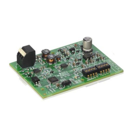
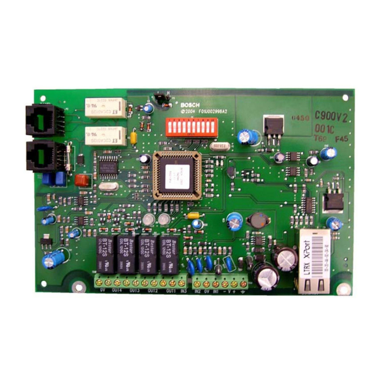
1.0 The Output Control Module Board
The Output Control Module board
contains the following components:
A. sixteen (16) alarm output
relays with
B. sixteen (16) corresponding
status LEDs
C. two (2) unsupervised alarm
inputs
D. one (1) RS-485 interface
E. one (1) power input
F. eight (8) dip switches
G. three (3) jumpers
H. two (2) status LEDs
Figure 1: LNL-1200
LNL-1200
LNL-1200 Quick Reference Guide
49307C Page 2 © 2006 Bosch Security Systems, Inc.
2.0 Specifications
The Output Control Module is for use in low voltage, class 2 circuit only.
Primary Power:
DC input 12 VDC @ 850 mA
24 VDC @ 450 mA
Communication Ports Port 1 Port 1: RS-485 (2-wire or 4-wire), 2400 to 38400 bps async
Cabinet Tamper
Monitor unsupervised, dedicated
Inputs
Power Fault
Monitor unsupervised, dedicated
Outputs Sixteen (16) form C dry-contact relays, 5 A @ 28 VDC resistive
Power 1 twisted pair, 18 AWG
RS-485 24 AWG twisted pair(s) with shield, 4000 ft (1200 m)
Inputs twisted pair, 30 ohms maximum
Wire Requirements
Outputs as required for the load
Temperature 0 to 70°C, operating
-55 to +85 °C, storage
Environmental
Humidity 0 to 95% RHNC
Dimension
(HxWxD) 1 in. x 6 in. x 8 in.
(25 mm x 152 mm x 203 mm)
Mechanical
Weight Weight: 16 oz. (454 g) nominal
Table 1: LNL-1100 Specifications
3.0 Installation
3.1 Unsupervised Alarm Inputs: Power Fault and Cabinet Tamper Monitors
Wire the BA (power fault) and CT (cabinet
tamper) inputs using a twisted pair cable, 30
ohms maximum (no EOL resistors required).
If either of these inputs is not used, a jumper
wire should be installed.
3.2 Upstream Controller
Communication to the Intelligent
System Controller
GND
CABINET
TAMPER
POWER
FAULT GND
CT
BA
Figure 2: Unsupervised Alarm Input Wiring
The RS-485 is
asynchronous,
half-duplex, using 1
start bit, 8 data
bits, 1 stop bit.
TR2+
GND
TR3+
TR3-
TR2-
GND
LNL-500
TR+
R+
R-
TR-
GND
Figure 3: RS-485 2-Wire Communications
T
R
2
+
T
R
2
-
G
N
D
T
R
3
+
T
R
3
-
G
N
D
T
R
+
T
R
-
R
+
R-
S
G
LNL-500
OUTPUT CONTROL
BOARD
Figure 4: RS-485 4-Wire
Communications
LNL-1200
LNL-1200 Quick Reference Guide
© 2006 Bosch Security Systems, Inc. Page 3 49307C
3.3 Power Source Wiring
If Using a 12 VDC Power Source, be sure to observe
polarity. VIN
GND
12 to 24 VDC
+
-
Figure 5: Power Source Wiring
3.4 Relay Outputs
DC SOURCE
AC SOURCE
NC
C
NO
NC
C
NO
FUSE +
-
LOAD
LOAD
MOV
FUSE
Figure 6: Relay Outputs
3.5 Configuration
The LNL Output Control Board contains (8) DIP switches and (3) jumpers that must be configured for your
system.
3.6 Setting DIP Switches DIP Switch(es) Used to configure:
1, 2, 3, 4, 5 Device Communication address (0-31)
6, 7 Communication baud rate
(38400, 19200, 9600 bps)
8 Not used
The default positions for DIP switches is: Address
00; 38,400 bps (switches 6 and 7 are on, others
are off).
12345678
Figure 7: DIP Switch Settings
Table 2: DIP Switch explanations
3.7 Communication Baud Rate DIP SWITCHBaud Rate
(bps) 6 7
38400 ON ON
19200 OFF ON
9600 ON OFF
0 OFF OFF
To configure the communication baud rate, set DIP switches 6 and
7 according to Table 3.
Table 3: Setting Baud Rate
© 2006 Bosch Security Systems, Inc.
130 Perinton Parkway, Fairport, NY 14450-9199 USA
Customer Service: (800) 289-0096; Technical Support: (888) 886-6189
49307C
Quick Reference Guide 10/06
LNL-1200
Page 4 of 4
3.8 Device Addresses
To configure the device communication address, set DIP switches 1, 2, 3, 4, and 5 according to Table 4.
DIP SWITCH DIP SWITCH
ADDRESS 5: 4: 3: 2: 1: ADDRESS 5: 4: 3: 2: 1:
0 OFF OFF OFF OFF OFF 16 ON OFF OFF OFF OFF
1 OFF OFF OFF OFF ON 17 ON OFF OFF OFF ON
2 OFF OFF OFF ON OFF 18 ON OFF OFF ON OFF
3 OFF OFF OFF ON ON 19 ON OFF OFF ON ON
4 OFF OFF ON OFF OFF 20 ON OFF ON OFF OFF
5 OFF OFF ON OFF ON 21 ON OFF ON OFF ON
6 OFF OFF ON ON OFF 22 ON OFF ON ON OFF
7 OFF OFF ON ON ON 23 ON OFF ON ON ON
8 OFF ON OFF OFF OFF 24 ON ON OFF OFF OFF
9 OFF ON OFF OFF ON 25 ON ON OFF OFF ON
10 OFF ON OFF ON OFF 26 ON ON OFF ON OFF
11 OFF ON OFF ON ON 27 ON ON OFF ON ON
12 OFF ON ON OFF OFF 28 ON ON ON OFF OFF
13 OFF ON ON OFF ON 29 ON ON ON OFF ON
14 OFF ON ON ON OFF 30 ON ON ON ON OFF
15 OFF ON ON ON ON 31 ON ON ON ON ON
Table 4: DIP Switch Device Addresses
1
J3
2
3
2-Wire
1
J3
2
3
4-Wire
3.9 Installing Jumpers
3.9.1 RS-485 Type
Jumper J3 is used to configure the RS-485 type for Port 1 on the
READYKEYPRO Output Control Board. There are two possible
configuration options that can be used to install this jumper: 2-wire
configuration, and 4-wire configuration.
Figure 8: RS-485
configuration for Jumper J3
J2
J1
J2
J1
“ON” Configuration for J1, J2 “Not ON” Configuration for J1, J2
3.9.2 RS-485 EOL
Terminator
Status
Figure 9: Jumper J5 & J6 Configuration

Other Bosch Control Unit manuals

Bosch FLM-420-NAC-D User manual

Bosch

Bosch FLM-420-NAC-D User manual

Bosch MC 400 User manual

Bosch

Bosch MC 400 User manual

Bosch FLM-420-EOL2W-W User manual

Bosch

Bosch FLM-420-EOL2W-W User manual

Bosch Sensortec Application Board 3.0 User manual

Bosch

Bosch Sensortec Application Board 3.0 User manual

Bosch IOS 0232 A User manual

Bosch

Bosch IOS 0232 A User manual

Bosch B426 User manual

Bosch

Bosch B426 User manual

Bosch ATB 420 LSNi Installation and operation manual
Bosch

Bosch ATB 420 LSNi Installation and operation manual

Bosch Rexroth IndraControl XFE 01.1 Series User manual

Bosch

Bosch Rexroth IndraControl XFE 01.1 Series User manual

Bosch D113 User manual

Bosch

Bosch D113 User manual

Bosch D132A User manual

Bosch

Bosch D132A User manual

Bosch Professional GCY 42 Assembly instructions

Bosch

Bosch Professional GCY 42 Assembly instructions

Bosch RC 4001 User manual

Bosch

Bosch RC 4001 User manual

Bosch API-AMC2-4WE User manual

Bosch

Bosch API-AMC2-4WE User manual

Bosch C-IR 20 User manual

Bosch

Bosch C-IR 20 User manual

Bosch B901 User manual

Bosch

Bosch B901 User manual

Bosch D8128D User manual

Bosch

Bosch D8128D User manual

Bosch KTS 5 Series User manual

Bosch

Bosch KTS 5 Series User manual
Bosch ConnectModule BCM3100 User manual

Bosch

Bosch ConnectModule BCM3100 User manual

Bosch Rexroth R-IB IL 24 PSDO 8-PAC User manual

Bosch

Bosch Rexroth R-IB IL 24 PSDO 8-PAC User manual

Bosch Rexroth ctrlX I/O XI332204 User manual

Bosch

Bosch Rexroth ctrlX I/O XI332204 User manual

Bosch Control 8313 Operating instructions

Bosch

Bosch Control 8313 Operating instructions

Bosch Denoxtronic 2.1 Technical specifications

Bosch

Bosch Denoxtronic 2.1 Technical specifications

Bosch 715ES Reference manual

Bosch

Bosch 715ES Reference manual

Bosch Rexroth 4WS2EM 10 Series User manual

Bosch

Bosch Rexroth 4WS2EM 10 Series User manual

Popular Control Unit manuals by other brands

LAM Technologies DS10 Series user manual

LAM Technologies

LAM Technologies DS10 Series user manual

Danfoss ECL Comfort 210 installation guide

Danfoss

Danfoss ECL Comfort 210 installation guide

ABB REC 523 Technical reference manual

ABB

ABB REC 523 Technical reference manual

Hynautic 04 Series Installation and service

Hynautic

Hynautic 04 Series Installation and service

Waveshare SIM7600CE-T quick start guide

Waveshare

Waveshare SIM7600CE-T quick start guide

Ideal-Standard Easybox Slim Series installation instructions

Ideal-Standard

Ideal-Standard Easybox Slim Series installation instructions

Boltek RLO-10 installation instructions

Boltek

Boltek RLO-10 installation instructions

Afag RM 63 instructions

Afag

Afag RM 63 instructions

JYTEK JY5312 user manual

JYTEK

JYTEK JY5312 user manual

ADLINK Technology HSL-DI32-UD quick start guide

ADLINK Technology

ADLINK Technology HSL-DI32-UD quick start guide

Lenze E94AYCET Mounting instructions

Lenze

Lenze E94AYCET Mounting instructions

Siemens 3VL93 Series operating instructions

Siemens

Siemens 3VL93 Series operating instructions

Valve Concepts 1078 Installation, operation and maintenance manual

Valve Concepts

Valve Concepts 1078 Installation, operation and maintenance manual

DEICO DE9005 manual

DEICO

DEICO DE9005 manual

Kessel Comfort PLUS Installation and operating instructions

Kessel

Kessel Comfort PLUS Installation and operating instructions

ABB ACS880-04F Hardware manual

ABB

ABB ACS880-04F Hardware manual

GSD DT13R2611 quick start guide

GSD

GSD DT13R2611 quick start guide

Val-Matic Swing-Flex Check Valve Operation, maintenance and installation manual

Val-Matic

Val-Matic Swing-Flex Check Valve Operation, maintenance and installation manual

manuals.online logo
manuals.online logoBrands
  • About & Mission
  • Contact us
  • Privacy Policy
  • Terms and Conditions

Copyright 2025 Manuals.Online. All Rights Reserved.