2
SAVE THESE INSTRUCTIONS
READ ALL INSTRUCTIONS BEFORE USING THIS APPLIANCE
WARNING
To reduce the risk of fire, electric shock or injury:
1. Do not use on wet surfaces or outdoors.
2. Do not vacuum liquids or fine powders (such as drywall dust).
3. Do not use to pick up flammable or combustible liquids such
as gasoline or use in areas where they may be present.
4. Do not pick up anything that is burning or smoking, such as
cigarettes, matches, or hot ashes.
5. Do not allow to be used as a toy.Close attention is necessary
when used by or near children.
6. Use only as described in this manual. Use only
manufacturer's recommended attachments.
7. Keep hair, loose clothing, fingers and all parts of body away
from openings and moving parts.
8. Turn off all controls before unplugging.
9. Use extra care when cleaning on stairs.
10. Do not handle plug or appliance with wet hands.
11. Do not use with damaged cord or plug. If appliance is not
working as it should, if it has been dropped, damaged,
left outdoors, or dropped into water, return it to a Service
Center.
12.Keep your work area well lighted.
13.Connect to a properly grounded outlet only. See grounding
instructions shown on page 9.
14.When performing installation, servicing or cleaning the unit,
it is recommended to wear safety glasses and gloves.
15.When applicable local regulations comprise more
restrictive installation and/or certification requirements,
the aforementioned requirements prevail on those of this
document and the installer agrees to conform to these at
his own expenses.
CAUTION
1. Do not put any object into openings. Do not use with any
opening blocked; keep free of dust, lint, hair and anything
that may reduce air flow.
2. Ensure air flows freely and exhausts unobstructed from top
or side outlet.
3. Do not use without filter (or filters, according to the model)
in place.
4. Do not use to blow leaves or debris.
5. Do not place any object on top of the unit.
6. Do not install the unit horizontally.
7. Do not use the pail as a wash bucket.
8. Do not use the pail as a stool.
9. Avoid picking up sharp objects.
10. This appliance is for use on a standard 120 VAC, dedicated
15-amp branch circuit. Some brands of house panel
breakers may be more sensitive to startup current than
others (for example, Square D brand). In the event where
nuisance tripping of the house panel breaker occurs*, we
recommend changing the breaker with an “HM” type of the
same AMP rating.
*after ensuring that the circuit is DEDICATED to the central
vacuum unit, meaning that there is no other electrical
device connected to the central vacuum unit circuit.
11. Do not unplug the unit by pulling on cord. To unplug, grasp
the plug, not the cord.
12.Store your vacuum cleaner indoors in a clean, dry area, and
away from extreme temperatures.
13.Any servicing other than that recommended in this manual
should be performed by an authorized service facility.
14.We recommend that your unit be inspected by a specialized
technician once a year.
!
IMPORTANT SAFETY INSTRUCTIONS
When using an electrical appliance, basic precautions should always be followed, including the following:
GENERAL INFORMATION . . . . . . . . . 3
TOOL LISTING . . . . . . . . . . . . . . . . . . . . .3
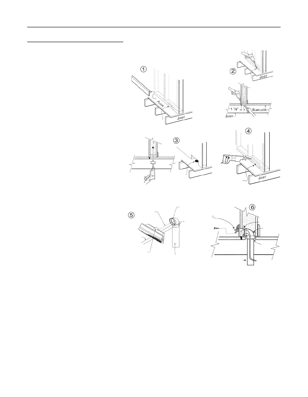
WORKING WITH PLASTIC TUBING. . . . . . . . . . . . . 3
WALL INLET INSTALLATION . . . . . . . . 3
V600W VACUSWEEP®
INLET VALVE INSTALLATION . . . . . . 4-6
CONNECTION FROM BELOW . . . . . . . . . . . . . . .4
CONNECTION FROM BEHIND . . . . . . . . . . . . . . .5
CONNECTION IN AWALL . . . . . . . . . . . . . . . . 6
POWER UNIT INSTALLATION . . . . . . 7-9
LOCATING THE POWER UNIT . . . . . . . . . . . . . .7
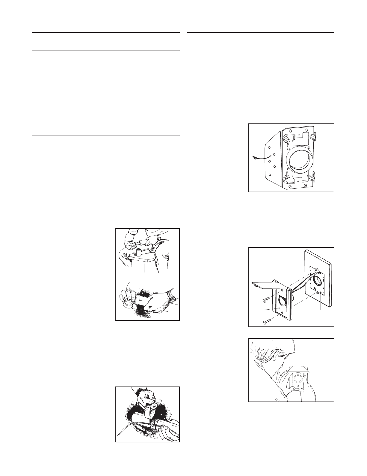
CHANGING INTAKE LINE DIRECTION . . . . . . . . . . .7
MOUNTING THE POWER UNIT . . . . . . . . . . . . . .8
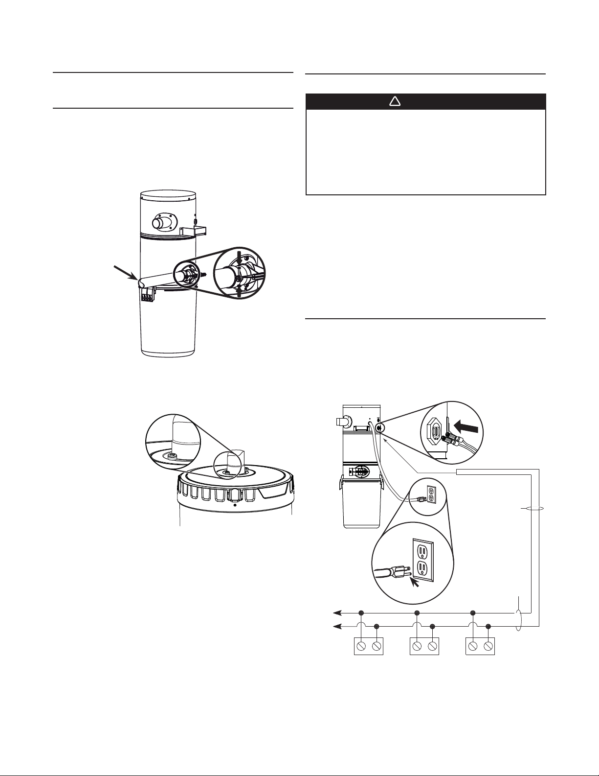
FITTING MAIN LINE TO POWER UNIT . . . . . . . . . . .9
GROUNDING INSTRUCTIONS . . . . . . . 9
WIRING . . . . . . . . . . . . . . . . . . . . . . . .9
OPERATION AND MAINTENANCE . . .10-11
WHEN TO CHANGE BAG OR EMPTY DEBRIS PAIL . . . . 10
HOW TO EMPTY DEBRIS PAIL
(BQ2 AND BQ3 POWER UNITS ONLY) . . . . . . . . . 10
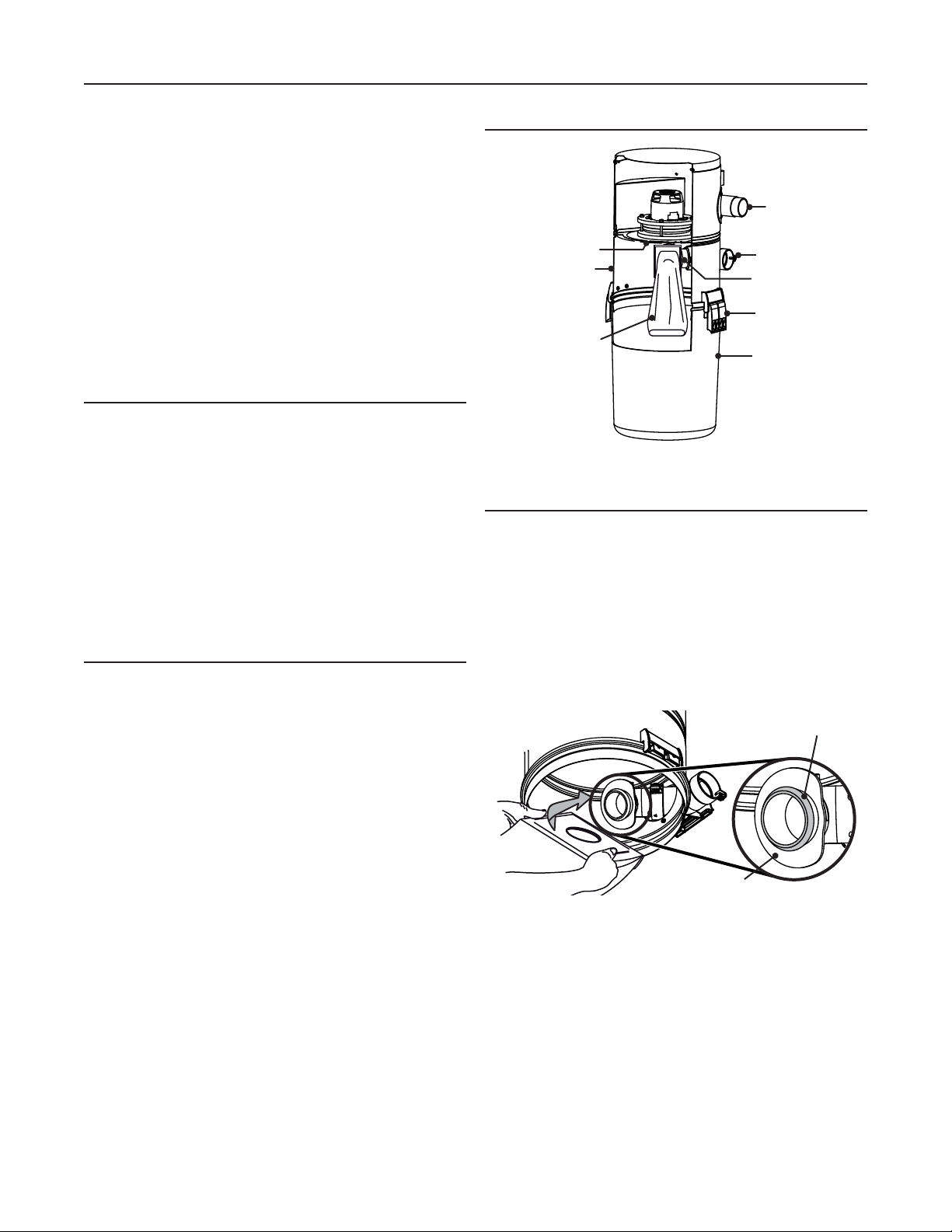
BQ1 POWER UNIT DETAILED VIEW . . . . . . . . . . 10
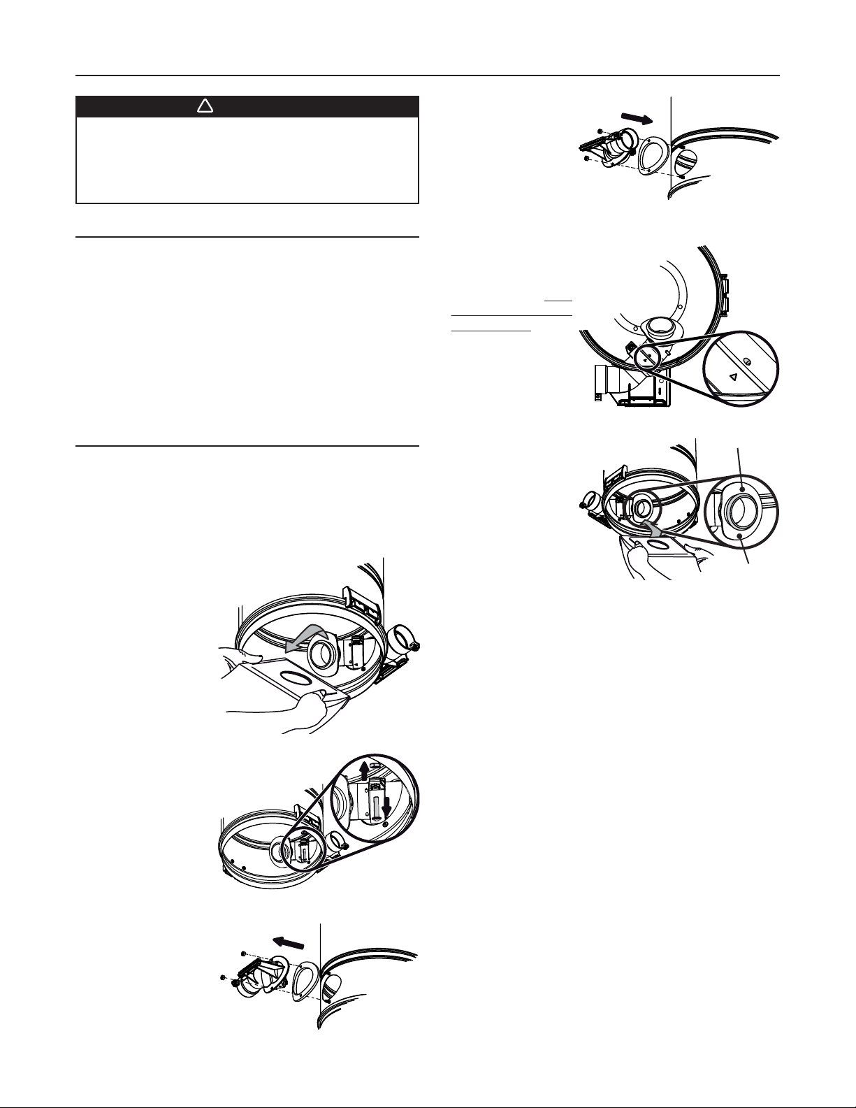
DISPOSABLE BAG REPLACEMENT
(BQ1 POWER UNIT ONLY) . . . . . . . . . . . . . . 10
PERMANENT FILTER
(BQ2 AND BQ3 POWER UNITS ONLY) . . . . . . . . . 11
REMOVAL AND INSTALLATION OF PERMANENT FILTER
(BQ2 AND BQ3 POWER UNITS ONLY) . . . . . . . . . 11
MOTOR FOAM FILTER (ALL UNITS) . . . . . . . . . . . 11
TROUBLESHOOTING GUIDE. . . . . . . 12
SERVICE PARTS . . . . . . . . . . . . . 13
WARRANTY . . . . . . . . . . . . . . . . 14
TABLE OF CONTENTS