Broan QTR Series User manual

Page 1
MODELS QTR090RC • QTR110RC • QTRE090RC
WARNING
TO REDUCE THE RISK OF FIRE, ELECTRIC SHOCK, OR
INJURY TO PERSONS, OBSERVE THE FOLLOWING:
1. Use this unit only in the manner intended by the manufacturer.
If you have questions, contact the manufacturer at the address
or telephone number listed in the warranty.
2. Before servicing or cleaning unit, switch power off
at service panel and lock the service disconnecting means
to prevent power from being switched on accidentally. When
the service disconnecting means cannot be locked, securely
fasten a prominent warning device, such as a tag, to the
service panel.
3. Installation work and electrical wiring must be done by a
qualified person(s) in accordance with all applicable codes
and standards, including fire-rated construction codes and
standards.
4. Sufficient air is needed for proper combustion and exhausting of
gases through the flue (chimney) of fuel burning equipment to
prevent backdrafting. Follow the heating equipment manufacturer’s
guideline and safety standards such as those published by
the National Fire Protection Association (NFPA), and the
American Society for Heating, Refrigeration and Air Conditioning
Engineers (ASHRAE), and the local code authorities.
5. When cutting or drilling into wall or ceiling, do not damage
electrical wiring and other hidden utilities.
6. Ducted fans must always be vented to the outdoors.
7. Acceptable for use over a tub or shower when connected to
a GFCI (Ground Fault Circuit Interrupter) - protected branch
circuit (ceiling installation only).
8. This unit must be grounded.
9. This ventilating fan is linked to the furnace motor. When servicing
the fan, disconnect power to furnace.
CAUTION
!
1. For general ventilating use only. Do not use to exhaust hazardous
or explosive materials and vapors.
2. To avoid motor bearing damage and noisy and/or unbalanced
impellers, keep drywall spray, construction dust, etc. off power
unit.
3. Please read specification label on product for further information
and requirements.
QTR/QTRE SERIES
QUIET VENTILATION FANS
WITH RELAY SWITCH
READ AND SAVE THESE INSTRUCTIONS
CLEANING & MAINTENANCE
WARRANTY
BROAN THREE-YEAR LIMITED WARRANTY
Broan warrants to the original consumer purchaser of its products that
such products will be free from defects in materials or workmanship for
a period of three years from the date of original purchase. THERE ARE
NO OTHER WARRANTIES, EXPRESS OR IMPLIED, INCLUDING, BUT
NOT LIMITED TO, IMPLIED WARRANTIES OF MERCHANTABILITY OR
FITNESS FOR A PARTICULAR PURPOSE.
During this three-year period, Broan will, at its option, repair or replace,
without charge, any product or part which is found to be defective under
normal use and service.
THIS WARRANTY DOES NOT EXTEND TO FLUORESCENT LAMP
STARTERS AND TUBES. This warranty does not cover (a) normal
maintenance and service or (b) any products or parts which have been
subject to misuse, negligence, accident, improper maintenance or
repair (other than by Broan), faulty installation or installation contrary to
recommended installation instructions.
The duration of an implied warranty is limited to the three-year period
as specified for the express warranty. Some jurisdiction do not allow
limitation on how long an implied warranty lasts, so the above limitation
may not apply to you.
BROAN’S OBLIGATION TO REPAIR OR REPLACE, AT BROAN’S
OPTION, SHALL BE THE PURCHASER’S SOLE AND EXCLUSIVE
REMEDY UNDER THIS WARRANTY. BROAN SHALL NOT BE
LIABLE FOR INCIDENTAL, CONSEQUENTIAL OR SPECIAL DAMAGES
ARISING OUT OF OR IN CONNECTION WITH PRODUCT USE OR
PERFORMANCE. Some jurisdiction do not allow the exclusion or
limitation of incidental or consequential damages, so the above limitation
may not apply to you.
This warranty gives you specific legal rights, and you may also have other
rights, which vary from province to province. This warranty supersedes all
prior warranties.
To qualify for warranty service, you must (a) notify Broan at the address
or telephone number stated below, (b) give the model number and part
identification and (c) describe the nature of any defect in the product or
part. At the time of requesting warranty service, you must present evidence
of the original purchase date.
Broan-NuTone Canada, 1140 Tristar Drive, Mississauga, Ontario L5T 1H9
(1-888-882-7626) (1-800-637-1453)
Installer: Leave this manual with the homeowner.
For quiet and efficient operation, long life, and attractive appearance -
lower or remove grille and vacuum interior of unit with the dusting
brush attachment.
The motor is permanently lubricated and never needs oiling. If the
motor bearings are making excessive or unusual noises, replace
the motor with the exact service motor. The impeller should also
be replaced.
OPERATION
Use an on/off switch or speed control to operate this ventilator.
See “Connect Wiring” for details.
BB0001

Page 2
MODELS QTR090RC • QTR110RC • QTRE090RC
TYPICAL INSTALLATIONS
BH
000
1A
Housing mounted
to I-joists.
Housing mounted
anywhere between
trusses using
hanger bars.
PLAN THE INSTALLATION
ROOF CAP *
4-IN. ROUND
ELBOW *
4-IN. ROUND
DUCT *
WALL
CAP *
*Purchase
separately
The unit will operate most quietly and efficiently when located
where the shortest possible duct run and minimum number of
elbows will be needed.
Use a roof cap or wall cap that has a built-in damper to reduce
backdrafts.
Plan to supply the unit with proper line voltage and appropriate
power cable.
A
Housing mounted
anywhere between
I-joists using
hanger bars.
Housing mounted
to joists.
Housing mounted
anywhere between
joists using
hanger bars.
Housing mounted
anywhere between
trusses using
hanger bars.
BH0006A
Cooking
Equipment
Floor
Do not install above or
inside this area.
45
o
45
o
BH0007A

Page 3
MODELS QTR090RC • QTR110RC • QTRE090RC
BJ0002
BJ0001
2. Attach
damper/duct
connector.
Snap damper/
duct connector
onto housing.
Make sure
connector is flush
with top of housing
and damper flap
falls closed.
3. Install
4-inch round
ductwork.
Connect 4-inch
round ductwork
to damper/duct
connector. Run
ductwork to a
roof cap or wall
cap. Tape all
ductwork
connections
to make them
secure and air tight.
INSTALL HOUSING & DUCT
BD0001
1a.Mount
housing to
joist or I-joist.
Use a pliers to bend
housing TABS out
to 900. Hold housing
in place so that
the housing tabs
contact the bottom
of the joist. The
housing mounts
with four (4) screws
or nails. Screw
or nail housing to
joist through lowest
holes in each
mounting flange,
then through
highest holes.
NOTE: Mounting to
I-JOIST (shown)
requires use
of SPACERS
(included) between
the highest hole
of each mounting
flange and the
I-joist.
SPACER
(use for mounting to I-Joist)
I-JOIST
TABS
1b.Mount housing anywhere between
trusses, joists, or I-joists using hanger
bars.
Sliding hanger bars are provided to allow for accurate
positioning of housing anywhere between framing. They can
be used on all types of framing (I-joist, standard joist, and
truss construction) and span up to 24”.
Attach the MOUNTING CHANNELS to the housing using the
SCREWS supplied. Make sure TABS face “up” as shown. Use
the set of channel mounting holes (marked “STD”) to mount the
housing flush with the bottom of the drywall. Use the other set
of holes (not marked) to mount the housing flush with the top of
the drywall.
OR
Extend HANGER BARS to the width of the framing.
Hold ventilator in place with the hanger bar tabs wrapping
around the BOTTOM EDGE OF THE FRAMING.
NAIL ventilator to framing or fasten with screws (not provided)
through HOLES near nails.
*To ensure a noise-free mount: Secure hanger bars together
with SCREWS or use a pliers to crimp mounting channels
tightly around hanger bars.
*SCREW (2)
HOLE FOR OPTIONAL
SCREW MOUNTING (4)
NAIL (4)
BOTTOM EDGE
OF FRAMING
0
002
HANGER
BAR (4)
SCREWS (4) TAB
STD
MOUNTING
CHANNEL (2)

Page 4
MODELS QTR090RC • QTR110RC • QTRE090RC
Key No. Part No. Description
1 97016466 Housing
2 97016449 Duct Connector-4”
3 98010102 Wiring Plate
4 99170245 Screw, no. 8-18 x .375 (2 req’d)
5 97016736 Wire Panel/Harness Ass’y with relay
6 99020284 Blower Wheel
7 99080577 Motor (QTR090C)
99080569 Motor (QTR110C)
99080576 Motor (QTRE090C)
8 99100491 Isolator (4 req’d)
9 97016468 Motor Plate
10 30260045 Nut, Flange no. 8-32 (4 req’d)
* 97016733 Blower Ass’y (QTR090RC)
* 97016771 Blower Ass’y (QTR110C)
* 97016732 Blower Ass’y (QTRE090C)
(includes key nos. 6 thru 10)
11 97016497 Grille Ass’y (includes key no. 12)
12 99140199 Grille Spring (2 req’d)
13 99111293 Spacer (2 supplied)
14 97016909 Hanger Bars
BL0001
TAB
SERVICE PARTS
99043634E
6. Attach grille
to housing.
Squeeze grille
springs and insert
them into slots on
each side
of housing.
BO0001
7. Push grille
against ceiling.
5. Finish ceiling.
Install ceiling material. Cut out around housing.
4. Connect electrical wiring.
Follow WARNING statement no. 2 (page 1) before wiring unit.
Remove triangular wire box cover with relay assembly and
wiring plate from the housing.
Brin in 120 VAC house power wiring (with ground) from switch
through the wiring plate into the wiring compartment.
Using the 120 volts coming through the wiring plate, make
the following connections (see diagram):
- Connect BLACk wire from the switch to the BLACk wire
from the 3-pin receptacle and one BLACK wire from the
relay assembly.
- Connect the WHITE wire from the switch to the WHITE
wire on the 3-pin receptacle andd the other BLACk wire on
the relay assembly.
- Connect the GREEN or BARE wire from the switch to the
GREEN ground wire from the 3-pin receptacle.
Connect the two remaining BLUE wires from the relay
normally open (N.O.) contacts to the furnace blower motor,
or the control circuit of the furnace. This connection will turn
on the furnace blower motor when the fan turns on.
CONNECT WIRING
BLUE
GROUND (bare)
WHITE
BLACK
120 VAC LINE IN
ON / OFF
SWITCH
(purchase
separately)
BLUE WIRE
TO
FURNACE
BLOWER
POWER ENTERING
SWITCH BOX
SWITCH BOX
3
5
78
BE0003A
Order service parts by “Part No.” - not by “Key No.”
* Not shown assembled.
SERVICE NOTE To remove Blower Assembly: Unplug motor (7). Remove screw (4) from motor plate (9) flange. Find the single TAB on the motor plate (located next
to the receptacle). Push up near motor plate tab while pushing out on side of housing. Or insert a straight-blade screwdriver into slot in housing (next to tab) and twist screwdriver.
Replace wiring plate and triangular wire box cover assembly.
Plug in motor into the 3-pin receptacle on the wire box cover
assembly.
Remove backing from cautionnary label supplied (part number
990719651) and stick label on the furnace door.
INSTALL GRILLE

Page 5
MODÈLES QTR090RC • QTR110RC • QTRE090RC
VENTILATEURS SILENCIEUX
AVEC RELAIS
DE SÉRIE QTR/QTRE
AVERTISSEMENT
POUR RÉDUIRE LES RISQUES D’INCENDIE,
D’ÉLECTROCUTION OU DE BLESSURES CORPORELLES,
OBSERVEZ LES INSTRUCTIONS SUIVANTES :
1. N’utilisez cet appareil que de la façon prévue par le manufacturier.
Si vous avez des questions, contactez le manufacturier à
l’adresse ou au numéro de téléphone indiqué dans la garantie.
2. Avant de nettoyer ou de réparer l’appareil, coupez le courant
au panneau d’alimentation et verrouillez-en l’accès afin d’éviter
sa remise en marche accidentelle. Si le panneau d’alimentation
ne peut être verrouillé, apposez un avertissement bien en
évidence, par exemple une étiquette de couleur vive.
3. Les travaux d’installation et de raccordement électrique doivent
être effectués par du personnel qualifié en respectant les
normes et règlements en vigueur, y compris les normes et
codes de bâtiment en matière de prévention d’incendie.
4. Une circulation d’air efficace est requise afin d’assurer la
combustion et l’évacuation complète des gaz par la
cheminée des équipements à combustion pour prévenir les
retours de cheminée. Conformez-vous aux instructions
et aux standards de sécurité des manufacturiers d’équipement
de chauffage, tels qu’ils sont publiés par la National Fire
Protection Association (NFPA) et l’American Society for Heating,
Refrigeration and Air Conditioning Engineers (ASHRAE) ainsi
que les responsables des codes locaux.
5. Lorsque vous coupez ou perforez un mur ou un plafond,
prenez garde de ne pas endommager les fils électriques ou
autre installation qui pourraient y être dissimulés.
6. Les ventilateurs avec conduits doivent toujours évacuer l’air
à l’extérieur.
7. Cet appareil peut être installé au-dessus d’une douche ou
d’une baignoire lorsque relié à un circuit terminal protégé
par un disjoncteur de fuite à la terre (DDFT) (installation au
plafond seulement).
8. Cet appareil doit être mis à la terre.
9. Ce ventilateur est relié au moteur de la fournaise. Couper le
courant à la fournaise avant d’en effectuer l’entretien.
ATTENTION
!
1. Pour ventilation générale seulement. Ne l’utilisez pas pour
évacuer des vapeurs ou des matières dangereuses ou explosives.
2. Afin d’éviter tout dommage au roulement du moteur et
de débalancer ou de rendre bruyante la roue du moteur,
gardez l’appareil à l’abri des poussières de gypse ou de
construction/rénovation, etc.
3. Nous vous recommandons de lire l’étiquette indiquant les
caractéristiques de votre ventilateur pour de plus amples
renseignements et exigences.
LIRE ET CONSERVER CES INSTRUCTIONS
UTILISATION ET ENTRETIEN
GARANTIE
GARANTIE LIMITÉE DE TROIS ANS DE BROAN
Broan garantit à l’acheteur consommateur original de ses
produits qu’ils sont exempts de défauts dans les matières premières ou la
main-d’œuvre pour une période de trois ans à compter de la date d’achat
originale. IL N’Y A PAS D’AUTRES GARANTIES, EXPRIMÉES OU
IMPLICITES, INCLUANT MAIS NON PAS LIMITÉ AUX GARANTIES
IMPLICITES POUR FIN DE COMMERCIALISATION ET DE
CONVENANCE DANS UN BUT PARTICULIER. Pendant cette période de
trois ans, Broan, à son choix, réparera ou remplacera, gratuitement, tout
produit ou pièce qui s’avère défectueux sous utilisation et service normaux.
CETTE GARANTIE NE COUVRE PAS LES STARTERS DE LAMPES
FLUORESCENTES ET LES TUBES. Cette garantie ne couvre pas
(a) l’entretien et le service normal ou (b) tout produit ou pièce
endommagés à la suite d’un mauvais usage, de négligence, d’un accident,
d’un entretien inapproprié ou d’une réparation (autre que par Broan), d’une
mauvaise installation ou d’une installation contraire au mode d’installation
recommandé. La durée de toute garantie implicite est limitée à une période de
trois ans tel qu’elle est spécifiée pour la garantie exprimée. L’ENGAGEMENT
DE BROAN DE RÉPARER OU DE REMPLACER, AU CHOIX DE BROAN,
SERA LA SEULE OBLIGATION EXCLUSIVE SOUS CETTE GARANTIE.
BROAN NESERA PAS TENUERESPONSABLE DES DOMMAGESDIRECTS,
INDIRECTS OU SPÉCIAUX SURVENANT À CAUSE DE OU EN RAPPORT
AVEC L’UTILISATION OU LA PERFORMANCE DE SES PRODUITS.
Certaines juridictions ne permettent pas l’exclusion ou la limitation de
responsabilité relative aux dommages directs ou indirects. Par conséquent,
l’exclusion ou la limitation énoncée ci-dessus peut ne pas s’appliquer à
votre cas.
Cette garantie vous donne des droits légaux spécifiques et il se peut que
vous ayez d’autres droits variant selon la juridiction. Cette garantie annule
toutes les garanties précédentes.
Pour le service sous garantie, vous devez (a) aviser Broan à l’adresse ou
au numéro de téléphone ci-dessous, (b) donner le numéro du modèle et
l’identification de la pièce et (c) décrire la nature de tout défaut du produit ou
de la pièce. Lorsque vous demanderez le service sous garantie, vous devez
présenter une preuve de la date d’achat originale.
Broan-NuTone Canada, 1140, Tristar Drive, Mississauga (Ontario) L5T 1H9
(1 888 882-7626)
Installateur : laisser ce manuel au propriétaire.
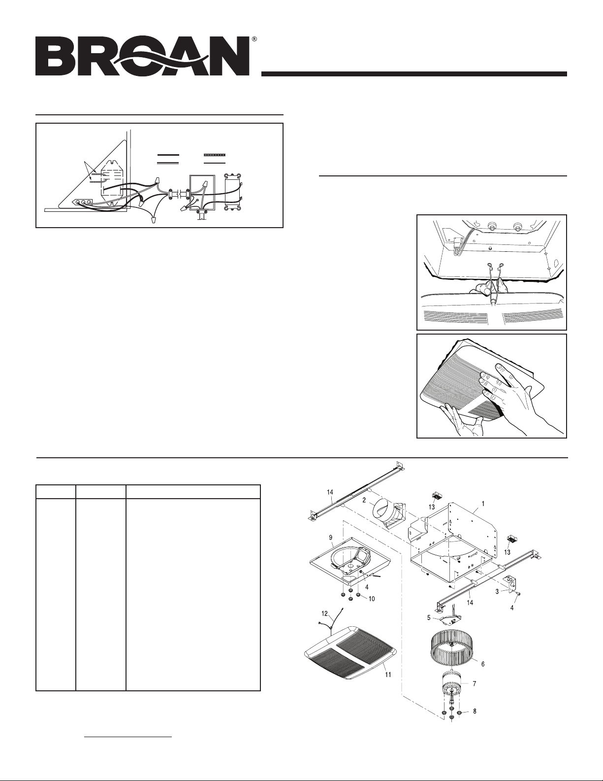
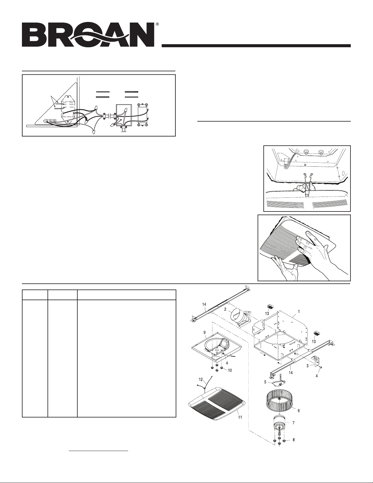
Pour préserver un fonctionnement optimal et silencieux, une
longue durée de vie ainsi qu’une belle apparence, abaisser ou
retirer la grille et passer l’aspirateur à l’intérieur de l’appareil à
l’aide de la brosse à épousseter.
Le moteur est lubrifié à vie. Ne pas huiler. Si les roulements du
moteur sont plus bruyants qu’à l’habitude, remplacer le moteur
par le même moteur de rechange. La roue du ventilateur doit
également être remplacée.
FONCTIONNEMENT
Utiliser un interrupteur Marche/Arrêt (On/Off) ou une
commande de vitesse pour faire fonctionner ce ventilateur. Voir
« Branchement électrique » pour les détails.
BB0001

Page 6
MODÈLES QTR090RC • QTR110RC • QTRE090RC
MONTAGES TYPES
PLANIFICATION
DE L’INSTALLATION
ENTRETROISE
POUR SOLIVE EN «
I
»
PATTES
DE MONTAGE
SOLIVE
EN «
I
»
GRILLE
BOÎTIER
CÂBLE
ÉLECTRIQUE
MATÉRIAU
DE PLAFOND
BH0001F
Boîtier monté sur
des solives en I.
GRILLE
BOÎTIER
MATÉRIAU
DE PLAFOND
C
Â
BLE
ÉLECTRIQUE
PATTES
DE MONTAGE
SOLIVE
DE PLAFOND
BH0003F
Boîtier monté
n’importe où
entre des poutres
triangulées
à l’aide de barres
de suspension.
MATÉRIAU
DE PLAFOND GRILLE
BOÎTIER
BARRES DE SUSPENSION
(s’étirent jusqu’à 24 po)
POUTRE
TRIANGULÉE
CÂBLE
ÉLECTRIQUE
0
05F
C
Â
BLE
ÉLECTRIQUE
GRILLE
SOLIVE
EN «
I
»
BARRES DE SUSPENSION
(s’étirent jusqu’à 24 po)
BOÎTIER
MATÉRIAU
DE PLAFOND
Boîtier monté
n’importe où entre
des solives en I
à l’aide de barres
de suspension.
Boîtier monté sur
des solives.
CÂBLE
ÉLECTRIQUE
BOÎTIER
MATÉRIAU
DE PLAFOND GRILLE
SOLIVE
DE PLAFOND
BARRES DE SUSPENSION
(s’étirent jusqu’à 24 po)
Boîtier monté
n’importe où
entre des solives
à l’aide de barres
de suspension.
Boîtier monté
n’importe où
entre des
poutres
triangulées à
l’aide de barres
de suspension.
MATÉRIAU
DE PLAFOND GRILLE
BOÎTIER
BARRES DE SUSPENSION
(s’étirent jusqu’à 24 po)
POUTRE
TRIANGULÉE
CÂBLE
ÉLECTRIQUE
6F
Pour un fonctionnement optimal et plus silencieux de l’appareil,
utiliser un conduit droit et court et le moins de coudes possible.
Utiliser un capuchon de toit ou de mur avec un clapet intégré
pour réduire les retours d’air.
Prévoir d’alimenter l’appareil avec la tension et le câble
d’alimentation appropriés.
CAPUCHON DE TOIT*
COUDE ROND
DE 4 PO*
CONDUIT
ROND DE
4 PO*
CAPUCHON
DE MUR*
* Vendu
séparément
Cuisinière ou
plaque de cuisson
Plancher
N’installez pas au-dessus
de ce secteur.
45
o
45
o
BH0007F

Page 7
MODÈLES QTR090RC • QTR110RC • QTRE090RC
BJ0002
BJ0001
OU
INSTALLATION DU BOÎTIER
ET DU CONDUIT
1a.Installation
du boîtier à la
solive ou à la
solive en I
Utiliser des pinces
pour plier les
PATTES du boîtier
à 90°. Maintenir le
boîtier en place afin
que les pattes du
boîtier touchent au
bas de la solive. Le
boîtier est installé
à l’aide de quatre
(4) vis ou clous.
Visser ou clouer le
boîtier à la solive
à travers les trous
les plus bas dans
chaque patte de
montage, puis dans
les trous plus haut.
NOTE : L’installation
à la SOLIVE EN I(illustrée ci-contre) requiert l’utilisation
d’ENTRETOISES (incluses) entre les trous les plus hauts
de chaque patte de montage et la solive en I.
1b.Installation du boîtier n’importe où entre des
poutres triangulées, des solives ou des solives
en Ià l’aide des barres de suspension
Des barres de suspension à glissière sont fournies pour
permettre un positionnement du boîtier n’importe où entre
les éléments d’armature. Elles peuvent être utilisées sur
n’importe quel type d’armature (solive en I, solive standard
et poutre triangulée) et peuvent s’étirer jusqu’à 24 po.
Fixer les GLISSIÈRES au boîtier en utilisant les VIS fournies.
S’assurer que les PATTES soient vers le haut tel qu’il est illustré.
Utiliser l’ensemble des trous de montage (marqués STD) pour
fixer le boîtier à ras avec le matériau du plafond. Utiliser l’autre
ensemble de trous pour fixer le boîtier à ras avec le dessus du
matériau de plafond.
SOLIVE EN I
ENTRETOISE (utiliser pour
installer à la solive en I)
BD0001
PATTES
0
002
BARRES DE
SUSPENSION (4)
VIS (4) PATTE
STD
GLISSIÈRE (2)
Étirer les BARRES DE SUSPENSION à la largeur entre
deux poutres.
Maintenir le ventilateur en place à l’aide des pattes des
barres de suspension appuyées sur le rebord inférieur
de l’armature.
CLOUER le ventilateur à l’armature ou le visser (vis non
fournies) dans les TROUS près des clous.
* Pour un fonctionnement silencieux : fixer les barres de
suspension ensemble à l’aide de VIS ou utiliser des pinces
pour bien serrer les glissières sur les barres de suspension.
CLOU (4)
REBORD INFÉRIEUR
DE L’ARMATURE
2. Fixation
du clapet/
raccord de
conduit
Installer le clapet/
raccord de conduit
sur le boîtier.
S’assurer qu’il est
à ras avec le
dessus du boîtier
et que le clapet se
ferme parfaitement.
3. Installation
d’un conduit
rond de 4 po
Fixer un conduit
rond de 4 po au
clapet/raccord de
conduit. Acheminer
le conduit au
capuchon de toit
ou de mur. Sceller
hermétiquement
tous les joints à
l’aide de ruban
à conduits.
TROU POUR VIS DE
MONTAGE OPTIONNELLE (4) *VIS (2)

Page 8
MODÈLES QTR090RC • QTR110RC • QTRE090RC
Repère noPièce noDescription
1 97016466 Boîtier
2 97016449 Raccord de conduit (4 po)
3 98010102 Plaque de branchement
4 99170245 Vis no 8-18 x 0,375 (2 requises)
5 97016736 Panneau de branchement/harnais avec relais
6 99020284 Roue de ventilateur
7 99080577 Moteur (QTR090C)
99080569 Moteur (QTR110C)
99080576 Moteur (QTRE090C)
8 99100491 Amortisseur (4 requis)
9 97016468 Plaque du moteur
10 30260045 Écrou à collet no 8-32 (4 requis)
* 97016733 Bloc ventilateur (QTR090C)
* 97016771 Bloc ventilateur (QTR110C)
* 97016732 Bloc ventilateur (QTRE090C)
(inclut les repères nos 6 à 10)
11 97016497 Ensemble grille (inclut le repère no12)
12 99140199 Ressort de la grille (2 requis)
13 99111293 Entretoise (2 fournies)
14 97016909 Barres de suspension
PIÈCES DE RECHANGE
99043634E
INSTALLATION DE LA GRILLE
6. Fixation de la
grille
au boîtier
Serrer les ressorts de
la grille et les
insérer dans les
fentes de chaque
côté du boîtier.
7. Pousser la
grille contre
le plafond
5. Finition du plafond
Installer le matériau de plafond. Couper autour du boîtier.
O0001
4. Branchement des fils électriques
Avant d’effectuer le branchement de l’appareil, suivre
l’avertissement no2 (page 1).
Retirer le couvercle du compartiment électrique triangulaire
avec relais et la plaque de câblage du boîtier.
À partir de l’interrupteur, passer le fil d’alimentation électrique
120 volts c.a. (avec mise à la terre) à travers la plaque de
câblage jusqu’au compartiment électrique.
Effectuer les branchements suivants à partir de l’alimentation
120 volts c.a. venant de la plaque de câblage (voir le schéma) :
- Brancher le fil NOIR de l’interrupteur au fil NOIR de la
prise à 3 alvéoles et un fil NOIR de l’ensemble relais.
- Brancher le fil BLANC de l’interrupteur au fil BLANC de la prise
à 3 alvéoles et à l’autre fill NOIR de l’ensemble relais.
- Brancher le fil de mise à la terre VERT ou NU de l’interrupteur
au fil de mise à la terre VERT de la prise à 3 alvéoles.
Brancherles2filsBLEUSdescontactsnormalementouverts(N.O.)
du relais au moteur de ventilateur de la fournaise ou au circuit
de commande de la fournaise. Ce branchement effectue la
mise en marche du moteur du ventilateur de la fournaise
BRANCHEMENT ÉLECTRIQUE
BLEU
MISE À LA TERRE (nu)
BLANC
NOIR
ENTRÉE DE LIGNE 120 V c. a.
INTERRUPTEUR
MARCHE / ARRÊT
(acheté
séparément)
FIL BLEU VERS LE
VENTILATEUR
DE LA FOURNAISE
ALIMENTATION ÉLECTRIQUE
AU BOÎTIER D’INTERRUPTEUR
SWITCH BOX
3
5
78
BE0003F
NOTE POUR SERVICE : Pour retirer le bloc ventilateur : Débrancher le moteur (7). Retirer la vis (4) sur le bord de la plaque du moteur (9). Localiser l’unique
PATTE sur la plaque moteur (située à côté de la prise). Pousser vers le haut près de la patte de la plaque du moteur, tout en poussant vers l’extérieur sur le côté du
boîtier, ou insérer un tournevis à lame plate dans la fente du boîtier (à côté de la patte) et faire tourner le tournevis.
Commander les pièces de rechange par node pièce et NON par node repère.
* Illustré non assemblé.
BL0001
PATTE
lorsque le ventilateur fonctionne.
Réinstaller la plaque de câblage et le couvercle de l’ensemble
du compartiment électrique triangulaire avec relais.
Brancher la fiche du moteur à sa prise à 3 alvéoles située
sur le couvercle du compartiment électrique.
Apposer l’étiquette d’avertissement (pièce no990719651)
sur la porte de la fournaise.
This manual suits for next models
4
Table of contents
Languages:
Other Broan Fan manuals

Broan
Broan 353 User manual

Broan
Broan Sensaire MS90 User manual

Broan
Broan 678 User manual

Broan
Broan XB110H User manual

Broan
Broan 741BR Installation instructions

Broan
Broan ERV100S User manual

Broan
Broan NUTONE QT series User manual

Broan
Broan 100HL User manual

Broan
Broan ROOMSIDE AER110LBN Installation guide

Broan
Broan ULTRA SILENT QTXE080 User manual
Popular Fan manuals by other brands

HOFFEN
HOFFEN SF-1283 instruction manual

Ruck Ventilatoren
Ruck Ventilatoren DVA 220 E2 Assembly instruction

Klimawent
Klimawent WP-xxx-D/Ex Series Use and maintenance manual

Hunter
Hunter Valda installation manual

minkaAire
minkaAire Sunseeker instruction manual

STIEBEL ELTRON
STIEBEL ELTRON LWA 252 Operation and installation