manuals.online logo
Brands
  1. Home
  2. •
  3. Brands
  4. •
  5. Broan
  6. •
  7. Fan
  8. •
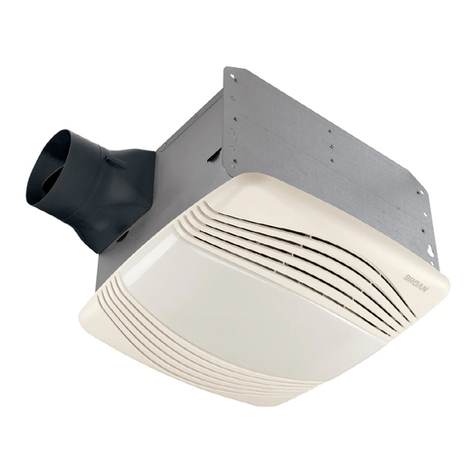
  9. Broan SOLITAIRE ULTRA-SILENT S50U User manual

Broan SOLITAIRE ULTRA-SILENT S50U User manual

This manual suits for next models

4

Other Broan Fan manuals

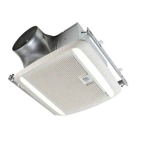
Broan ZB80L1 User manual

Broan

Broan ZB80L1 User manual

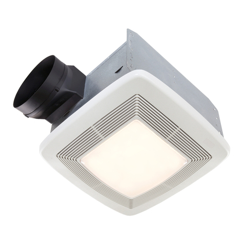
Broan QTRE110FLT User manual

Broan

Broan QTRE110FLT User manual

Broan Losone Select L900 Series User manual

Broan

Broan Losone Select L900 Series User manual

Broan 791LED User manual

Broan

Broan 791LED User manual

Broan ULTRA SILENT QTXE1102 User manual

Broan

Broan ULTRA SILENT QTXE1102 User manual

Broan QTR100FLT User manual

Broan

Broan QTR100FLT User manual

Broan QT140LE User manual

Broan

Broan QT140LE User manual

Broan QTRE100S User manual

Broan

Broan QTRE100S User manual

Broan 673 User manual

Broan

Broan 673 User manual

Broan DX90 User manual

Broan

Broan DX90 User manual

Broan InVent 80 CFM Series Installation guide

Broan

Broan InVent 80 CFM Series Installation guide

Broan 771 User manual

Broan

Broan 771 User manual

Broan NuTone Overture User manual

Broan

Broan NuTone Overture User manual

Broan HFL695 User manual

Broan

Broan HFL695 User manual

Broan 678 User manual

Broan

Broan 678 User manual

Broan QTR080L User manual

Broan

Broan QTR080L User manual

Broan RM326H User manual

Broan

Broan RM326H User manual

Broan QTR090C User manual

Broan

Broan QTR090C User manual

Broan QT DC Series Configuration guide

Broan

Broan QT DC Series Configuration guide

Broan LOSONE SELECT L400L User manual

Broan

Broan LOSONE SELECT L400L User manual

Broan 100HL User manual

Broan

Broan 100HL User manual

Broan ssQTXe080 User manual

Broan

Broan ssQTXe080 User manual

Broan LP110 User manual

Broan

Broan LP110 User manual

Broan LOSONE SELECT L100 User manual

Broan

Broan LOSONE SELECT L100 User manual

Popular Fan manuals by other brands

Minka Group minkaAire Wave F843 instruction manual

Minka Group

Minka Group minkaAire Wave F843 instruction manual

Airflow Adroit DV50 instruction manual

Airflow

Airflow Adroit DV50 instruction manual

Vornado 270 Series owner's guide

Vornado

Vornado 270 Series owner's guide

comfort air TH-10D instruction manual

comfort air

comfort air TH-10D instruction manual

Livoo DOM386 instruction manual

Livoo

Livoo DOM386 instruction manual

Holmes BLIZZARD HAOF-90 owner's guide

Holmes

Holmes BLIZZARD HAOF-90 owner's guide

Taurus GRECO 16 ELEGANCE manual

Taurus

Taurus GRECO 16 ELEGANCE manual

Quorum PINNACLE installation instructions

Quorum

Quorum PINNACLE installation instructions

Monte Carlo Fan Company 3DIR58RBD-V1 Owner's guide and installation manual

Monte Carlo Fan Company

Monte Carlo Fan Company 3DIR58RBD-V1 Owner's guide and installation manual

Craftmade UH52 installation guide

Craftmade

Craftmade UH52 installation guide

Jocel JVA030658 instruction manual

Jocel

Jocel JVA030658 instruction manual

MIKA MFB1211/GR user manual

MIKA

MIKA MFB1211/GR user manual

Harbor Breeze RLG52NWZ5L manual

Harbor Breeze

Harbor Breeze RLG52NWZ5L manual

Allen + Roth L1405 instruction manual

Allen + Roth

Allen + Roth L1405 instruction manual

ViM KUBAIR F400 ECOWATT Technical manual

ViM

ViM KUBAIR F400 ECOWATT Technical manual

HIDRIA R10R-56LPS-ES50B-04C10 user guide

HIDRIA

HIDRIA R10R-56LPS-ES50B-04C10 user guide

BLAUBERG Ventilatoren CENTRO-M 100 L user manual

BLAUBERG Ventilatoren

BLAUBERG Ventilatoren CENTRO-M 100 L user manual

Triangle Engineering HEAT BUSTER SPL Series owner's manual

Triangle Engineering

Triangle Engineering HEAT BUSTER SPL Series owner's manual

manuals.online logo
manuals.online logoBrands
  • About & Mission
  • Contact us
  • Privacy Policy
  • Terms and Conditions

Copyright 2025 Manuals.Online. All Rights Reserved.

99042272G
BROAN ONE YEAR LIMITED WARRANTY
Broan warrants to the original consumer purchaser of its products that such products will be free from defects in materials or workmanship for a period
of one year from the date of original purchase. THERE ARE NO OTHER WARRANTIES, EXPRESS OR IMPLIED, INCLUDING, BUT NOT LIMITED
TO, IMPLIED WARRANTIES OF MERCHANTABILITY OR FITNESS FOR A PARTICULAR PURPOSE.
During this one-year period, Broan will, at its option, repair or replace, without charge, any product or part which is found to be defective under normal
use and service.
THIS WARRANTY DOES NOT EXTEND TO FLUORESCENT LAMP STARTERS AND TUBES.This warranty does not cover (a) normal maintenance
and service or (b) any products or parts which have been subject to misuse, negligence, accident, improper maintenance or repair (other than by
Broan), faulty installation or installation contrary to recommended installation instructions.
The duration of an implied warranty is limited to the one-year period as specified for the express warranty. Some states do not allow limitation on how
long an implied warranty lasts, so the above limitation may not apply to you.
BROAN’S OBLIGATION TO REPAIR OR REPLACE, AT BROAN’S OPTION, SHALL BE THE PURCHASER’S SOLE AND EXCLUSIVE REMEDY
UNDER THIS WARRANTY. BROAN SHALL NOT BE LIABLE FOR INCIDENTAL, CONSEQUENTIAL OR SPECIAL DAMAGES ARISING OUT OF
OR IN CONNECTION WITH PRODUCT USE OR PERFORMANCE. Some states do not allow the exclusion or limitation of incidental or consequen-
tial damages, so the above limitation may not apply to you.
This warranty gives you specific legal rights, and you may also have other rights, which vary from state to state. This warranty supersedes all prior
warranties.
To qualify for warranty service, you must (a) notify Broan at the address stated below or telephone: 1-800-637-1453, (b) give the model number and
part identification and (c) describe the nature of any defect in the product or part. At the time of requesting warranty service, you must present
evidence of the original purchase date.
Broan-NuTone LLC, 926 West State Street, Hartford, WI 53027
KEY PART
NO. NO. DESCRIPTION
1 97013349 Damper/Duct Connector Assembly
2 97013400 Housing Assembly
3 99500389 Insulation — Short
4 98003036 Mounting Bracket (4 Req.)
5 99500388 Insulation — Long
6 93260454 Sheet Metal Nut #8-18*
7 99020270 Impeller — S50U, S80U
99020269 Impeller — S80UE, S110U, S110UE
8 99080454 Motor — S80UE
99080450 Motor — S110U
99080455 Motor — S110UE
9 99080446 Motor — S50U
99080448 Motor — S80U
10 99170245 Screw #8-18 x .375 (2 Req.)*
11 98008868 Knockout Panel
12 99150471 Ground Screw #10-32 x .500*
13 99710033 Spacer (4 Req.)
14 99100483 Grommet (4 Req.)
15 99250254 Washer #8 (4 Req.)*
16 99260425 Nut #8-32 (4 Req.)*
17 97013561 Wire Box Cover Assembly
18 97013401 Venturi Plate Assembly
19 93150459 Screw #8-18 x .500*
20 93140190 Grille Spring (2 Req.)
21 97013402 Grille Assembly (Includes Key No. 20)
22 97013804 Capacitor — S80UE, S110UE
23 99150415 Screw #8-18 x .250*
-- 97013562 Blower Assembly — S50U (Includes Key
Nos. 7, 9, 13, 14, 15, 16, & 18)
-- 97013569 Blower Assembly — S80U (Includes
Key Nos. 7, 9, 13, 14, 15, 16 & 18)
-- 97013564 Blower Assembly — S80UE (Includes
Key Nos. 7, 8, 13, 14, 15, 16, 18, 22 & 23)
-- 97013570 Blower Assembly — S110U (Includes Key
Nos. 7, 8, 13, 14, 15, 16 & 18)
-- 97013571 Blower Assembly — S110UE (Includes
Key Nos. 7, 8, 13, 14, 15, 16, 18,
22 & 23)
* Standard Hardware. May be purchased locally.
Order service parts by "PART NO." — NOT by "KEY NO."
SERVICE PARTS
MODELS S50U, S80U, S80UE, S110U & S110UE
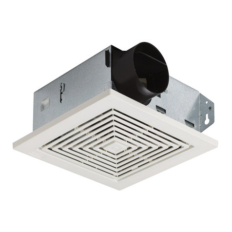
MODELS
S50U, S80U, S80UE,
S110U & S110UE
TYPICAL INSTALLATION
INSTALLER: LEAVE THIS MANUAL WITH THE HOMEOWNER.
HOMEOWNER: USE AND CARE INSTRUCTIONS ON PAGE 3.
SOLITAIRE ULTRA-SILENT®FAN
READ AND SAVE THESE INSTRUCTIONS
WARNING
TO REDUCE THE RISK OF FIRE, ELECTRIC SHOCK, OR INJURY
TO PERSONS, OBSERVE THE FOLLOWING:
1. Use this unit only in the manner intended by the manufacturer. If
you have questions, contact the manufacturer at the address or
telephone number listed in the warranty.
2. Before servicing or cleaning unit, switch power off at service panel
and lock the service disconnecting means to prevent power from
being switched on accidentally. When the service disconnecting
means cannot be locked, securely fasten a prominent warning
device, such as a tag, to the service panel.
3. Installation work and electrical wiring must be done by a qualified
person(s) in accordance with all applicable codes and standards,
including fire-rated construction codes and standards.
4. Sufficient air is needed for proper combustion and exhausting of
gases through the flue (chimney) of fuel burning equipment to
preventbackdrafting.Followtheheatingequipmentmanufacturer’s
guideline and safety standards such as those published by the
National Fire Protection Association (NFPA), and the American
Society for Heating, Refrigeration and Air Conditioning Engineers
(ASHRAE), and the local code authorities.
5. Whencutting or drilling into wall or ceiling, do not damage electrical
wiring and other hidden utilities.
6. Ducted fans must always be vented to the outdoors.
7. If this unit is to be installed over a tub or shower, it must be marked
as appropriate for the application and be connected to a GFCI
(Ground Fault Circuit Interrupter) - protected branch circuit.
8. Never place a switch where it can be reached from a tub or shower.
9. This unit may be used over a tub or shower enclosure when
installed in a GFCI protected branch circuit. (Ceiling Installation
only)
10. This unit must be grounded.
CAUTION
1. For general ventilating use only. Do not use to exhaust hazardous
or explosive materials and vapors.
2. To avoid motor bearing damage and noisy and/or unbalanced
impellers, keep drywall spray, construction dust, etc. off power
unit.
3. Please read specification label on product for further information
and requirements.
HOUSING
MOUNTING
BRACKET
CEILING
JOIST
POWER
CABLE
GRILLE FINISHED CEILING
4" ROUND
DAMPER/DUCT
CONNECTOR
This unit can be installed anywhere between joists using mounting
brackets provided.
The unit can be
installed in a
suspended ceiling
using wire as
shown.
The unit will operate
most quietly when
located where the
shortest possible
duct run and
minimum number of
elbows will be
needed.
Plan to supply the
unit with proper line voltage and appropriate power cable.
Follow these basic steps when installing this unit:
• Nail housing to joists.
• Attach ductwork.
• Connect power cable.
• Install blower assembly.
• Fasten grille to housing.
POWER
CABLE
SUSPENDED CEILING
MATERIAL
4" ROUND DUCT
HOUSING
99042272G
BROAN ONE YEAR LIMITED WARRANTY
Broan warrants to the original consumer purchaser of its products that such products will be free from defects in materials or workmanship for a period
of one year from the date of original purchase. THERE ARE NO OTHER WARRANTIES, EXPRESS OR IMPLIED, INCLUDING, BUT NOT LIMITED
TO, IMPLIED WARRANTIES OF MERCHANTABILITY OR FITNESS FOR A PARTICULAR PURPOSE.
During this one-year period, Broan will, at its option, repair or replace, without charge, any product or part which is found to be defective under normal
use and service.
THIS WARRANTY DOES NOT EXTEND TO FLUORESCENT LAMP STARTERS AND TUBES.This warranty does not cover (a) normal maintenance
and service or (b) any products or parts which have been subject to misuse, negligence, accident, improper maintenance or repair (other than by
Broan), faulty installation or installation contrary to recommended installation instructions.
The duration of an implied warranty is limited to the one-year period as specified for the express warranty. Some states do not allow limitation on how
long an implied warranty lasts, so the above limitation may not apply to you.
BROAN’S OBLIGATION TO REPAIR OR REPLACE, AT BROAN’S OPTION, SHALL BE THE PURCHASER’S SOLE AND EXCLUSIVE REMEDY
UNDER THIS WARRANTY. BROAN SHALL NOT BE LIABLE FOR INCIDENTAL, CONSEQUENTIAL OR SPECIAL DAMAGES ARISING OUT OF
OR IN CONNECTION WITH PRODUCT USE OR PERFORMANCE. Some states do not allow the exclusion or limitation of incidental or consequen-
tial damages, so the above limitation may not apply to you.
This warranty gives you specific legal rights, and you may also have other rights, which vary from state to state. This warranty supersedes all prior
warranties.
To qualify for warranty service, you must (a) notify Broan at the address stated below or telephone: 1-800-637-1453, (b) give the model number and
part identification and (c) describe the nature of any defect in the product or part. At the time of requesting warranty service, you must present
evidence of the original purchase date.
Broan-NuTone LLC, 926 West State Street, Hartford, WI 53027
KEY PART
NO. NO. DESCRIPTION
1 97013349 Damper/Duct Connector Assembly
2 97013400 Housing Assembly
3 99500389 Insulation — Short
4 98003036 Mounting Bracket (4 Req.)
5 99500388 Insulation — Long
6 93260454 Sheet Metal Nut #8-18*
7 99020270 Impeller — S50U, S80U
99020269 Impeller — S80UE, S110U, S110UE
8 99080454 Motor — S80UE
99080450 Motor — S110U
99080455 Motor — S110UE
9 99080446 Motor — S50U
99080448 Motor — S80U
10 99170245 Screw #8-18 x .375 (2 Req.)*
11 98008868 Knockout Panel
12 99150471 Ground Screw #10-32 x .500*
13 99710033 Spacer (4 Req.)
14 99100483 Grommet (4 Req.)
15 99250254 Washer #8 (4 Req.)*
16 99260425 Nut #8-32 (4 Req.)*
17 97013561 Wire Box Cover Assembly
18 97013401 Venturi Plate Assembly
19 93150459 Screw #8-18 x .500*
20 93140190 Grille Spring (2 Req.)
21 97013402 Grille Assembly (Includes Key No. 20)
22 97013804 Capacitor — S80UE, S110UE
23 99150415 Screw #8-18 x .250*
-- 97013562 Blower Assembly — S50U (Includes Key
Nos. 7, 9, 13, 14, 15, 16, & 18)
-- 97013569 Blower Assembly — S80U (Includes
Key Nos. 7, 9, 13, 14, 15, 16 & 18)
-- 97013564 Blower Assembly — S80UE (Includes
Key Nos. 7, 8, 13, 14, 15, 16, 18, 22 & 23)
-- 97013570 Blower Assembly — S110U (Includes Key
Nos. 7, 8, 13, 14, 15, 16 & 18)
-- 97013571 Blower Assembly — S110UE (Includes
Key Nos. 7, 8, 13, 14, 15, 16, 18,
22 & 23)
* Standard Hardware. May be purchased locally.
Order service parts by "PART NO." — NOT by "KEY NO."
SERVICE PARTS
MODELS S50U, S80U, S80UE, S110U & S110UE
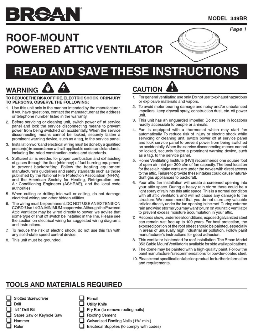
MODELS
S50U, S80U, S80UE,
S110U & S110UE
TYPICAL INSTALLATION
INSTALLER: LEAVE THIS MANUAL WITH THE HOMEOWNER.
HOMEOWNER: USE AND CARE INSTRUCTIONS ON PAGE 3.
SOLITAIRE ULTRA-SILENT®FAN
READ AND SAVE THESE INSTRUCTIONS
WARNING
TO REDUCE THE RISK OF FIRE, ELECTRIC SHOCK, OR INJURY
TO PERSONS, OBSERVE THE FOLLOWING:
1. Use this unit only in the manner intended by the manufacturer. If
you have questions, contact the manufacturer at the address or
telephone number listed in the warranty.
2. Before servicing or cleaning unit, switch power off at service panel
and lock the service disconnecting means to prevent power from
being switched on accidentally. When the service disconnecting
means cannot be locked, securely fasten a prominent warning
device, such as a tag, to the service panel.
3. Installation work and electrical wiring must be done by a qualified
person(s) in accordance with all applicable codes and standards,
including fire-rated construction codes and standards.
4. Sufficient air is needed for proper combustion and exhausting of
gases through the flue (chimney) of fuel burning equipment to
preventbackdrafting. Follow the heating equipmentmanufacturer’s
guideline and safety standards such as those published by the
National Fire Protection Association (NFPA), and the American
Society for Heating, Refrigeration and Air Conditioning Engineers
(ASHRAE), and the local code authorities.
5. Whencutting or drilling into wall or ceiling, do not damage electrical
wiring and other hidden utilities.
6. Ducted fans must always be vented to the outdoors.
7. If this unit is to be installed over a tub or shower, it must be marked
as appropriate for the application and be connected to a GFCI
(Ground Fault Circuit Interrupter) - protected branch circuit.
8. Never place a switch where it can be reached from a tub or shower.
9. This unit may be used over a tub or shower enclosure when
installed in a GFCI protected branch circuit. (Ceiling Installation
only)
10. This unit must be grounded.
CAUTION
1. For general ventilating use only. Do not use to exhaust hazardous
or explosive materials and vapors.
2. To avoid motor bearing damage and noisy and/or unbalanced
impellers, keep drywall spray, construction dust, etc. off power
unit.
3. Please read specification label on product for further information
and requirements.
HOUSING
MOUNTING
BRACKET
CEILING
JOIST
POWER
CABLE
GRILLE FINISHED CEILING
4" ROUND
DAMPER/DUCT
CONNECTOR
This unit can be installed anywhere between joists using mounting
brackets provided.
The unit can be
installed in a
suspended ceiling
using wire as
shown.
The unit will operate
most quietly when
located where the
shortest possible
duct run and
minimum number of
elbows will be
needed.
Plan to supply the
unit with proper line voltage and appropriate power cable.
Follow these basic steps when installing this unit:
• Nail housing to joists.
• Attach ductwork.
• Connect power cable.
• Install blower assembly.
• Fasten grille to housing.
POWER
CABLE
SUSPENDED CEILING
MATERIAL
4" ROUND DUCT
HOUSING