Broan QTX110HL User manual

Page 1
MODEL QTX110HL
WARNING
TO REDUCE THE RISK OF FIRE, ELECTRIC SHOCK, OR IN-
JURY TO PERSONS, OBSERVE THE FOLLOWING:
1. Use this unit only in the manner intended by the manufac-
turer. If you have questions, contact the manufacturer at the
address or telephone number listed in the warranty.
2. Before servicing or cleaning unit, switch power off at service
panel and lock the service disconnecting means to prevent
power from being switched on accidentally. When the ser-
vice disconnecting means cannot be locked, securely fasten
a prominent warning device, such as a tag, to the service
panel.
3. Installation work and electrical wiring must be done by a
qualified person(s) in accordance with all applicable codes
and standards, including fire-rated construction codes and
standards.
4. Sufficient air is needed for proper combustion and exhaust-
ing of gases through the flue (chimney) of fuel burning equip-
ment to prevent backdrafting. Follow the heating equipment
manufacturer’s guideline and safety standards such as those
published by the National Fire Protection Association (NFPA),
and the American Society for Heating, Refrigeration and Air
Conditioning Engineers (ASHRAE), and the local code au-
thorities.
5. When cutting or drilling into wall or ceiling, do not damage
electrical wiring and other hidden utilities.
6. Ducted fans must always be vented to the outdoors.
7. Provide a separate 20 AMP circuit. Use 12 GA. power cable
of type which meets code.
8. This unit must be grounded.
CAUTION
!
1. For general ventilating use only. Do not use to exhaust haz-
ardous or explosive materials and vapors.
2. This product is designed for installation in ceilings up to a
12/12 pitch. Duct connector must point up. DO NOT MOUNT
THIS PRODUCT IN A WALL.
3. To avoid motor bearing damage and noisy and/or unbal-
anced impellers, keep drywall spray, construction dust, etc.
off power unit.
4. Please read specification label on product for further infor-
mation and requirements.
QTX SERIES
HEATER / FAN / LIGHT /
NIGHT LIGHT
READ AND SAVE THESE INSTRUCTIONS
CLEANING & MAINTENANCE
WARRANTY
BROAN-NUTONE THREE YEAR LIMITED WARRANTY
Broan-NuTone warrants to the original consumer purchaser of its products that such
products will be free from defects in materials or workmanship for a period of three years
from the date of original purchase. THEREARE NO OTHER WARRANTIES, EXPRESS OR
IMPLIED, INCLUDING, BUT NOT LIMITED TO, IMPLIED WARRANTIES OF MERCHANT-
ABILITY OR FITNESS FORAPARTICULAR PURPOSE.
During this three-year period, Broan-NuTone will, at its option, repair or replace, without
charge, any product or part which is found to be defective under normal use and service.
THIS WARRANTY DOES NOT EXTEND TO FLUORESCENT LAMPSTARTERSANDTUBES.
This warranty does not cover (a) normal maintenance and service or (b) any products
or parts which have been subject to misuse, negligence, accident, improper mainte-
nance or repair (other than by Broan-NuTone), faulty installation or installation contrary
to recommended installation instructions.
The duration of an implied warranty is limited to the three-year period as specified for
the express warranty. Some states do not allow limitation on how long an implied war-
ranty lasts, so the above limitation may not apply to you.
BROAN-NUTONE’S OBLIGATION TO REPAIR OR REPLACE, AT BROAN-NUTONE’S OP-
TION, SHALL BE THE PURCHASER’S SOLEAND EXCLUSIVE REMEDY UNDER THIS
WARRANTY. BROAN-NUTONE SHALL NOT BE LIABLE FOR INCIDENTAL, CONSEQUEN-
TIAL OR SPECIALDAMAGESARISING OUT OF OR IN CONNECTION WITH PRODUCT
USE OR PERFORMANCE. Some states do not allow the exclusion or limitation of inciden-
tal or consequential damages, so the above limitation may not apply to you.
This warranty gives you specific legal rights, and you may also have other rights, which
vary from state to state. This warranty supersedes all prior warranties.
To qualify for warranty service, you must (a) notify Broan-NuTone at the address or
telephone number stated below, (b) give the model number and part identification and
(c) describe the nature of any defect in the product or part. At the time of requesting
warranty service, you must present evidence of the original purchase date.
Broan-NuTone LLC, 926 West State Street, Hartford, WI 53027
(1-800-637-1453)
Installer: Leave this manual with the homeowner.
For quiet and efficient operation, long life, and attractive ap-
pearance - lower or remove grille and vacuum interior of unit
with the dusting brush attachment.
The motor is permanently lubricated and never needs oiling. If
the motor bearings are making excessive or unusual noises,
replace the motor with the exact service motor. The impeller
should also be replaced.
Replace light bulbs with (2) 60-Watt (maximum) incandescent
light bulbs and (1) 7-Watt night light bulb.
OPERATION
Use a 4-Function Control to operate the heater, fan, light, and
night light separately. See “Connect Wiring” for details.
NOTE: This unit is designed with a thermostat which senses
excess heat and may start the blower automatically. This is
normal and is no cause for concern.
NOTE: Fan may cycle when light is on. Blinking light may indi-
cate improper lamp wattage or type.

Page 2
MODEL QTX110HL
TYPICAL INSTALLATION
HOUSING
CEILING
JOIST, TRUSS,
OR I-JOISTS
MOUNTING
CHANNELS
GRILLE
CEILING
MATERIAL
POWER
CABLES
Housing mounted directly to joists, trusses, or I-joists.
Up to 24-inches on-center.
Unit shown connected to 6-inch round ductwork.
ROOF CAP *
6-IN. ROUND
ELBOW *
6-IN. ROUND
DUCT *
WALL
CAP *
*Purchase separately
PLAN THE INSTALLATION
The unit will operate most quietly and efficiently when located
where the shortest possible duct run and minimum number of
elbows will be needed.
Plan to supply the unit with proper line voltage and appropriate
power cable.
INSTALLATION
2. Mount
housing.
Secure housing
to ceiling
structure with (4)
mounting screws.
Make sure
bottom of
housing will be
flush with
finished ceiling
material.
1. Insert
mounting
brackets.
Slide the (4)
mounting
brackets into the
channels on
each end of the
housing.
3. Attach
damper /
duct
connector
to housing.
Snap damper /
duct connector
onto housing.
Make sure
connector is
flush with top of
housing and damper flap falls closed.
4. Install 6-
inch round
ductwork.
Connect 6-inch
round ductwork
to damper / duct
connector. Run
ductwork to a
roof cap or wall
cap. Tape all
ductwork
connections to
make them secure and air tight.

Page 3
MODEL QTX110HL
8. Plug-in light.
Hold grille
assembly up
near housing.
Connect light
plug from grille
assembly to
receptacle inside
of housing.
INSTALL GRILLE & BULBS
9. Attach
grille.
Remove the (2)
grille mounting
screws from the
sides of the
housing. (See
Step 8 illustra-
tion.) Use these
screws to attach
the grille to the
housing as
shown.
To avoid damage to the grille: DO NOT OVERTIGHTEN
SCREWS. Tighten screws only until grille is snug against
ceiling material.
10. Install
bulbs.
The unit
accepts (2) 60-
Watt (maxi-
mum) incan-
descent bulbs
and (1) 7-Watt
night light bulb.
11. Attach
light lens.
Hook the tabs
on one end of
the lens into the
slot in the grille.
Lift other end of
lens up and
snap into place.
GRILLE MOUNTING
SCREWS
5. Connect electrical wiring.
Run 120 VAC house wiring to installation location. Use
proper UL approved connectors to secure house wiring to
wiring plate. Connect wires as shown in wiring
diagram(s).
CONNECT WIRING
INSTALL GRILLE & BULBS
7. Remove
light lens
from grille.
Insert a small flat-
bladed screw-
driver into the slot
at one end of the
light lens.
Carefully pry the
lens out.
6. Finish ceiling.
Install ceiling material. Cut out ceiling material closely
around housing.
WHITE
to
WHITE
HEAT (2-position rocker)
LIGHT (red)
NIGHT LIGHT (blue)
(3-position rocker)
4-FUNCTION CONTROL
GROUND
120 VAC LINE IN
BLACK to BLUE
BLACK to RED
BLACK to BLACKS
FAN (2-position rocker)
RED
RED
WIRING PLATE
FROM VENTILATOR
VENTILATOR
HOUSING
LIGHT
&
FAN
HEAT
&
NIGHT LIGHT
BLACK to BLUE
(Light)
WHITE to WHITE
RED to RED
(Fan)
RED to BLACK
(Heat)
BLACK to YELLOW
(Night Light)
WHITE to WHITE
CAUTION
RATINGSPECIFICATIONS
• The three-position
rocker switch is rated 5A
@ 125VAC. Use this switch
for Lights ONLY.
• Each two-position rocker
switch is rated 15 A @ 120VAC. Use these switches for Heat and Vent.
• The total load on this control must not exceed 20A @ 120VAC.
Broan 4-Function
Control shown
(purchase separately)

Page 4
MODEL QTX110HL
SERVICE PARTS
Key No. Part No. Description
1 97016470 Housing
2 98007763 Slide Channel (2 req.)
3 98003036 Support Angle (4 req.)
4 97016450 Duct Connector
5 99170245 Screw #8-18 X .375 (8 req.)
6 93260454 Nut, Sheet Metal #8-18 (Partition)
(2 req.)
7 99260512 Nut, Sheet Metal #8-18 (Grille)
(3 req.)
8 98010091 Cover/KO Panel
9 99150471 Screw, Ground (2 req.)
10 97016563 Wire Panel/Harness Assembly
11 98010090 Wire Compartment
12 98010089 Mounting Bracket-Heater
13 99150415 Screw #8-18 X .250 (4 req.)
14 99260488 Nut, Hex #10-24 (5 req.)
15 97016564 Heater Scroll
16 99020283 Wheel-Heater
17 99260423 Nut, Hex #8-32 (4 req.)
18 98010088 Motor Mount
19 99080558 Motor-Heater
20 97016565 Heating Element
(includes Key No. 7)
97016566 Heater Scroll Assembly
(includes Key Nos. 12 thru 20)
21 99020284 Wheel-Fan
22 99080556 Motor-Fan
23 99100491 Isolator (4 req.)
24 97016471 Partition
25 99250959 Washer (4 req.)
26 99260558 Nut, Hex Lock #8-32 (4 req.)
97016567 Blower Assembly
(includes Key Nos. 21 thru 26)
27 93150459 Screw #8-18 X .500 (2 req.)
28 97016474 Grille Assembly
(includes Key No. 29)
29 99111291 Lens
30 99150622 Screw, Grille #8-18 X 2.000 (2 req.)
58
2
3
1
9
5
7
7
2
4
10
5
5
11
14
19
18
20
13
17
16
15
12
13
14
21
22
23
24
25
26
30
6
7
29
28
27
3
99043413G

Página 5
MODELO QTX110HL
ADVERTENCIA
PARA REDUCIR EL RIESGO DE INCENDIOS, DESCARGAS
ELÉCTRICAS O LESIONES PERSONALES, OBSERVE LAS
SIGUIENTES PRECAUCIONES:
1. Use la unidad sólo de la manera indicada por el fabricante.
Si tiene preguntas, comuníquese con el fabricante a la dirección
o al número telefónico que se incluye en la garantía.
2. Antes de dar servicio a la unidad o de limpiarla, interrumpa el
suministro eléctrico en el panel de servicio y bloquee los medios
de desconexión del servicio para evitar que la electricidad se
reanude accidentalmente. Cuando no sea posible bloquear los
medios de desconexión del servicio, fije firmemente en un lugar
prominente del panel de servicio un dispositivo de advertencia,
como por ejemplo una etiqueta.
3. Una o más personas calificadas deben realizar el trabajo de
instalación y el cableado eléctrico, de acuerdo con todos los
códigos y normas correspondientes, incluidos los códigos y
normas de construcción específicos de protección contra
incendios.
4. Se necesita suficiente aire para que se lleve a cabo la combustión
y descarga adecuadas de los gases a través del tubo de humos
(chimenea) del equipo quemador de combustible, con el fin de
evitar los contratiros. Siga las directrices y normas de seguridad
del fabricante del equipo de calefacción, tales como las publicadas
por la Asociación Nacional de Protección contra Incendios (Na-
tional Fire Protection Association, NFPA), la Sociedad Americana
de Ingenieros de Calefacción, Refrigeración y Aire Acondicionado
(American Society for Heating, Refrigeration and Air Conditioning
Engineers, ASHRAE) y las autoridades de los códigos locales.
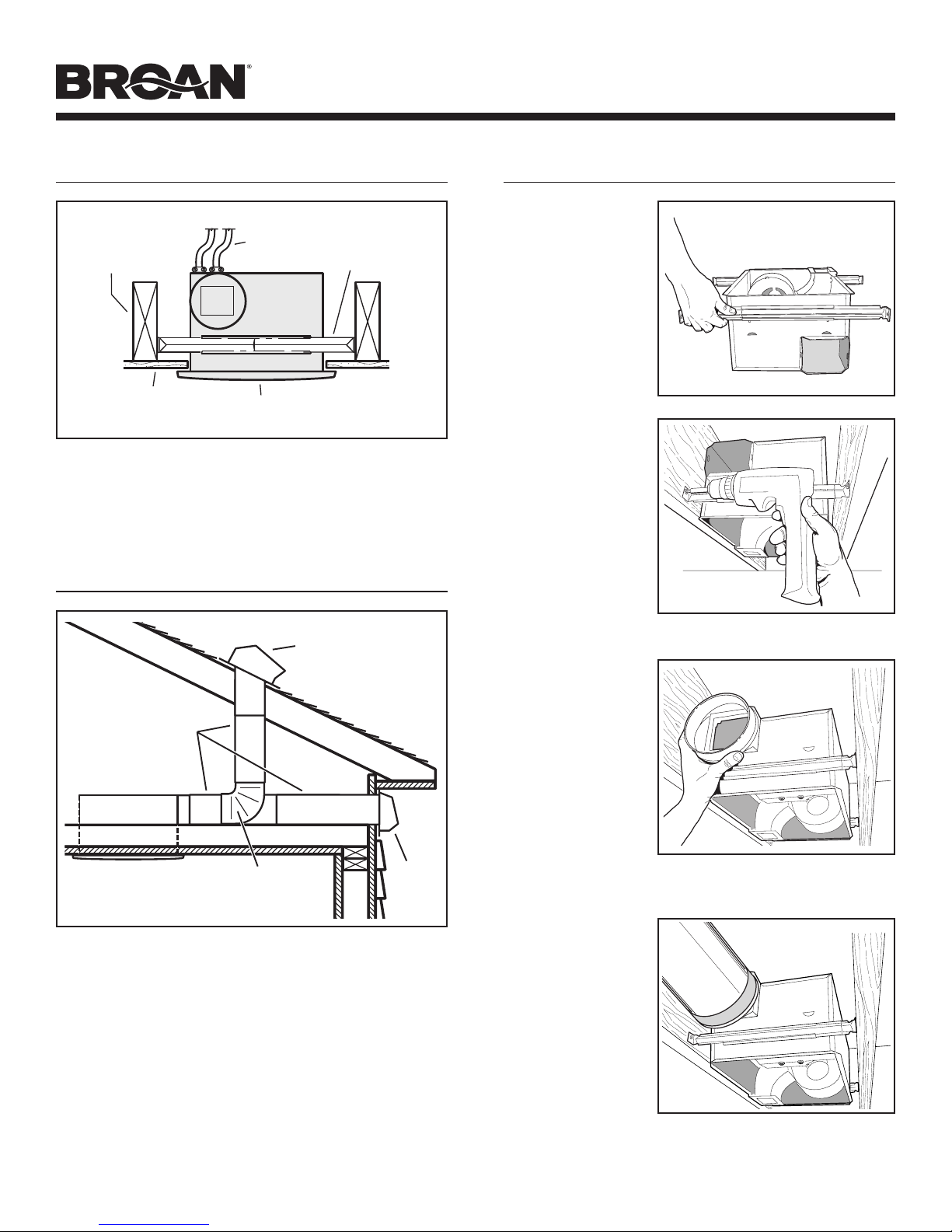
5. Al cortar o perforar a través de la pared o del cielo raso, no dañe
el cableado eléctrico ni otros servicios ocultos.
6. Los ventiladores con conductos siempre se deben conectar hacia
el exterior.
7. Provea un circuito por separado de 20 AMP. Use un cable de
potencia 12 GA. del tipo conforme al código.
8. Esta unidad se debe conectar a tierra.
PRECAUCIÓN
!
1. Sólo para usarse en ventilación general. No se use para descargar
materiales ni vapores peligrosos o explosivos.
2. Este producto se diseña para la instalación en techos hasta una
echada de 12/12. Conector de conductor debe señalar hacia arriba.
NO MONTE ESTE PRODUCTO EN UNA TECHO.
3. Para evitar daños a los cojinetes del motor y rotores ruidosos y/o no
equilibrados, mantenga la unidad de accionamiento al resguardo de
rociados de yeso, polvos de construcción, etc.
4. Lea la etiqueta de especificaciones del producto para ver información
y requisitos adicionales.
SERIE QTX
CALEFACTOR / VENTILADOR /
LUZ / LUZ DE NOCHE
LEA Y CONSERVE ESTAS INSTRUCCIONES
LIMPIEZA Y MANTENIMIENTO
GARANTIA
A la persona que realiza la instalación: Deje este manual con el dueño de la casa.
Para obtener una operación silenciosa y eficiente, una larga vida y una
apariencia atractiva, baje o retire la rejilla y aspire el interior de la unidad
con el accesorio del cepillo para sacudir polvo.
El motor está permanentemente lubricado y nunca necesitará aceite. Si
los cojinetes del motor están haciendo ruido excesivo o inusual,
reemplace el motor con el motor de servicio exacto. El impulsor también
debe ser reemplazado.
Reemplace los focos con dos (2) focos incandescentes de 60 watts
(máximo) y un (1) foco de luz nocturna de 7 watts.
OPERACIÓN
GARANTIA BROAN-NUTONE LIMITADA POR TRESAÑOS
Broan-NuTone garantiza al consumidor comprador original de sus productos que dichos productos
carecerán de defectos en materiales o en mano de obra por un período de tres años a partir de la fecha
original de compra. NO EXISTEN OTRAS GARANTIAS, EXPLICITAS O IMPLICITAS, INCLUYENDO,
PERO NO LIMITADASA, GARANTIAS IMPLICITAS DE COMERCIALIZACION OAPTITUD PARAUN
PROPOSITO PARTICULAR.
Durante el período de tres años, y a su propio criterio, Broan-NuTone reparará o reemplazará, sin costo
alguno cualquier producto o pieza que se encuentre defectuosa bajo condiciones normales de servicio
y uso.
ESTA GARANTIANO SEAPLICAATUBOS YARRANCADORES DE LAMPARAS FLUORESCENTES.
Esta garantía no cubre (a) mantenimiento y servicio normales o (b) cualquier producto o piezas que
hayan sido utilizadas de forma errónea, negligente, que hayan causado un accidente, o que hayan sido
reparadaso mantenidas inapropiadamente(por otras compañíasque no seanBroan-NuTone),instalación
defectuosa, o instalación contraria a las instrucciones de instalación recomendadas.
La duración de cualquier garantía implícita se limita a un período de tres años como se especifica en
la garantía expresa. Algunos estados no permiten limitaciones en cuanto al tiempo de expiración de
una garantía implícita, por lo que la limitación antes mencionada puede no aplicarse a usted.
LAOBLIGACION DE BROAN-NUTONE DE REPARAR O REEMPLAZAR, SIGUIENDO EL CRITERIO
DEBROAN-NUTONE,DEBERA SER EL UNICO Y EXCLUSIVORECURSOLEGALDEL COMPRADOR
BAJOESTAGARANTIA. BROAN-NUTONENO SERARESPONSABLEPOR DAÑOS INCIDENTALES,
CONSIGUIENTES, O POR DAÑOS ESPECIALES QUE SURJAN A RAIZ DEL USO O DESEMPEÑO
DEL PRODUCTO. Algunos estados no permiten la exclusión o limitación de daños incidentales o
consiguientes, por lo que la limitación antes mencionada puede no aplicarse a usted.
Esta garantía le proporciona derechos legales específicos, y usted puede también tener otros derechos,
los cuales varían de estado a estado. Esta garantía reemplaza todas las garantías anteriores.
Para calificar en la garantía de servicio, usted debe (a) notificar a Broan-NuTone al domicilio o al número
de teléfono abajo, (b) dar el número del modelo y la identificación de la pieza, y (c) describir la naturaleza
de cualquier defecto en el producto o pieza. En el momento de solicitar servicio cubierto por la garantía,
usted debe de presentar evidencia de la fecha original de compra.
Broan-NuTone LLC, 926 West State Street, Hartford, WI 53027 (1-800-637-1453)
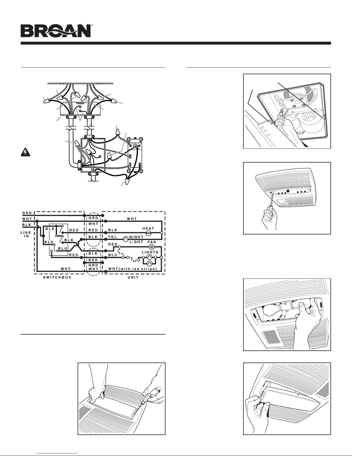
Utilice un control de 4 funciones para operar el calefactor, el ventilador,
la luz y la luz nocturna por separado. Vea los detalles en "Conexión
eléctrica".
NOTA: Esta unidad ha sido diseñada con un termostato que detecta los
excesos de calor y puede encender el soplador automáticamente. Esto
es normal y no debe ser motivo de preocupación.
NOTA: El ventilador puede completar un ciclo por intervalos cuando la
luz está encendido. La luz del intermitente puede indicar vatiaje o el tipo
incorrecto de la lámpara.

Página 6
MODELO QTX110HL
INSTALACIÓN TÍPICA
CUBIERTA
RANURAS
DE MONTAJE
REJILLA
VIGA DE TECHO,
TIRANTE O
VIGA EN I
MATERIAL DEL
CIELO RASO
CABLES DE
ELECTRICIDAD
La cubierta se monta directamente sobre las
vigas, tirantes o vigas en I.
Hasta 24 pulgadas en centro.
La unidad ilustrada está conectada a un conducto
redondo de 6 pulg.
TAPA DE TECHO *
CODO
REDONDO DE
6 PULG. *
CONDUCTO
REDONDO DE
6 PULG. *
TAPA
DE
PARED *
*Se compran por separado
PLANIFICACIÓN DE LA
INSTALACIÓN
El ventilador funcionará con más eficiencia y menos ruido si se
ubica en un sitio donde requiera el tramo de conducto más corto
posible y un mínimo número de codos.
Alimente la unidad con el voltaje de línea y el cable eléctrico
apropiados.
INSTALACIÓN
2. Monte la
cubierta.
Fije la cubierta a la
estructura del cielo
raso con cuatro (4)
tornillos de
montaje.
Asegúrese de que
la parte inferior de
la cubierta esté a
nivel con el
material terminado
del cielo raso.
1. Inserte los
soportes de
montaje.
Deslice los (4)
soportes de
montaje en las
ranuras en cada
extremo de la
cubierta.
3. Acople el
conector del
regulador
de tiro/
conducto a
la cubierta.
Conecte a presión
el conector del
regulador de tiro/
conducto en la
cubierta.
Asegúrese de que el conector esté al ras con la parte superior
de la cubierta y que la aleta del regulador caiga cerrada.
4. Instale el
conducto
redondo de
6 pulg.
Conecte el
conducto redondo
de 6 pulg. al
conector del
regulador /
conducto.
Extienda el
conducto hacia
una tapa de techo o tapa de pared. Encinte todas las
conexiones de los conductos para fijarlas y hacerlas
herméticas al aire.

Página 7
MODELO QTX110HL
8. Conecte el
foco.
Sostenga el
conjunto de la
rejilla cerca de la
cubierta. Conecte
el foco del
conjunto de la
rejilla al
receptáculo dentro
de la cubierta.
INSTALE LA REJILLA Y LOS
FOCOS
9. Fije la
rejilla.
Quite los dos (2)
tornillos de
montaje de la
rejilla de los lados
de la cubierta.
(Vea la ilustración
de paso 8.) Utilice
estos tornillos
para fijar la rejilla
a la cubierta, tal
como se muestra.
Para evitar daños en la rejilla: NO APRIETE DE MÁS LOS
TORNILLOS. Apriete los tornillos hasta que la rejilla esté
firmemente ceñida contra el material del cielo raso.
10. Instale los
focos.
La unidad acepta
dos (2) focos
incandescentes
de 60 watts
(máximo) y un (1)
foco de luz
nocturna de
7 watts.
11. Fije la lente
de la luz.
Enganche las
lengüetas por un
extremo de la
lente en la ranura
de la rejilla.
Levante el otro
extremo de la
lente y fíjela en su
lugar.
TORNILLOS DE MONTAJE
DE LA REJILLA
5. Conecte los cables eléctricos.
Extienda el cableado de la casa de 120 VCA al lugar de la
instalación. Utilice conexiones aprobadas por UL para asegurar
el cableado de la casa a la placa de cableado. Conecte los
cables tal como se ilustra en los diagramas de cableado.
CONEXIÓN ELÉCTRICA
INSTALE LA REJILLAY LOS FOCOS
7. Quite la lente
del foco de la
rejilla.
Inserte un pequeño
destornillador plano
en la rejilla en un
extremo de la lente
del foco. Haga
palanca con
cuidado para retirar
la lente.
6. Termine el cielo raso.
Instale el material del cielo raso. Recorte el material del cielo
raso de cerca alrededor de la cubierta.
BLANCO
a
BLANCO
CALENTADOR
(interruptor 2-posición)
LUZ (rojo)
LUZ DE NOCHE (azul)
(3-position rocker)
CONTROL DE
4 FUNCIONNES
TIERRA
LINEA DE ENTRADA
120 VCA
NEGRO a AZUL
NEGRO a ROJO
NEGRO a NEGROS
VENTILADOR
(interruptor 2-posición)
ROJO
ROJO
PLACA DE CABLE
DE VENTILADOR
CAJA DEL VENTILADOR
LUZ
Y
VENTILADOR
CALENTADOR
Y
LUZ DE NOCHE
NEGRO a AZUL
(Luz)
ROJO a ROJO
(Ventilador)
ROJO a NEGRO
(Calentador)
NEGRO a AMARILLO
(Luz de noche)
BLANCO a BLANCO BLANCO a BLANCO
CUIDADO
ESPECIFICACIONES
DEL GRADO
• Elinterruptor de ejede
balancíndetresposiciones
esclasificado5A@
125VCA.Utiliceeste
interruptorpara las lucesSOLAMENTE.
•
Elinterruptor deejedebalancín dedosposiciones esclasificado15A
@120VCA. Utilice estos interruptoresparaelcalor y elventilador.
•
Lacarga total enestecontrol no debeexcederse20A@ 120VCA.
Broan control para
4-funciones ilustrado
(comprar separado)

Página 8
MODELO QTX110HL
PIEZAS DE REPUESTO
Clave No.
Pieza No. Descripción
1 97016470 Cubierta
2 98007763 Ranura de deslizamiento
(se req. 2)
3 98003036 Ángulo de soporte (se req. 4)
4 97016450 Conector del conducto
5 99170245 Tornillo, #8-18 x 0.375 (se req. 8)
6 93260454 Tuerca de chapa #8-18 (División)
(se req. 2)
7 99260512 Tuerca de chapa #8-18 (Rejilla)
(se req. 3)
8 98010091 Cubierta/ Panel KO
9 99150471 Tornillo de conexión a tierra
(se req. 2)
10 97016563 Conjunto del panel de
cableado/arnés
11 98010090 Compartimiento de cables
12 98010089 Soporte de montaje-Calefactor
13 99150415 Tornillo, #8-18 x 0.250 (se req. 4)
14 99260488 Tuerca hexagonal #10-24
(se req. 5)
15 97016564 Desplazador del calefactor
16 99020283 Disco-Calefactor
17 99260423 Tuerca hexagonal #8-32
(se req. 4)
18 98010088 Montaje del motor
19 99080558 Motor-Calefactor
20 97016565 Elemento de calefacción
(incluye clave no. 7)
97016566 Conjunto del desplazador del
calefactor (incluye clave nos.
12 á 20)
21 99020284 Disco-Ventilador
22 99080556 Motor-Ventilador
23 99100491 Aislante (se req. 4)
24 97016471 División
25 99250959 Arandela (se req. 4)
26 99260558 Tuerca hexagonal de
seguridad #8-32 (se req. 4)
97016567 Conjunto del ventilador
(incluye clave nos. 21 á 26)
27 93150459 Tornillo, #8-18 x 0.500 (se req. 2)
28 97016474 Conjunto de la rejilla
(incluye clave no. 29)
29 99111291 Lentes
30 99150622
Tornillo de la rejilla, #8-18 x 2.000
(se req. 2)
99043413G
58
2
3
1
9
5
7
7
2
4
10
5
5
11
14
19
18
20
13
17
16
15
12
13
14
21
22
23
24
25
26
30
6
7
29
28
27
3
Other manuals for QTX110HL
4
Table of contents
Languages:
Other Broan Heater manuals
Popular Heater manuals by other brands

cecotec
cecotec READYWARM 2070 MAX CERAMIC ROTATE SMART instruction manual

Alpina
Alpina LQ003 instruction manual

Consort
Consort PLSTi Series Installation & Control Guide

Harvia
Harvia K10G-U1 owner's manual

Dru
Dru Metro 80E Installation and service manual

Ridea
Ridea Living Othello Mono Slim Instruction and installation booklet

Cairox
Cairox SOLANO CEILING-W-100 Technical documentation

SAMUEL JACKSON
SAMUEL JACKSON Vulcain Service manual

EQUATION
EQUATION YD02-5 Safety instructions

Flagro
Flagro FLE-60CSA Installation and maintenance manual

HSS Hire
HSS Hire 56282 Operating & safety guide

Remington
Remington REM-03-240-GH User's manual and operating instructions