Página 9
MODELO 744LED
ADVERTENCIA
PARA REDUCIR EL RIESGO DE INCENDIOS, DESCARGAS
ELÉCTRICAS O LESIONES PERSONALES, SIGA LAS
SIGUIENTES PRECAUCIONES:
1. Use la unidad solo de la manera indicada por el fabricante.
Sitiene preguntas, comuníquese con el fabricante a la dirección
o al número telefónico que se incluye en la garantía.
2. Antes de dar servicio a la unidad o de limpiarla, interrumpa el
suministro eléctrico en el panel de servicio y bloquee los medios de
desconexión del servicio para evitar que la electricidad se reanude
accidentalmente. Cuando no sea posible bloquear los medios de
desconexión del servicio, fije firmemente una señal de advertencia
(como una etiqueta) en un lugar visible del panel de servicio.
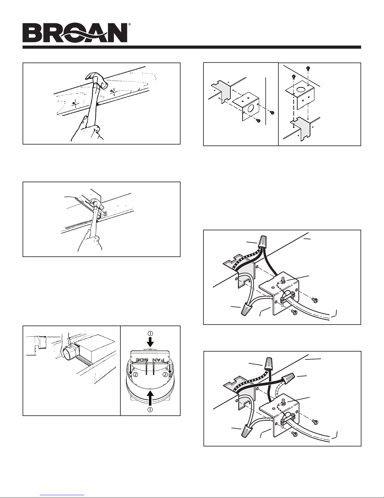
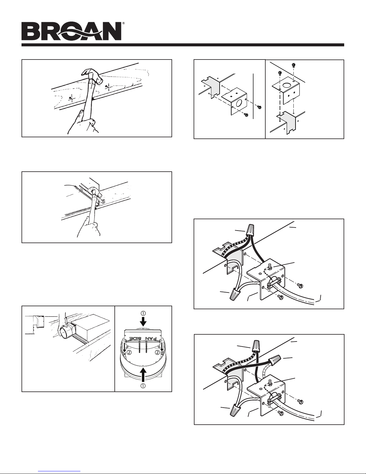
3. El trabajo de instalación y el cableado eléctrico deben estar a
cargo de personal capacitado, de acuerdo con todos los códigos
y normas correspondientes, incluidos los códigos y normas de
construcción específicos sobre protección contra incendios.
4. Es necesario suficiente aire para que se lleve a cabo una
combustión y una extracción adecuadas de los gases a
través del tubo de humos (chimenea) del equipo quemador
de combustible, con el fin de evitar el contratiro. Siga las
directrices y las normas de seguridad del fabricante del equipo
decalefacción, comolas publicadas por laAsociación Nacional de
Protección contra Incendios (National Fire Protection Association,
NFPA), laSociedad Americana de Ingenieros de Calefacción,
Refrigeración yAireAcondicionado (American Society for Heating,
Refrigeration and Air Conditioning Engineers, ASHRAE) y las
autoridades normativas locales.
5. Al cortar o perforar a través de la pared o del techo, tenga cuidado
de no dañar el cableado eléctrico ni otros servicios ocultos.
6. Los ventiladores con conductos siempre deben ventearse hacia
el exterior.
7. Nunca coloque el interruptor en un lugar en donde se pueda
alcanzar desde la bañera o ducha.
8. Se puede utilizar un reductor de intensidad a fin de hacer funcionar
la lámpara en esta unidad. Consulte la lista de reductores de
intensidad compatibles en broan.com.
9. Instale esta unidad únicamente en un techo plano.
10. Para usarse únicamente en instalaciones sin clasificación
contraincendios.
11. No se debe usar en espacios que manejen aire ambiental.
12. Si se va a instalar esta unidad sobre una tina o ducha, debe estar
marcada como apropiada para esta aplicación y conectarse a
unGFCI (interruptor accionado por pérdida de conexión a tierra)
enun circuito de derivación protegido.
13. No se debe instalar en un techo que tenga un valor de aislamiento
térmico superior a R60.
14. Esta unidad debe estar conectada a tierra.
PRECAUCIÓN
1. Solo para usarse como medio de ventilación general.No debe usarse
para la extracción de materiales o vapores peligrosos o explosivos.
2. Para evitar daños a los cojinetes del motor y rotores ruidosos o
desbalanceados, use el protector de cartón (incluido) para mantener
alejados de la unidad de accionamiento el rocío de yeso, el polvo
de la construcción, etc.
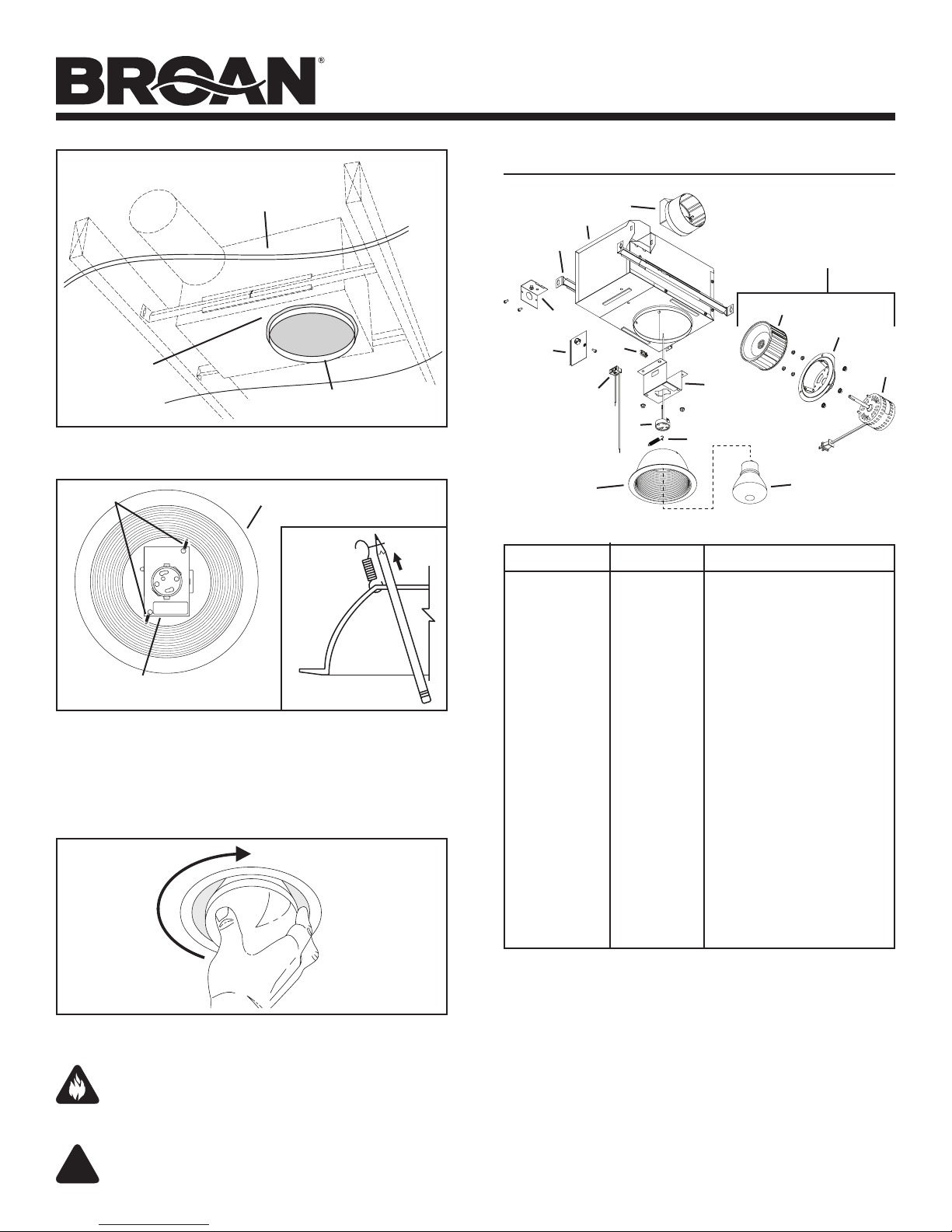
3. La bombilla LED que se utiliza con este producto se gira dentro
del receptáculo de la bombilla. No intente introducir o retirar la
bombilla empujándola directamente hacia dentro o tirando de
ella hacia abajo.
4. Lea la etiqueta de especificaciones del producto para ver información
y requisitos adicionales.
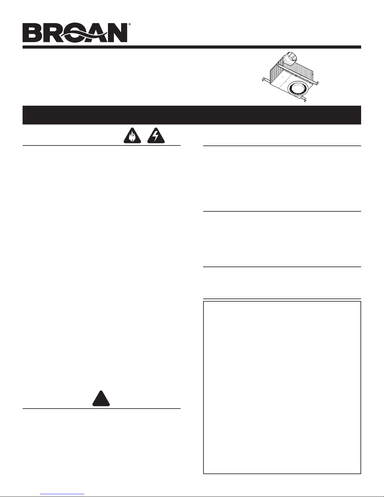
VENTILADOR CON LÁMPARA
LED EMPOTRADO
LEA Y CONSERVE ESTAS INSTRUCCIONES
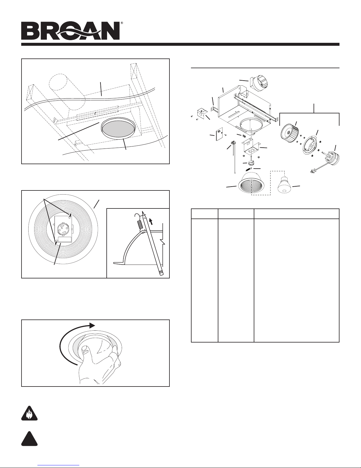
Para limpiar el anillo/deflector: Límpielo con una aspiradora que
tenga un cepillo suave como accesorio.También puede sacar el anillo/
deflector y limpiarlo con un trapo suave y detergente o jabónsuave.
Séquelo muy bien antes de volver a instalarlo.
Para limpiar el interior de la cubierta: Saque el anillo/deflector
y aspire el interior de la cubierta con una aspiradora que tenga un
cepillo suave como accesorio.
FUNCIONAMIENTO
El ventilador y la lámpara pueden funcionar con varias combinaciones
de interruptores de encendido/apagado y controles:
• Ventilador y lámpara controlados con un solo interruptor de
encendido/apagado
• Ventilador y lámpara controlados con interruptores de
encendido/apagado separados
• Ventilador controlado con un temporizador
• Ventilador controlado con un control de velocidad
En la sección “Conexión eléctrica” se describen varias opciones
decableado.
LIMPIEZA
MANTENIMIENTO
GARANTÍA
El motor está permanentemente lubricado. No lubrique ni desarme el motor.
En la sección “Piezas de repuesto” se encuentra una lista con ilustraciones
de tales piezas.
Ventiladores/lámparas de Broan – Garantía limitada
PERIODO DE GARANTÍA: Broan garantiza al consumidor comprador original del ventilador/lámpara
de Broan (el “Ventilador”) que el ventilador (excepto las bombillas/lámparas) estará libre de defectos
en materiales o mano de obra durante un período de tres (3) años a partir de la fecha de la compra
original. La garantía en las bombillas/lámparas provista con el ventilador es de un (1) año y no cubre
el rompimiento de las bombillas/lámparas. Esta garantía no cubre accesorios, como controles de
velocidad, que pueden comprarse por separado e instalarse con el ventilador.
El periodo de garantía limitada para las piezas de repuesto y para los ventiladores reparados o
reemplazados bajo esta garantía limitada continuará durante el resto del periodo de garantía original.
NO EXISTEN OTRAS GARANTÍAS, EXPLÍCITAS O IMPLÍCITAS, INCLUYENDO, ENTRE OTRAS,
GARANTÍAS IMPLÍCITAS DE COMERCIALIZACIÓN O APTITUD PARA UN PROPÓSITO PARTICULAR.
Durante este período de un año, Broan-NuTone, a su criterio, reparará o reemplazará sin cargo alguno
cualquier pieza o producto que se encuentre defectuoso bajo condiciones normales de uso y servicio.
ESTA GARANTÍA NO SE APLICA A TUBOS Y ARRANCADORES DE LÁMPARAS FLUORESCENTES.
Esta garantía no cubre (a) mantenimiento y servicio normales, ni (b) ningún producto o piezas que se
hayan sometido a uso inadecuado, negligencia, accidente, mantenimiento o reparación inadecuada
(no hecha por Broan-NuTone), instalación incorrecta o instalación en contra de las instrucciones de
instalación recomendadas.
La duración de una garantía implícita se limita al período de un año como se especifica para la garantía
explícita. Algunos estados no permiten limitaciones en cuanto al tiempo de vencimiento de una garantía
implícita, por lo que la limitación antes mencionada podría no aplicarse a usted.
LA OBLIGACIÓN DE BROAN-NUTONE DE REPARAR O REEMPLAZAR, A CRITERIO DE BROAN-NUTONE,
SERÁ EL ÚNICO Y EXCLUSIVO RECURSO DEL COMPRADOR BAJO ESTA GARANTÍA. BROAN-NUTONE
NO SERÁ RESPONSABLE POR DAÑOS INCIDENTALES, RESULTANTES O ESPECIALES QUE SURJAN
DEL USO O DESEMPEÑO DEL PRODUCTO O EN RELACIÓN CON EL MISMO. Algunos estados no
permiten la exclusión o la limitación de daños incidentales o resultantes, de manera que es posible
que la limitación antedicha no se aplique en su caso.
Esta garantía le otorga derechos legales específicos, y usted podría tener otros derechos que varían
de un estado a otro. Esta garantía sustituye todas las garantías anteriores.
Para tener derecho al servicio de la garantía, usted debe (a) notificar a Broan-NuTone a la dirección o
número de teléfono que aparecen abajo, (b) proporcionar el número de modelo y la identificación de la
pieza y (c) describir la naturaleza de cualquier defecto en el producto o pieza. En el momento de solicitar
el servicio cubierto por la garantía, debe presentar un comprobante de la fecha original de compra.
Broan-NuTone LLC Hartford, Wisconsin www.broan.com 800-558-1711