USE AND CARE (Cont nued)
TIMER ADJUSTMENT (Hum d ty Sensor)
The SENSAIRE® fan/light/night light has a "TIMER" that controls the length of
time that the fan remains ON (a) after the sensor has stopped sensing a rise in
humidity and the humidity level is below the user-adjustable set-point or (b) after
being energized by cycling the power switch. It can be adjusted from 5 to 60
minutes (factory-set at approx. 20 minutes).
To adjust the "TIMER":
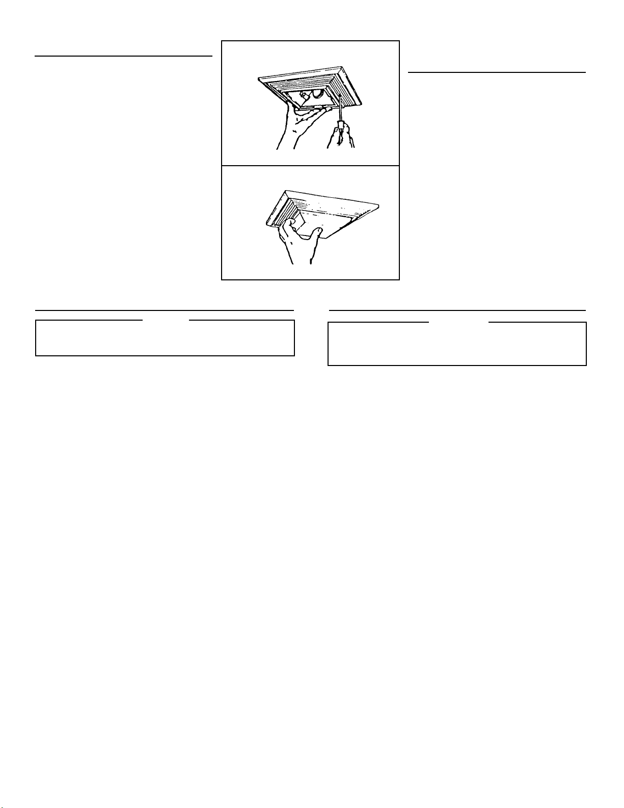
1. Disconnect power at service entrance and remove light lens.
2. Through the grille, locate the screwdriver slot marked "TIMER".
3. Using a small, flat-blade screwdriver, carefully rotate the "TIMER" adjustment
to desired setting (from 5 to 60 minutes).
4. Check operation by cycling the power switch as instructed under "MANUAL
ON WITH TIMED OFF (Fan)" or by turning on a humidity source until the fan
turns on.
5. Turn humidity source off and time the unit.
6. Repeat above steps if necessary.
TIMER ADJUSTMENT (Mot on Sensor)
The SENSAIRE® fan/light/night light has a "TIMER" that controls the length of
time that the light remains ON after motion has stopped. It can be adjusted from 5
to 60 minutes (factory-set at approx. 20 minutes).
To adjust the "TIMER":
1. Disconnect power at service entrance.
2. Remove grille.
3. Locate the hole marked "TIMER"
on the side of the motion control assembly.
4. Using a small, flat-blade screwdriver, carefully rotate the "TIMER" adjustment
to desired setting (from 5 to 60 minutes).
5. Replace grille.
6. Turn on power and wait approximately 1 minute before activating unit. After
unit turns ON, stay outside of its viewing area and time the unit.
7. Repeat above steps if necessary.
VIEWING AREA ADJUSTMENT (MOTION SENSOR)
The viewing area below the unit is cone-shaped with a diameter of approximately
11 ft. at floor level in an 8 ft. high room. The viewing area can be reduced by
applying a mask to the sensor lens.
Two washer-shaped masks are provided: The larger diameter mask will reduce
the viewing area to approximately 7 ft; the smaller diameter mask (used with the
larger one) will reduce the viewing area to a diameter of approximately 3 ft.
To prevent the unit from sensing from a certain direction, (adjacent hallway, for
example), cut and use a portion of the mask.
To mask the lens:
1. Remove the mask from its backing and apply it to the lens with light pressure.
2. Turn unit ON and wait approximately 1 minute before checking operation.
3. If necessary, cut out a portion of the mask with a pair of scissors and re-apply
to lens.
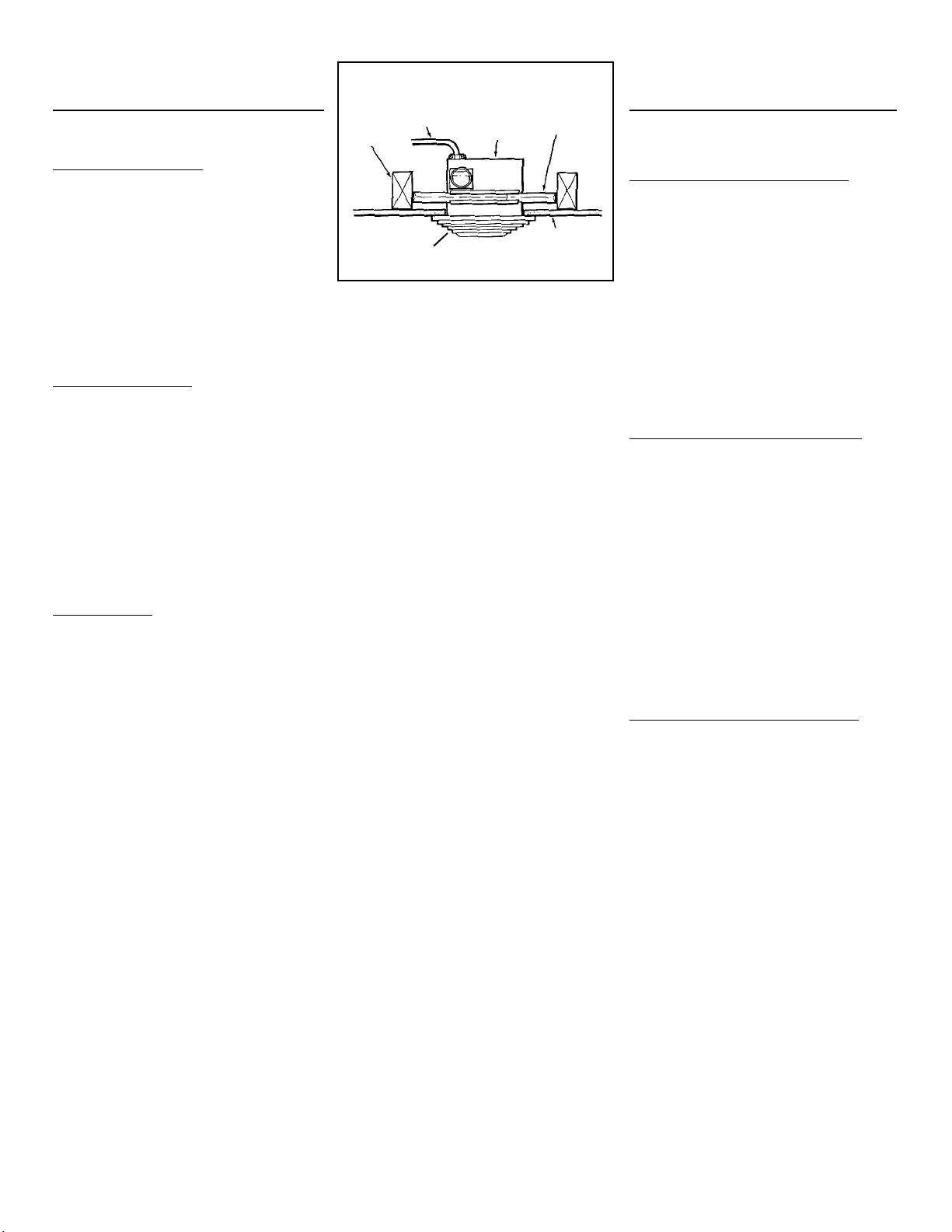
HUMIDITY SENSOR CLEANING
The humidity sensor is behind the grille. The sensor will operate most reliably
when cleaned occasionally as follows:
1. Disconnect power at service entrance.
2. Remove the grille. Use a dry dustcloth of lightly vacuum to clean sensor and
grille. DO NOT USE ABRASIVE CLOTH, STEEL WOOL PADS, OR SCOUR-
ING POWDERS.
3. DO NOT USE cleaning sprays, solvents, or water on or near the sensor!
MOTION SENSOR CLEANING
The motion sensor is permanently mounted in the grille and cannot be disas-
sembled for cleaning. The sensor will operate most reliably when the lens is cleaned
occasionally as follows:
1. Disconnect power at service entrance.
2. Use a dry dustcloth or lightly vacuum to clean lens and grille. DO NOT USE
ABRASIVE CLOTH, STEEL WOOL PADS, OR SCOURING POWDERS.
3. DO NOT USE cleaning sprays, solvents, or water on or near the sensor!
FAN ASSEMBLY CLEANING
1. Disconnect power at service entrance.
2. Remove grille and unplug the light/night light, sensors and fan. Disengage cap-
tive screw and lower fan assembly from housing. Gently vacuum fan, motor,
and interior of housing. METAL AND ELECTRICAL PARTS SHOULD NEVER
BE IMMERSED IN WATER.
3. Motor is permanently lubricated. No additional lubrication is necessary.
USO Y MANTENIMIENTO (Cont nuo)
COMO GRADUAR EL TEMPORIZADOR (SENSOR DE HUMEDAD)
El ventilador con luces diurna y nocturna SENSAIRE® lleva un temporizador (TIMER)
que controla el tiempo que el ventilador queda prendido (ON) (a) después que el
sensor ha dejado de detectar un aumento de la humedad y el nivel de humedad es
menor que el punto fijado por el usuario o (b) después de reciclar el interruptor de
potencia. Se puede ajustarlo de 5 a 60 minutos (el reglaje de fábrica es
aproximadamente 20 minutos).
Para graduar el temporizador (TIMER):
1. Desconecte la fuerza en el servicio de entrada y quite los cristales de las luces.
2. A través de la rejilla, ubique la ranura para destornillador marcada "TIMER".
3. Con un destornillador pequeño de hoja plana haga girar con cuidado el reglaje
del temporizador (TIMER) hasta el punto deseado (de 5 a 60 minutos).
4. Verifique el funcionamiento reciclando el interruptor de potencia como se
indico en "ENCENDIDO MANUAL (ON) CON TEMPORIZADOR APAGADO
(OFF) (VENTILADOR)" o prendiendo un aparato que produzca humedad
hasta que se prenda el ventilador.
5. Apague el aparato y gradue el tiempo en la unidad.
6. Repita los pasos anteriores si es necesario.
COMO GRADUAR EL TEMPORIZADOR (SENSOR DE MOVIMIENTO)
El Ventilador con luces diurna y nocturna SENSAIRE® tiene un temporizador
(TIMER) que controla el tiempo que la luz permanece prendida (ON) después de
haber cesado el movimiento. Puede ajustarse de 5 a 60 minutos (el reglaje de
fábrica es aproximadamente 20 minutos).
Como Graduar el Temporizador (TIMER)
1. Desconecte la corriente en el servicio de entrada.
2. Quite la rejilla.
3. Ubique el orificio marcado "TIMER" en el costado del conjunto controlador
de movimiento.
4. Con un destornillador pequeño de hoja plana haga girar con cuidado el reglaje
del temporizador al punto deseado (de 5 a 60 minutos).
5. Reponga la rejilla.
6. Conecte la fuerza eléctrica y espere aproximadamente un minuto antes de
activar la unidad. Luego que la unidad se ha prendido (ON) permanezca
fuera del alcance de la visión de la unidad y gradue el tiempo.
7. Repita los pasos anteriores si es necesario.
AJUSTE DEL ÁREA DE VISIÓN (SENSOR DE MOVIMIENTO)
El área de visión por debajo de la unidad es en forma de cono con un diámetro
aproximado de 3,4 m al nivel del piso en un cuarto con una altura de 2,4 m. El
área de visión puede reducirse poniendo mascarilla o recuadro en las lentes del
sensor.
Se sumimistran dos mascarillas en forma de arandelas: la de mayor diámetro
reducirá la visión a aproximadamente 2 m; la de menor diámetro (en combinación
con la grande) reducirá la visión a un diámetro de aproximadamente 91 cm.
Para impedir que la unidad detecte imágenes que vienen de cierta dirección
(entrada o vestíbulo contiguo, por ejemplo), corte y use una sección de la
mascarilla.
Para cubrir las lentes:
1. Quite el respaldo de la mascarilla y aplíquela a las lentes con ligera presión.
2. Prenda la unidad (ON) y espere aproximadamente un minuto antes de
verificar la operación.
3. Si fuera necesario, corte una sección de la mascarilla con tijeras y vuelva a
aplicarla a la lente.
COMO LIMPIAR EL SENSOR DE LA HUMEDAD
El sensor de la humedad se halla detrás de la rejilla. El sensor funcionará más
eficientemente cuando se lo limpie de cuando en cuando así:
1. Desconecte la corriente eléctrica en el servicio de entrada.
2. Quite la rejilla. Emplee un trapo seco para despolvar o la aspiradora para
limpiear las sensor y rejilla. NO EMPLEE TELAS ABRASIVAS,
ALMOHADILLAS de VIRUTAS de ACERO o POLVOS para RESTREGAR.
3. ¡NO EMPLEE rociadoras, solventes, o agua en o cerca del sensor!
COMO LIMPIAR EL SENSOR DE MOVIMIENTO
El sensor de movimiento está permanentemente instalado en la rejilla y no puede
desarmarse para limpiarlo. Funcionará más eficientemente si se limpia la lente
de cuando en cuando así:
1. Desconecte la corriente eléctrica en el servicio de entrada.
2. Emplee un trapo seco para despolvar o la aspiradora para limpiar las lentes
y rejilla. NO EMPLEE TELAS ABRASIVAS, ALMOHADILLAS de VIRUTAS
de ACERO o POLVOS para RESTREGAR.
3. ¡NO EMPLEE rociadoras, solventes o agua en o cerca del sensor!
COMO LIMPIAR EL CONJUNTO VENTILADOR
1. Desconecte la corriente eléctrica en el servicio de entrada.
2. Quite la rejilla y desconecte las luces, los sensores y el ventilador. Desune el
tornillo cautivo y baje el conjunto ventilador de la caja. Con la aspiradora
limpie con cuidado el ventilador, el motor y el interior de la caja. LAS PARTES
METÁLICAS y ELÉCTRICAS NUNCA DEBEN SUMERGIRSE en AGUA.
3. El motor lleva lubricación permanente y no se necesita lubricación adicional.
6