Bron kobold BB200 User manual

1
Operating instructions
BB200
www.bron-kobold.com

2
Operating instructions
BB 200
Before use
Please read all the information contained in these operating instructions carefully. They
contain important details on the use, safety and maintenance of the lighting equipment.
Keep these operating instructions in a safe place and pass them on to further users if
necessary.
Observe the safety instructions.
Important safety instructions
When using your lighting equipment, basic safety precautions should always be followed,
including the following:
1. Read and understand all instructions before using.
2. Close supervision is necessary when any appliance is used near children. Do not leave
appliance unattended while in use. Animals must be kept away from the appliance.
3. The lamp and the accessories mounted onto the lamp may heat up to high
temperatures, so please handle with care.
4. Do not operate lamp with a damaged cable or if the lamp has been dropped or
damaged - until it has been examined by a qualified serviceman.
5. Position the cable so that it will not be tripped over, pulled, or make contact with hot
surfaces.
6. To reduce the risk of electric shock, never open this unit: take it to a qualified
serviceman when service or repair work is required. Incorrect reassembly can cause
electric shock when the equipment is subsequently used.
7. The use of an accessory attachment not recommended by the manufacturer may
cause a risk of fire, electric shock, or injury to persons.
8. The ballast unit BB 200 is fully compatible with the other kobold 200 W daylight
systems.

3
Attention: Read before starting up
- Protect the unit from water.
- To ensure maximum service life of the lamp, allow it to heat up for approx. 1 minute
without interruption.
- Always disconnect the ballast unit from the battery before cleaning or servicing and
when not in use. Never pull on the cable itself; pull only on the plug housing.
- To prevent overheating, do not obstruct the free air flow through the ventilation slots
during operation.
- To reduce the risk of electric shock, do not disassemble the equipment, but take it to a
qualified serviceman when service or repair work is required. Incorrect reassembly can
cause electric shock when the equipment is subsequently used.
- Before replacing fuses or the lamp, disconnect the ballast unit from the battery.
- The equipment is not suitable for use in explosion-hazard areas.
- Do not operate the lamp without a safety glass or with a damaged safety glass. Lamps
may burst; the safety glass will retain the hot fragments.
- Like natural daylight, HMI/MSR light contains a certain proportion of UV radiation. The
safety glass reduces the UV content to safe levels for normal operating distances.
When used at close operating distance, limit the exposure time of unprotected skin.

4
1. Starting up
- Connect the ballast unit to the battery. The ballast unit is designed for 30V batteries,
but it can also be used with 24V batteries. In this case the output power is
automatically limited to 170W maximum.
- The ballast unit is switched on by means of the on/off switch on the lamp. The green
LED lights up (operating indicator).
- The ballast unit is equipped with an automatic heat-up device, so that the operating
temperature is achieved after only 1 minute. In this period the unit should only be
switched off if absolutely necessary in order to prolong the service life of the lamp.
- The optimal colour temperature is achieved after approx. 3 minutes of operation.
- If the lamp cannot be triggered, the ballast unit stops the trigger process after about 1.5
s and the red LED lights up. A new attempt to trigger can be initiated by operating the
on/off switch again. After 10 attempts the unit will block the trigger circuit for a cool
down period of approx. 30 seconds. After that further attempts are possible.
- Ensure that the ventilation slots are not covered during operation.
2. Power regulation
The required light output can be set (100 % - 60 % adjustment range) with the power
regulator. It should be noted that the colour temperature can change with the power output
depending on the type of lamp used.
During heat-up the power is automatically set to full until the operating temperature is
achieved. The blocking time of the dimmer depends on the lamp temperature when
switching on and can vary between 5 s and 40 s.
3. Installing or replacing the lamp
Never replace a lamp without first disconnecting the lamp base from the ballast unit.
Please observe the operating instructions of the lamp.

5
4. Connecting or replacing the battery
The ballast unit BB 200 is available in 3 variants:
1. with slide lock system
By pressing the security mechanism at the side of the slide lock system, the battery
can be inserted respectively removed.
2. for Cannon S12 2-pole plug
To connect respectively disconnect the ballast unit from the battery, tighten or release
the cap nut on the plug. Please observe: Never pull on the cable itself; pull only on
the plug housing.
3. for XLR 4-pole plug
To connect the ballast unit to the battery just plug in the corresponding connection, to
disconnect, the security mechanism on the socket must be pressed, so that the plug
can be pulled out. Please observe: Never pull on the cable itself; pull only on the plug
housing.
5. LED Display
• Green LED is lit continuously: normal operating mode
• Green LED is flashing: the battery voltage has dropped to 26V – 22V. The lamp is
now operated at a reduced power level according to the diagram below.
• Red LED is blinking: the battery voltage has dropped to 22V – 19V or the
thermoprotection is activated reducing the power continuously down to 60%. The
power reduction enables the user to recognize the situation and delays the final
shut-down.
• Red LED is lit continuously: the unit has stopped operating for one of the
following reasons:
1. The battery voltage has dropped below 19V.
2. The overload protection has stopped the trigger circuit after approx. 10
unsuccessful attempts to trigger. After 30 seconds further attempts are possible.
3. The temperature of the ballast unit has exceeded a safe limit.
4. Short circuit in the lamp.
5. Technical fault

6
If the red LED is lit continuously the lamp must be switched off. This display is
shown for a few seconds only. Then the red LED extinguishes in order to save
battery current.
Power = f ( U Batterie )
0
50
100
150
200
250
0 5 10 15 20 25 30 35
U Batterie (V)
Power (W)

7
6. Technical data
________________________________________________________________________
Operation of kobold equipment with motor-generators
Kobold equipment is basically suitable for operation with motor-generators provided that the supply voltage
remains within the tolerance limits of 200-264V or 95-135V respectively under all load conditions (including
capacitive load). Experience shows that this usually requires electronically stabilized motor-generators.
When connected to unstabilized motor-generators voltage peaks of 300V and over could be observed. This
may cause damage for which we cannot assume any responsibility.
________________________________________________________________________
Rated output 200W
Voltage range 30V battery 26V – 34V DC
Voltage range 24V battery 22V – 25V DC output limited to 170W
Automatic cut-off at < 19V
Ignition possible from > 22V
Power consumption 215W
Current consumption standby 0.3 mA
Efficiency 93%
Ambient temperature -5° to 45°C
Operation possible up to 45° to 60°C autom. power reduction to 50%
Storage temperature -20° to 80°C
Lamp frequency 400Hz
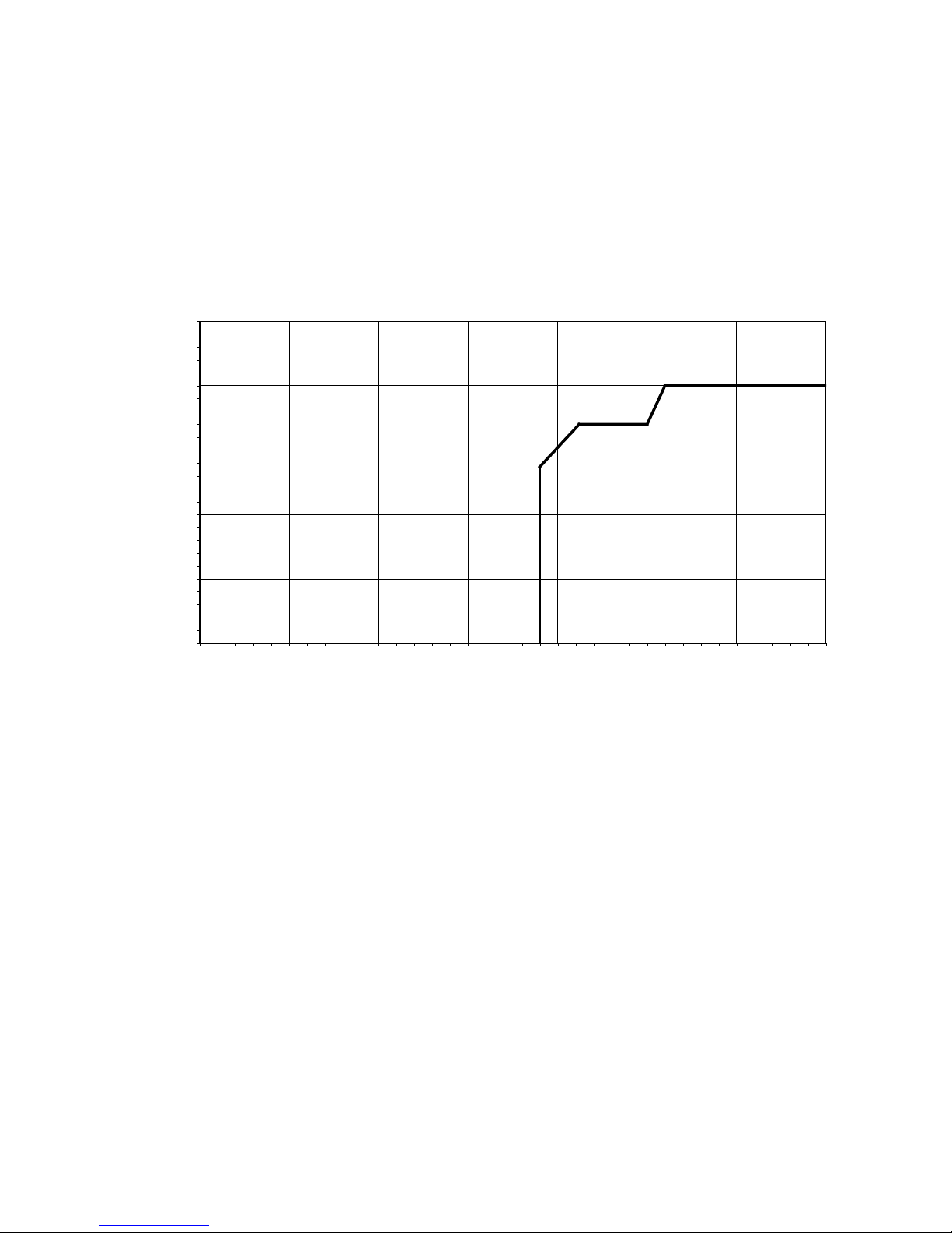
Power variation 100% to 60%
Stabilization power stabilizer with automatic heat-up device
achieving lamp operating temperature in 1 minute
Fuse 10 AF
Dimensions 65 x 105 x 165 mm
Weight 750 g
Alarm functions low battery voltage
ignition overload protection
temperature monitor
technical fault
lamp shorted
LED – display green: operating indicator
red : warning
Protection IP 20, insulation class II
Standards EC directives: 73/23, 89/336
Lamp types Osram HMI 200 W/SE
Philips MSR 200 HR
Sylvania BA 200 SE HR
BB 200 variants:
With slide lock system Art. No. 742-0194
For Cannon S12 2-pole plug Art. No. 742-0193
For XLR 4-pole plug Art. No. 742-0191

8
Bron Elektronik AG
CH-4123 Allschwil
Schweiz (Switzerland)
Printed in Switzerland 11.03
Table of contents