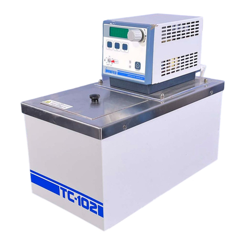
Brookfield TC-150MX User manual

TC-Series Circulating Baths with
MX Temperature Controller
Operator’s Manual
110-509 BEL/EN 06 September 2018
Models:
TC-150MX
TC-250MX
TC-450MX
TC-550MX
TC-650MX

110-509 BEL/EN
1
Table of Contents
Introduction .................................................................................................................................................2
Brookfield Circulating Baths with MX Temperature Controller .................................................................2
Performance Specifications......................................................................................................................3
Heating and Cooling Curves.....................................................................................................................4
General Safety Information.......................................................................................................................5
Safety Recommendations.........................................................................................................................6
Regulatory Compliance and Testing ........................................................................................................7
Unpacking Your Circulator........................................................................................................................7
Package Contents ....................................................................................................................................8
Controls and Components........................................................................................................................9
Quick-Start.................................................................................................................................................12
Installation and Startup ............................................................................................................................14
General Site Requirements ....................................................................................................................14
Adding Liquid to the Bath Reservoir.......................................................................................................14
External Closed Loop Circulation ...........................................................................................................15
Refrigeration Control Connections (Refrigerating/Heating Circulators only)................................16
Electrical Power......................................................................................................................................17
Controller Setup......................................................................................................................................18
Power .................................................................................................................................................18
Safety Set Temperature .....................................................................................................................18
Normal Operation......................................................................................................................................19
Keys and Controls ..................................................................................................................................19
Turning Your Circulator ON....................................................................................................................19
Main Operational Display........................................................................................................................19
Set-Up Sub-Menus.................................................................................................................................20
Adjusting the Temperature Set Point......................................................................................................20
Selecting the Temperature Unit..............................................................................................................21
Setting the Offset Calibration..................................................................................................................22
Setting the Low Limit Temperature.........................................................................................................23
Setting the High Limit Temperature........................................................................................................24
Adjusting the Auto Cool Temperature ....................................................................................................25
Resetting the Factory Default Values.....................................................................................................26
Loss of Power Restart ............................................................................................................................26
Display Messages and Alarms ................................................................................................................27
Routine Maintenance and Troubleshooting...........................................................................................28
Maintaining Clear Bath Water.................................................................................................................28
Draining the Bath Reservoir ...................................................................................................................28
Checking the Over-Temperature Safety System....................................................................................29
Cleaning Your Circulator.........................................................................................................................30
Temperature Controller ......................................................................................................................30
Bath Reservoir....................................................................................................................................30
Condenser, Air Vents, and Reusable Filter (Refrigerated Models only) ............................................30
Temperature Controller Removal and Re-Installation............................................................................31
Troubleshooting Chart............................................................................................................................33
Technical Information...............................................................................................................................35
Reservoir Fluids......................................................................................................................................35
Application Notes....................................................................................................................................36
Equipment Disposal (WEEE Directive) ...................................................................................................37
Replacement Parts, Optional Accessories & Fluids .............................................................................38
Warranty Repair and Service ...................................................................................................................39

110-509 BEL/EN
2
Introduction
Thank you for choosing a Brookfield Circulating Bath with MX Temperature Controller. It is intended for
the precise temperature control of suitable liquids in a reservoir. Extremely easy to use and maintain, it
combines design innovation with highly intuitive operation to deliver convenient and versatile liquid
temperature control for a wide range of applications.
WARNING: Brookfield Circulating Baths are not intended for directly controlling the temperature of
foods, pharmaceuticals, medicines, or other objects which may be ingested by or injected in humans
or animals. Any such objects must be isolated from contact with the bath fluid and bath surfaces.
Here are some of the features that make your Circulating Bath so user-friendly:
•Simple, intuitive operation
•Displays actual and set point temperature simultaneously
•Powerful pump, easy flow adjustment
•External circulation capability
•Fully enclosed housing prevents direct contact with pump and heater, yet provides quick
access for inspection and cleaning
•Suitable for use with Class I non-flammable fluids per DIN 12876-1
It will take you very little time to get your new Circulating Bath installed and running. This Operator’s
Manual is designed to guide you quickly through the process. We recommend that you read it thoroughly
before you begin.
Brookfield Circulating Baths with MX Temperature Controller
Model Type
Reservoir
Capacity
Temperature Range
°C
°F
TC-150MX Heat only Circulator *
6 liters
Ambient +10°C to 135°C
Ambient +20° to 275°F
TC-250MX Heat only Circulator *
10 liters
Ambient +10°C to 135°C
Ambient +20° to 275°F
TC-450MX Heat only Circulator
28 liters
Ambient +10°C to 135°C
Ambient +20° to 275°F
TC-550MX Refrigerating/Heating
Circulator
7 liters
-20° to 135°C
-4° to 275°F
TC-650MX Refrigerating/Heating
Circulator
7 liters
-20° to 135°C
-4° to 275°F
*. Compatible with optional TC-351 Chiller for low temperature operation to -15°C (5°F).

110-509 BEL/EN
3
Performance Specifications
Operating Temperature Range:
Model dependent; see table below
Temperature Stability:
±0.07C (±0.13°F)
Pump Type:
1-speed pressure
60Hz models
50Hz models
Maximum Pressure:
2.3 psi (0.16 bar)
1.8 psi (0.12 bar)
Maximum Pressure Flow Rate:
3.6 gpm (13.5 lpm)
3.1 gpm (11.9 lpm)
Heater Wattage:
1100 watts
1100 watts
Model Type
Reservoir
Capacity
Internal
Working Area
(L x W x D)
Overall
Dimensions
(L x W x H)
Gross
Weight
Temperature
Range
TC-150MX
Heated Circulator
6 liters
4.5 x 4.0 x 6.0 in.
11.4 x 10.2 x 15.2 cm
13.4 x 8.1 x 16.0 in.
34.0 x 20.6 x 40.6 cm
20 lbs.
9.1 kg
Ambient +10° to 135°C
Ambient +20° to 275°F
TC-250MX
Heated Circulator
10 liters
5.0 x 11.0 x 6.0 in.
12.7 x 27.9 x 15.2 cm
13.9 x 13.5 x 16.0 in.
35.3 x 34.3 x 40.6 cm
39 lbs.
17.7 kg
Ambient +10° to 135°C
Ambient +20° to 275°F
TC-450MX
Heated Circulator
28 liters
12.1 x 10.4 x 8.0 in.
30.7 x 26.4 x 20.3 cm
20.9 x 13.5 x 18.0 in.
53.1 x 34.3 x 45.7 cm
66 lbs.
29.9 kg
Ambient +10° to 135°C
Ambient +20° to 275°F
TC-550MX
Refrigerating/
Heating Circulator
7 liters
6.18 x 5.59 x 5.0 in.
15.7 x 14.2 x 12.7 cm
23.2 x 16.2 x 17.3 in.
58.9 x 41.1 x 43.9 cm
84 lbs.
38.1 kg
-20° to 135°C
-4° to 275°F
TC-650MX
Refrigerating/
Heating Circulator
7 liters
6.18 x 5.59 x 5.1 in.
15.7 x 14.2 x 12.9 cm
21.3 x 8.7 x 25.4 in.
54.1 x 22.1 x 64.5 cm
84 lbs.
38.1 kg
-20° to 135°C
-4° to 275°F
Model Type
Electrical Requirements **
120V Units
240V Units
TC-150MX Heated Circulator
120V, 60Hz, 10A
240V, 50Hz, 6A
TC-250MX Heated Circulator
120V, 60Hz, 10A
240V, 50Hz, 6A
TC-450MX Heated Circulator
120V, 60Hz, 10A
240V, 50Hz, 6A
TC-550MX Refrigerating/Heating Circulator
120V, 60Hz, 12A
240V, 50Hz, 8A
TC-650MX Refrigerating/Heating Circulator
120V, 60Hz, 12A
240V, 50Hz, 8A
** Voltage Utilization Range: +/- 10% from Listed Nominal Voltage
Environmental Conditions Indoor use only
Maximum Altitude: 2000 meter
Operating Ambient: 5° to 35°C (41° to 95°F)
Relative Humidity: 80%, non-condensing
Installation Category: II
Pollution Degree: 2
Ingress Protection: IP 31
Climate Class: SN
Software Class: B
Output Waveform: Sinusoidal
Specifications subject to change without notice.

110-509 BEL/EN
4
Heating and Cooling Curves
TC-550 and TC-650 Heating Rates (60 Hz & 50 Hz)
TC-550 and TC-650 Cooling Rates (60 Hz & 50 Hz)
TC-150, TC-250 and TC-450 Heating Rates (60 & 50 Hz)
0
20
40
60
80
100
120
140
0
20
40
60
80
100
120
Time (Minutes)
Fluid Temperature (°C)
TC-150MX
TC-250MX
TC-450MX

110-509 BEL/EN
5
General Safety Information
When installed, operated, and maintained according to the directions in this manual and common safety
procedures, your Circulating Bath should provide safe and reliable temperature control. Please ensure
that all individuals involved in the installation, operation, or maintenance of this Circulating Bath read this
manual thoroughly prior to working with the unit.
This symbol alerts you to a wide range of potential dangers.
This symbol advises danger from electricity or electric shock.
This symbol indicates that a hot surface may be present.
This symbol marks information that is particularly important.
This symbol indicates alternating current.
/
These symbols on the Power Switch / Circuit Breaker indicate that they place the main power supply
ON / OFF.
This symbol on the Power Key indicates that it places the unit in a standby mode. It DOES NOT fully
disconnect the unit from the power supply.
This symbol indicates a protective conductor terminal.
Read all instructions pertaining to safety, set-up, operation, and maintenance.
Proper operation is the user’s responsibility.

110-509 BEL/EN
6
Safety Recommendations
To prevent injury to personnel and/or damage to property, always follow your workplace’s safety
procedures when operating this equipment. You should also comply with the following safety
recommendations:
WARNING:
•This Circulating Bath is suitable only for use with Class I non-flammable fluids (per DIN 12876-1).
•Be aware of the chemical hazards that may be associated with the bath fluid used. Observe all
safety warnings for the fluids used as well as those contained in the material safety data sheet.
•Use only recommended bath fluids; see Technical Information in the rear of this manual for
recommended fluids.
•Use only non-acid bath fluids.
WARNING:
•Always connect the power cord on this Circulator to a grounded (3-prong) power outlet. Make
certain that the outlet is the same voltage and frequency as your unit.
•Never operate the Circulator with a damaged power cord.
•Always turn the Circulator OFF and disconnect mains power before performing any maintenance
or service.
WARNING:
•Never operate the Circulator without bath fluid in the reservoir. Periodically check the reservoir to
ensure that the liquid depth is within acceptable levels. Always refill the reservoir using the same
bath fluid that is already in the reservoir. Bath oil must not contain any water contaminants and
should be preheated to the actual bath temperature before adding as there is an explosion hazard
at high temperatures.
•Always drain all fluid from the reservoir before moving or lifting your Circulator. Be sure to follow
your organization’s procedures and practices regarding the safe lifting and relocation of heavy
objects.
WARNING:
•Always allow the bath fluid to cool to ambient temperature before draining.
•The reservoir cover, top deck, and/or external pump connections may become hot with continuous
use. Exercise caution when touching these parts.
WARNING: It is the user’s responsibility to properly decontaminate the unit in the event hazardous
materials are spilled on exterior or interior surfaces. Consult manufacturer if there is any doubt
regarding the compatibility of decontamination or cleaning agents.

110-509 BEL/EN
7
Regulatory Compliance and Testing
This equipment is compliant with the European Directive 2002/95/EC and its latest amendments on
Restrictions on Hazardous Substances (RoHS) and below the given limits of hazardous substances.
ETL Intertek (60 Hz units)
UL 61010-1 / CSA C22.2 No. 61010-1 —Safety Requirements for Measurement, Control, and
Laboratory Use; Part 1: General Requirements
UL 61010A-2-010 / CSA C22.2 No. 61010-2-010:04 —Safety Requirements for Measurement, Control,
and Laboratory Use; Part 2-010: Particular Requirements for Laboratory Equipment for the Heating of
Materials
UL 61010A-2-051 / CSA C22.2 No. 61010-2-051:04 —Safety Requirements for Measurement, Control,
and Laboratory Use; Part 2-051: Particular Requirements for Laboratory Equipment for the Mixing and
Stirring
CE (all units)
EC Low Voltage Directive 2006/95/EC
EC Electromagnetic Compatibility Directive 2004/108/EC
IEC 61010-1-2001
IEC 61010-2-2001
IEC 61326:2005 / EN 61326 : 2006
Unpacking Your Circulator
Your Circulator is packed in a special carton or cartons. You should keep the packaging, along with all
packing materials, until the unit has been installed and you are certain it is working properly.
CAUTION: Remove any loose packing material that may have fallen into the heater/pump housing
during shipping. Before powering up, check that nothing remains around the heater or Circulator
pump.
We recommend that you begin using your Circulator immediately to confirm proper operation, since
beyond one week you may be eligible for warranty repair only (rather than replacement). You’ll find
complete warranty information in the back of this manual.
In the unlikely event that the unit was damaged or does not operate properly, immediately contact the
transportation company, file a damage claim, and contact the company where your Circulator was
purchased.

110-509 BEL/EN
8
Package Contents
The items included with your Circulator will vary depending on which model Circulating Bath you
purchased.
Heating Only Circulators
Refrigerating / Heating
Circulators
TC-
150MX
TC-
250MX
TC-
450MX
TC-
550MX
TC-
650MX
Resource Disk (with
Operator’s Manual)
PS110-817
Fittings for External
Applications
1/2" ID Black Silicone Hose, 3" Long (2 pcs)
1/2" HB x 1/4" HB GF Nylon Fitting (2 pcs)
Bypass Tubing with
Spring
PS510-713
Latex Tubing
(6-ft., 0.25” ID)
EX-Tubing
(Maximum temperature 80°C) **
Beaker Platform(s)
for Bath Reservoir
600 mL
1000 mL
PS703-038
PS703-038
PS703-039
PS703-038
PS703-038
Rack for Bloom Jars
PS540-563
Deck Lid(s)
PS510-781
PS510-781
PS510-782
PS510-783
PS510-784
PS510-784
Gabled Reservoir
Cover
PS540-562
IEC Power Cord
1
Certificate of
Compliance
1
Quick-Start Guide
1
**. For higher temperatures, use part number ULA-45A

110-509 BEL/EN
9
Controls and Components
MX Controller
Backlit Digital Display
Up Arrow Button
Down Arrow Button
Menu Button
Power Button
Safety Thermostat
(under cover plate)
Actual Bath Temperature
Set Point Temperature
Heating
Circulating
Refrigerating

110-509 BEL/EN
10
Refrigerating/Heating Baths
MX Controller
Reservoir Cover
Reservoir Drain Valve and Port
(behind access panel on
TC-650MX)
Washable Air Filter
(behind access panel)
Drain Valve and Port
(right side on model
TC-550MX)
Thermometer Port
Power Switch / Circuit Breaker
IEC Power Connection to Mains
Refrigeration Control Cable
Connection
IEC Power Cord to
Refrigeration Power Module
Refrigeration Control Cable to
Refrigeration Power Module
Cooling System Status Display
Power
Cooling
Cooling Fault
Fan

110-509 BEL/EN
11
Heating Circulators
WARNING: Do not lift bath by grasping the Temperature Controller or top deck. Always disconnect
electrical power and drain fluid from bath before moving.
WARNING: To avoid the potential for burns, allow the Circulator to cool completely before cleaning
or performing any maintenance.
MX Controller
Reservoir Cover(s)
Thermometer Port
IEC Power Cord
to Mains
Tap Water Cooling
Coil Ports

110-509 BEL/EN
12
Quick-Start
Unless otherwise specified, quick-start instructions apply to all models.
See Installation & Startup for additional information.
1
Fill reservoir with fluid
2
Models TC-150 and TC-250:
Connect cooling coils to
external water line
(Use of cooling coils is
optional)
3
Connect all power cords and
control cables
Maximum: 1 in / 2.54 cm
below the underside of the
top deck
Minimum: 2.6 in. / 6.7 cm
below the underside of the
top deck
Heat only Circulators
IEC Power Cord
(Temperature
Controller to
Refrigeration
Power Module
Refrigeration
control cable
(Temperature
Controller to
Refrigeration
Power
Module)
IEC Power
Cord to Mains
Refrigerated
Circulators

110-509 BEL/EN
13
4
Turn Power Switch / Circuit
Breaker ON
(Refrigerating/Heating Baths
only)
5
Turn Controller ON
6
Enter temperature
set point
7
Set safety thermostat once
unit reaches set point
(See Installation and Startup,
Controller Setup for details)

110-509 BEL/EN
14
Installation and Startup
Your Circulating Bath with MX Temperature Controller is designed to be simple to set-up and install. The
only tools required are a flat-head screwdriver and a container for adding water or another suitable fluid to
the bath reservoir.
General Site Requirements
Locate your Circulator on a level surface free from drafts and direct sunlight. Do not place it where there
are corrosive fumes, excessive moisture, high room temperatures, or in excessively dusty areas.
Refrigerating / Heating Circulators must be 10.2 cm / 4 inches or more away from walls or vertical
surfaces so that airflow is not restricted.
Avoid voltage drops by using properly grounded power outlets wired with 14 gauge or larger diameter
wire and if possible, be close to the power distribution panel. The use of extension cords is not
recommended; this will reduce the potential for problems caused by low line voltage.
Adding Liquid to the Bath Reservoir
WARNING: Read the safety data sheet for the bath fluid being used carefully before filling reservoir.
WARNING: See Technical Information in the rear of this manual for a list of compatible liquids.
WARNING: If the proper fluid level is not maintained, the heater coil may become exposed and
possibly damaged (fluid level too low) or the bath may overflow (fluid level too high).
The liquid in the reservoir should be maintained at a depth between 1 inch / 2.54 cm and 2.6 inches / 6.7
cm below the underside of the bath’s top deck. Upon start up, it may be necessary to add fluid to the bath
to compensate for the fluid required for external circulation. Likewise, be sure to compensate for fluid
displacement when placing samples or other materials in the Circulator’s reservoir. See Technical
Information, Reservoir Fluids.
WARNING: Always drain all fluid from the reservoir before moving or lifting your Circulator. Be sure
to follow your organization’s procedures and practices regarding the safe lifting and relocation of
heavy objects.
WARNING: To avoid the potential for burns, allow the Circulator to cool completely before cleaning
or performing any maintenance.
Maximum Liquid Level =:
1 in. / 2.54 cm
below the underside of the top deck
Minimum Liquid Level =
2.6 in. / 6.7 cm below the
underside of the top deck

110-509 BEL/EN
15
External Closed Loop Circulation
WARNING: When connecting tubing to an external application, it is the user’s responsibility to make
sure that the tubing and fittings connected to the Circulator are suitable for the fluid being used and
the temperature range of operation.
CAUTION: The Circulator’s bypass tubing is secured to the fluid inlet and outlet connections by high
temperature nylon hose clamps, which can be removed by carefully cutting them with diagonal
cutters.
CAUTION: Secure the tubing to the inlet and outlet fittings using hose clamps with a minimum ID of
7/8 inch (22 mm). Do not operate the unit without hose clamps.
WARNING: If the Circulating Bath will not be used for external circulation, the inlet and outlet ports
should remain connected using the Silicone bypass tubing provided with the unit.
The single speed pump on your Circulating Bath permits closed loop circulation to a Viscometer
accessory, such as the Brookfield Small Sample Adapter, via the 1/2 inch / 12.7 mm OD pump inlet and
outlet ports on the rear of the MX Controller. Use the fittings provided with the unit to make external
connections. If a higher flow rate is desired you can move the flow adjuster toward a closed position as
shown below:
APPLICATION NOTES:
To maintain adequate flow, avoid restrictions in the tubing.
When using the bath for external circulation the front Flow Control Slider must be open one click to the right.
The control stability of a closed loop system is better at the Viscometer accessory than in the immediate vicinity of the
heater (provided the accessory control point represents a constant load and is well insulated). For example, if you
circulate through a Viscometer at 50°C, the temperature variation observed in the reservoir may be ±0.1°C, whereas
in the viscometer it may be only ±0.05°C.
Although stability is better at the Viscometer accessory control point, depending on the insulation and length of tubing
used, the accuracy of temperature may be slightly different than the temperature indicated in the reservoir.
Flow Adjuster
Fluid Inlet Port
Fluid Outlet Port
Bypass Tubing
(cut clamps and remove)
Flexible Tubing
(1/2” ID x 2-1/8” long)
Hose Clamps
(use a 1/4” nut driver or
flat blade screw driver
to tighten)
Barbed Hose Adapter Fittings
1/2” x 1/4”
Close

110-509 BEL/EN
16
**Differences in elevation between the circulator and external device will reduce flow rate.
Connection to external devices which utilize a Quick Connect Coupling, such as R/S Series Rheometer,
is not recommended due to potential reduction in flow rate of circulating fluid, which may ultimately affect
temperature stability at the external device.
Refrigeration Control Connections (Refrigerating/Heating Circulators only)
Attach the refrigeration control cable connected to the rear of the Temperature Controller to the
refrigeration control connection on the Refrigeration Power Module.
Refrigeration
Control Cable
Refrigeration Control
Connection

110-509 BEL/EN
17
Electrical Power
WARNING: The Circulator’s power cord must be connected to a properly grounded electrical
receptacle. Make certain that this electrical outlet is the same voltage and frequency as your
Circulator. The correct voltage and frequency for your Circulator are indicated on the identification
label on the back of the Controller.
CAUTION: The use of an extension cord is not recommended. If one is necessary, it must be
properly grounded and capable of handling the total wattage of the unit. The extension cord must not
cause more than a 10% drop in voltage to the unit.
Refrigerating / Heating Circulators
Attach the Temperature Controller’s power cord to the female IEC connector on the Refrigeration Power
Module.
Attach the 6-ft / 1.8 m power cord to the IEC electrical connection on the Refrigeration Power Module and
then plug the male connector into the Mains electrical outlet.
Place the Power Switch / Circuit Breaker on the Refrigeration Power Module in the ON position. The LCD
on the Controller will light and “Standby” will appear on the display.
All Other Circulators
Plug the male connector on the Temperature Controller’s
power cord into the Mains electrical outlet. The LCD on the
Controller will light and “Standby” will appear on the display.
NOTE: 50 Hz models supplied with a country
specific electrical cord and plug.
6 ft. / 1.82 m
IEC power cord
(Refrigeration Power
Module to Mains)
IEC power cord
(Temperature
Controller to
Refrigeration Power
Module)
IEC electrical connections
Power cord to Mains
IEC to IEC connector
(50 Hz models only)

110-509 BEL/EN
18
Controller Setup
Power
Press ; all characters and symbols on the LCD will momentarily light. The Circulator will begin running,
actual and set point temperatures will be displayed, and the word “SET” will be continuously lit. The
circulating symbol will also be lit and the heating or refrigerating symbol may be lit or flashing.
Safety Set Temperature
This is a “Do Not Exceed” temperature setting for your Circulator and is the temperature at which the
heater will be turned OFF should the liquid level in the bath drop too low or the Circulator malfunctions. It
is normally set about 5° higher than the desired operating temperature. Setting the Safety Set
temperature is a four-step process.
1. Using a flat blade screwdriver, rotate the Safety Thermostat
(located beneath the cover plate) clockwise until it stops.
2. Press the or key; “SET” will begin flashing. Continue
pressing the and keys until the set point temperature is
equal to your desired Safety Set temperature. “SET” will stop
flashing approximately 10 seconds after the desired
temperature has been entered. Allow the Circulator to
stabilize at this temperature.
3. Once the bath temperature has stabilized, slowly rotate the Safety
Thermostat counter-clockwise until you hear a soft “click;” the OVERTEMP or
LOW FLUID alarm symbol will appear on the display approximately 5-10
seconds later. At this point, the heater will also turn OFF.
4. Slowly rotate the Safety Thermostat clockwise until the alarm symbol
extinguishes (you may also feel a soft “click”). The heater should turn back
ON. You are now ready to start normal operation.
WARNING: The Safety Thermostat is user-adjustable from approximately 40° to 155°C. Do not force
the indicator dial beyond the stops at either end of the dial’s range.
Heating
Refrigerating
Circulatingl
OVERTEMP / LOW FLUID Alarm

110-509 BEL/EN
19
Normal Operation
Keys and Controls
Power
Turns the Circulator’s Temperature Controller ON.
Menu
Accesses the Temperature Controller’s set-up sub-menus. The items in
these sub-menus are used to configure the Controller’s general
operational parameters (temperature unit, upper and lower temperature
limits, offset calibration, etc.).
Up Arrow
Used to increase temperature set point and other operational
settings/values.
Down Arrow
Used to decrease temperature set point and other operational
settings/values.
Turning Your Circulator ON
Press the key.
All characters/symbols on the LCD will momentarily light. When the Circulator begins running, the actual
and set point temperatures will be displayed and the circulating symbol will be lit.
If the actual bath temperature is lower than the set point temperature, the heating symbol will also be lit.
Refrigerating/Heating Models: If the actual bath temperature is higher than the set point temperature, the
refrigerating symbol will be lit. It is normal for both the heating and refrigerating symbols to be lit
simultaneously when nearing or maintaining the set point temperature.
Main Operational Display
Actual Bath
Temperature
Set Point
Temperature
Heating
Refrigerating
Circulating
This manual suits for next models
4
Table of contents
Other Brookfield Laboratory Equipment manuals