Sorvall RT6000B User manual

SORVALL Ce nt r i f uge s
PN 07903-3
Issued July 1993
Du Pont Company
SORVALL®Products
Wilmington, Delaware 19898
U.S.A.
OPERATING
INSTRUCTIONS
SORVALL RT6000B
& T6000B
TABLETOP
CENTRIFUGES

Th is m a n u a l is a gu id e to th e u s e of th e
SORVALL®RT6000B and T6000B
Tabletop Centrifuges
Data herein has been verified and validated and is believed adequ ate for the intended use
of th e cen trifu ge. Becau se failu re to follow th e recom men dations set forth in th is m an u al
could produ ce personal inju ry or property damage, always follow the recommendations
set forth herein. Du Pont does not guarantee results and assumes no obligation for the
performance of rotors or other products that are not used in accordance with the
in stru ction s provided . Th is p u blica tion is n ot a licen se to opera te u n d er, n or a recom m en -
dation to infringe upon, any process patents.
Pu blication s prior to th e Issu e Date of th is m an u al may con tain data in apparen t con flict
with th at provided herein. Please consider all data in th is m anu al to be th e most cu rrent.
NOTES, CAUTIONS, an d WARNINGS with in th e text of th is m a n u a l are u s ed to em ph a size
im porta n t a n d critica l in s tru ction s .
WARNING: A Wa r n in g in fo r m s t h e op e r a t or of a h a za r d or a n u n s a fe p r a c t ic e t h a t c ou ld
result in personal injury, affect the operator’s health, or contaminate the
environment.
CAUTION: A C a u t io n in for m s t h e op e r a t or of a n u n s a fe p r a c t ic e t h a t c ou ld r e s u lt in
damage of equipment.
NOTE: A Not e h igh ligh t s e s s e n t ia l in for m a t ion .
© 1988 by E. I. du Pont de Nemours & Co.
SORVALL®
Centrifuges
ii
RT6000B & T6000B

Important Safety Information
Certain potentially dangerous conditions are inherent to the use of all centrifuges. To
ensure safe operation of this centrifuge, anyone using it should be aware of all safe
practices and take all precautions described below and throughout this manual.
WARNING
When using radioactive, toxic, or pathogenic materials, be aware of all characteristics of the
materials and the hazards associated with them in the event leakage occurs during
centrifugation. If leakage does occur, neither the centrifuge nor the rotor can protect you
from particles dispersed in the air. To protect yourself, we recommend additional precautions
be taken to prevent exposure to these materials, e.g., use of controlled ventilation or isolation
areas.
Always be aware of the possibility of contamination when using radioactive, toxic, or
pathogenic materials. Take all necessary precautions and use appropriate decontamination
procedures if exposure occurs.
The use of sealed rotors, buckets and/or sample containers will provide increased protection
from contamination during routine operation. However, these items will not guarantee
contamination protection from accidents resulting in damage to the rotor or buckets. Do not
run hazardous materials in the centrifuge unless placed in a biohazard enclosure and operated
using all appropriate safety precautions.
Never use any material capable of producing flammable or explosive vapors.
Never exceed the maximum rated speed of the installed rotor; to do so can cause rotor failure.
Always reduce (derate) rotor speed as instructed in this manual whenever:
• the rotor speed/temperature combination exceeds the solubility of the gradient material
and causes it to precipitate.
• the compartment load exceeds the maximum allowable compartment load specified. See
Chapter 3, Operation, page 3-6.
Failure to reduce rotor speed under these conditions can cause rotor failure.
CAUTION
Do not run or precool a rotor at the critical speed, as this will have a detrimental effect on
centrifuge component life. See Chapter 3, page 3-3.
Do not operate the centrifuge with a rotor out of balance. To do so can cause damage to the
centrifuge drive assembly.
Do not operate centrifuge without a rotor properly installed: rotor cover must be on and
locked in place, and the rotor locked to the centrifuge drive. See rotor instruction manual.
The centrifuge can be damaged if connected to the wrong voltage. Check the voltage before
plugging the centrifuge into a power source. Du Pont is not responsible for incorrect
installation.
Always maintain the centrifuge in the recommended manner. See Chapter 4, Maintenance.
Safety
SORVALL®
Centrifuges
iii

Table of Contents
Page
Safety Information Page . . . . . . . . . . . . . . . . . . . . . . . . . . . . . . . . . . . . . . . . . . iii
Chapter 1. DESCRIPTION
Centrifuge Description . . . . . . . . . . . . . . . . . . . . . . . . . . . . . . . . . . . . . . . . . . . 1-1
Centrifuge Specifications . . . . . . . . . . . . . . . . . . . . . . . . . . . . . . . . . . . . . . . . . 1-1
Rotors . . . . . . . . . . . . . . . . . . . . . . . . . . . . . . . . . . . . . . . . . . . . . . . . . . . . . . . 1-2
Chapter 2. INSTALLATION
In s p ection . . . . . . . . . . . . . . . . . . . . . . . . . . . . . . . . . . . . . . . . . . . . . . . . . . . . 2-1
Electrical Requirements . . . . . . . . . . . . . . . . . . . . . . . . . . . . . . . . . . . . . . . . . . 2-1
In s ta lla tion . . . . . . . . . . . . . . . . . . . . . . . . . . . . . . . . . . . . . . . . . . . . . . . . . . . . 2-2
Chapter 3. OPERATION
Controls and Indicators . . . . . . . . . . . . . . . . . . . . . . . . . . . . . . . . . . . . . . . . . . 3-1
Rotor Con siderations . . . . . . . . . . . . . . . . . . . . . . . . . . . . . . . . . . . . . . . . . . . . 3-2
Precooling a Rotor in the RT6000B Centrifu ge . . . . . . . . . . . . . . . . . . . . . . . . . 3-3
Ru nning Hazardou s Material . . . . . . . . . . . . . . . . . . . . . . . . . . . . . . . . . . . . . . 3-4
Operation . . . . . . . . . . . . . . . . . . . . . . . . . . . . . . . . . . . . . . . . . . . . . . . . . . . . . 3-4
Emergency Sample Recovery . . . . . . . . . . . . . . . . . . . . . . . . . . . . . . . . . . . . . . 3-6
Redu cing Speed for Rotor Com partm en t Loads in Excess
of Design Mass . . . . . . . . . . . . . . . . . . . . . . . . . . . . . . . . . . . . . . . . . . . . . . . 3-6
Chapter 4. MAINTENANCE
In s p ection a n d Clea n in g . . . . . . . . . . . . . . . . . . . . . . . . . . . . . . . . . . . . . . . . . . 4 -1
REV/MIN x 1000 Indicator Adjustment . . . . . . . . . . . . . . . . . . . . . . . . . . . . . . . . 4-2
Motor Bru s h In s pection a n d Repla cem en t . . . . . . . . . . . . . . . . . . . . . . . . . . . . 4-3
RT6000B CHAMBER TEMP°C Indicator Adjustment . . . . . . . . . . . . . . . . . . . . . 4-4
Parts Ordering In formation . . . . . . . . . . . . . . . . . . . . . . . . . . . . . . . . . . . . . . . . 4-4
Service Decontamination Policy . . . . . . . . . . . . . . . . . . . . . . . . . . . . . . . . . . . . 4-5
APPENDIX
Wa r r a n t y
In dex
Decontamination Certificates
SORVALL®
Centrifuges
Table of Contents
iv

List of Illustrations
Figure Page
3-1. Controls and Indicators . . . . . . . . . . . . . . . . . . . . . . . . . . . . . . . 3-1
3-2. Location of Mechanical Override Loop . . . . . . . . . . . . . . . . . . . . . 3-6
4-1. REV/MIN x 1000 In d ica tor Ad ju s t m en t . . . . . . . . . . . . . . . . . . . . . 4 -3
4-2. Motor Bru sh Assembly . . . . . . . . . . . . . . . . . . . . . . . . . . . . . . . . 4-4
4-3. CHAMBER TEMP°C Indicator Adju stment . . . . . . . . . . . . . . . . . . 4-4
List of Tables
Table Page
3-1. Controls and Indicators . . . . . . . . . . . . . . . . . . . . . . . . . . . . . . . 3-1
Table of Contents
SORVALL®
Centrifuges
v/vi

A PHOTOGRAPH OF THIS INSTRUMENT WAS NOT TAKEN AND THEREFORE
WILL NOT BE AVAILABLE FOR FIRST PRINTING OF MANUAL
Figu re 1 -1 . S ORVALL®R T6000B Refrigerated
Tabletop Centrifuge (T6000B not show n)
SORVALL®
Centrifuges
vi

SORVALL®
Centrifuges Description
1-1
Chapter 1
DESCRIPTION
Th is m a n u a l p rovid es you with t h e in for m a tion you n eed t o in s ta ll, op er a te a n d m a in ta in
you r SORVALL®RT6000B and T6000B Tabletop Centrifuges. If you encounter any
problem concerning either operation or maintenance that is not covered in this manual,
please contact our Marketing Technical Group for assistance. In the United States,
telephone toll free (800) 551-2121. Outside the United States, contact your local
distributor or agent for SORVALL
®Products.
Centrifuge Description
Th e R T60 00 B com b in es th e fea tu res of th e ta bletop cen trifu ge a n d th os e of th e la rger
refrigerated centrifuge in a compact tabletop instrument. It is similar to other SORVALL
®
Ta b let op Cen tr ifu ges , wit h a n a d d ed r efriger a tion s ys tem t h a t con s is ts of a n eva p or a tor /
rotor chamber and a low-temperature condensing unit. The system is designed to
maintain temperature within 1°C, wh ile in th e op era tin g r a n ge of –5°C to +25°C. The
T60 00 B is a n on -refrigera ted ta bletop cen trifu ge.
Both the RT6000B and T6000B feature a closed-loop speed control and have a see-
through chamber door that allows rotor calibration and visual inspection of a run in
progress. The chamber door is counterbalanced for easy opening and safe closing. The
lid la tch is locked m a n u a lly by tu r n in g th e d oor relea se k n ob cou n terclock wis e to th e
LOCKED p o s it io n , t h e n m e c h a n ic a lly a n in t e r loc k e n ga ge s w h e n t h e r o t o r b e gin s s p in n in g
to prevent the chamber door from being opened during operation. The gyro-action, self-
centering drive has a diamond hex-shaped drive spindle which assu res proper seating of
rotors. The centrifuges also have a slow-start feature that slowly accelerates the rotor from
0 to 600rpm.*
Centrifuge Specifications
Maximum Speed** . . . . . . . . . . . . . . . . . . . . . . . . . . . . . 6000 rpm
Operating Temperature
Range (RT6000B only). . . . . . . . . . . . . . . . . . . . . . . –5°C to +25°C
Maximum heat output during
operation . . . . . . . . . . . . . . . . . . . . . . . . . . . . . . . . . . . 6000 Btu per hour (RT6000B)
3000 Btu per hour (T6000B)
** Maximum speed is dependent on rotor and line voltage.
*Speed in revolutions per minute (rpm) is related to angular velocity,
ω
, according to the following:
ω
= (rpm) = (rpm) (0.10472)
Where
ω
= rad/s. All further references in this manual to speed will be designated as rpm.
2π
60)
(
(continued)

SORVALL®
Centrifuges
Description
1-2
Centrifuge Specifications (continued)
Electrical Requirements:
RT6000B . . . . . . . . . . . . . . . . . . . . . . . . . . . . . . . . . . . . . . 115 Vac, 60 Hz, 15A, single phase*
220 Vac, 50 Hz, 8A, single phase*
T6000B. . . . . . . . . . . . . . . . . . . . . . . . . . . . . . . . . . . . . . . . 115 Vac, 60 Hz, 8A, single phase
220 Vac, 50 Hz, 4A, single phase
Dimensions:
Width (RT6000B) . . . . . . . . . . . . . . . . . . . . . . . . . . . . . . . . 81 cm (32 inches)
(T6000B) . . . . . . . . . . . . . . . . . . . . . . . . . . . . . . . . . 66 cm (26 inches)
Depth . . . . . . . . . . . . . . . . . . . . . . . . . . . . . . . . . . . . . . . . . 64 cm (25 inches)
Height . . . . . . . . . . . . . . . . . . . . . . . . . . . . . . . . . . . . . . . . . 32 cm (12.5 inches)
Mass (Weight):
RT6000B . . . . . . . . . . . . . . . . . . . . . . . . . . . . . . . . . . . . . . 85 kg (187 lbs)
T6000B. . . . . . . . . . . . . . . . . . . . . . . . . . . . . . . . . . . . . . . . 78 kg (160 lbs)
Rotors
Th e t a ble b elow lis ts th e r otor s a va ila b le for t h e R T60 00 B a n d T6 00 0 B Cen t rifu ges . For
more information about other rotor accessories and tubes refer to the most current
SORVALL
®Rotors, Tu bes, Bottles, and Adapters Catalog.
Rotor Specifications
Maxim u m
Maxim u m Maxim u m Rela tive
Operating Compartment Centrifu gal
Rotor Speed (rpm ) Mass (grams) Force (RCF)
A-384 Fixed-Angle
Rotor 6000 2714890
A-500 Fixed-Angle 6000 11514960
Rotor
H-1000B Swinging 3200 82022190
Bucket Rotor
A/S-400 Fixed-Angle 4380 9023000
Rotor
1 Includes weight of tube holder, tube or bottle, adapter, and tube contents.
2 Includes weight of adapter, tube or bottle, and tube contents.
*CSA and UL Certified.

SORVALL®
Centrifuges Description
1-3
Centrifuge Specifications
Maximum Speed** . . . . . . . . . . . . . . . . . . . . . . . . . . . . . 6000 rpm
Operating Temperature
Range (RT6000B only). . . . . . . . . . . . . . . . . . . . . . . –5°C to +25°C
Maximum heat output during
operation . . . . . . . . . . . . . . . . . . . . . . . . . . . . . . . . . . . 6000 Btu per hour (RT6000B)
3000 Btu per hour (T6000B)
Electrical Requirements:
RT6000B . . . . . . . . . . . . . . . . . . . . . . . . . . . . . . . . . . . . . . 115 Vac, 60 Hz, 15A, single phase*
220 Vac, 50 Hz, 8A, single phase*
T6000B. . . . . . . . . . . . . . . . . . . . . . . . . . . . . . . . . . . . . . . . 115 Vac, 60 Hz, 8A, single phase
220 Vac, 50 Hz, 4A, single phase
Dimensions:
Width (RT6000B) . . . . . . . . . . . . . . . . . . . . . . . . . . . . . . . . 81 cm (32 inches)
(T6000B) . . . . . . . . . . . . . . . . . . . . . . . . . . . . . . . . . 66 cm (26 inches)
Depth . . . . . . . . . . . . . . . . . . . . . . . . . . . . . . . . . . . . . . . . . 64 cm (25 inches)
Height . . . . . . . . . . . . . . . . . . . . . . . . . . . . . . . . . . . . . . . . . 32 cm (12.5 inches)
Mass (Weight):
RT6000B . . . . . . . . . . . . . . . . . . . . . . . . . . . . . . . . . . . . . . 85 kg (187 lbs)
T6000B. . . . . . . . . . . . . . . . . . . . . . . . . . . . . . . . . . . . . . . . 78 kg (160 lbs)
Rotor Specifications
Maxim u m
Maxim u m Maxim u m Rela tive
Operating Compartment Centrifu gal
Rotor Speed (rpm ) Mass (grams) Force (RCF)
A-384 Fixed-Angle
Rotor 6000 2714890
A-500 Fixed-Angle 6000 11514960
Rotor
H-1000B Swinging 3200 82022190
Bucket Rotor
A/S-400 Fixed-Angle 4380 9023000
Rotor
RT-6000B

SORVALL®
Centrifuges Installation
2-1
Chapter 2
INSTALLATION
Th is ch a pter con ta in s in s tru ction s t o p rep a r e you r SORVALL®RT600 0 B an d T60 00 B for
operation.
Inspection
Wh en you r eceive you r cen trifu ge, ca r efu lly in s pect it for a n y s ign s of s h ippin g d am a ge.
If you fin d d a m a ge, rep or t it im m ed ia tely t o t h e tra n s por ta tion com p a n y a n d file a d a m a ge
claim, then notify Du Pont.
Check the parts received with the centrifu ge against the shipping list; if any parts are
missing, contact Du Pont (see back cover).
WARNING
The RT6000B weighs 187 lbs. and the T6000B weighs 160 lbs. Refer to
the unpacking instructions for proper care when lifting and installing the
centrifuge. Failure to use proper lifting techniques can result in possible
damage to the centrifuge and/or personal injury.
CAUTION
Do not lift the centrifuge by the front panel or by the lid. To do so can result
in damage to these parts.
Do not place the RT6000B on its side; any position other than upright can
cause compressor contamination.
Electrical Requirements
Th e cen tr ifu ge h a s s pecific p ower requ ir em en ts a n d m u s t b e con n ected to th e correct
supply for proper performance. The nameplate on the back of the cabinet specifies one
of th e following:
105-125 Vac, 60 Hz, single phase, 15 amps*
210-230 Vac, 50 Hz, single phase, 8 amps*
105-125 Vac, 60 Hz, single phase, 8 amps
210-230 Vac, 50 Hz, single phase, 4 amps
Th e cu rr en t d ra w d u r in g a ccelera tion in th e T6 0 00 B cou ld p ea k to 1 5 a m p s for 6 0 Hz
centrifuges and 8 amps for 50 Hz centrifu ges. Therefore, if the main power source is
*CSA and UL Certified
RT6000B:
T6000B:

SORVALL®
Centrifuges
Installation
2-2
protected by fuses rather than circuit breakers, we recommend the use of slow-blow or
time-delay fuses.
CAUTION
If the power cord is connected to the wrong voltage, it can cause damage
to the centrifuge. Check the voltage listed on the nameplate before
plugging the power cord into the power source. Du Pont is not responsible
for incorrect installation.
Th e p ower cor d h a s a u n iver s a l k eyed p lu g th a t in s erts in to th e recep ta cle a t th e b a ck of
the centrifuge. The other end of the power cord has a NEMA5-15P, three-prong molded
cap with a ground pin and parallel blades. The plu g will fit Hubbell receptacle No. 5261
for 1 1 5 volt (p a r a llel b la d es ) or r ecep t a cle No. 5 5 6 1 for 2 2 0 volt (ta n d em b la d es ). Th e p ower
cord must be attached when the centrifu ge is installed.
Installation
To install the centrifuge:
1. Place the centrifuge on a large, sturdy bench or work table that will support its weight
lea vin g s pa ce for s a m p le p rep a ra tion . Be s u r e to lea ve a m in im u m clea ra n ce of
5cm(2 inches) on all sides for pr oper air circulation.
2. Insert the universal keyed end of the power cord into the receptacle at the back ofthe
centrifuge.
3. Make sure the centrifuge is level. Ifnecessary, place the leveling pads provided under
the corners of the centrifuge.
4. Make sure the POWER s wit c h is s e t t o "0" (off p os it ion ), t h e n p lu g t h e p owe r c or d in t o
a wall receptacle. The centrifuge is now ready for use.
SORVALL®
Centrifuges Operation
3-1
Chapter 3
OPERATION
Th is ch a pter d es crib es th e fu n ction of ea ch op era tin g con trol a n d in d ica tor a n d p rovid es
the information necessary to operate your SORVALL
®R T6 0 0 0 B a n d T6 0 0 0 B Cen t r ifu ges .
Controls and Indicators
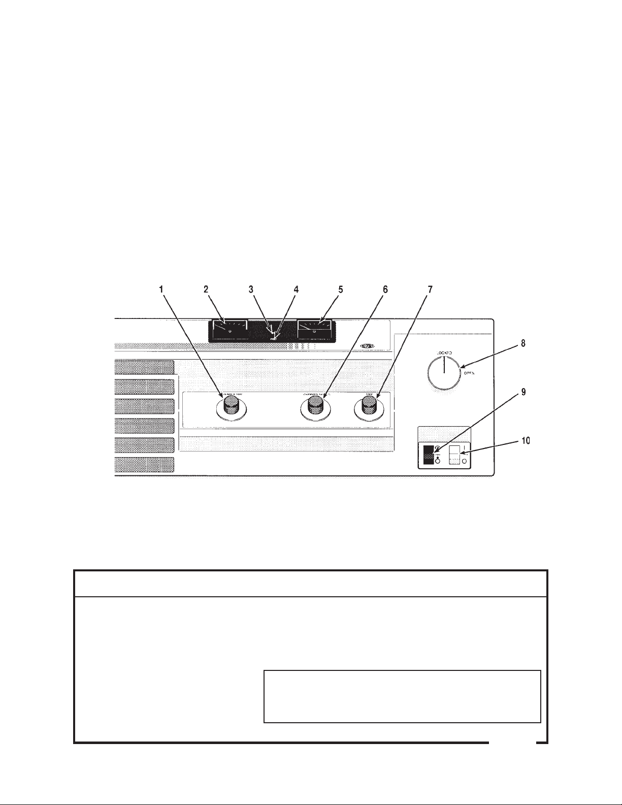
Figure 3-1 shows the location of operating controls and indicators. Table 3-1 lists them
by item number and describes their function.
Figu re 3 -1 . Con trols a nd Ind ica tors
Table 3-1. Controls and Indicators
(keyed to figure 3-1)
Item Na m e Fu n ction
1REV/MIN x 1000 Sets desired run speed. At full counterclockwise
position the speed control is turned offand the rotor
will not spin. (The settings on the dial indicate actu al
rotor speed.)
CAUTION
Continu ed operation of the centrifuge be-
low 6 0 0 rp m m a y d a m a ge th e s p eed con t rol.
(continued)
dial
Operation SORVALL®
Centrifuges
3-2
Table 3-1. Controls and Indicators (continued)
(keyed to figure 3-1)
Item Na m e Fu n ction
2REV/MIN x 1000 In d ica t es a ct u a l rot or s p eed from 0 to 6 0 00 rp m
±100 rpm.
3OPEN light* Lights at the end of the ru n to indicate that the door
may be opened.
4FAULT light* Lights when a rotor im balance occurs or when a
drive belt malfunction occurs. Centrifuge will not
restart until problem has been corrected.
4FAULT light* Lights when a rotor imbalance occu rs, when cham-
ber over or under temperature occurs, or when a
drive belt malfunction occurs. The centrifuge will
not restart until problem has been corrected.
5CHAMBER TEMP°C In d ica t es a ct u a l ch a m b er t em p er a tu r e from -2 0°C to
+40°C.
6CHAMBER TEMP°C Sets desired chamber temperature from -20°C to
+40°C.
7TIME dial Sets length of ru n time u p to 30 minu tes (or 35
minutes on 50 Hzinstruments). At
∞, sets indefinite
run time. The TIME d i a l a c t s a s a s t a r t s w i t c h t o b e g i n
centrifuge ru n.
8Doorreleaseknob WhentheknobisturnedtoOPEN it will relea se th e
door latches; when knob is turned to LOCKED it
engages the door latches.
9BRAKE switch When set to "", t h e cen t r ifu ge b r a k e s t o a p p r oxi-
mately 200 rpm at end ofrun then coasts to a stop.
Wh en s et t o " ", t h e c en t r ifu ge c oa s t s t o a s t op
with ou t brakin g.
10 POWER switch The power switch is an on/ off toggle switch that,
when set to "I" a p p lies p o we r t o t h e c en t r ifu ge .
Rotor Considerations
a. Rotor Temperature
An y t y p e o f c e n t r ifu ga t io n c r e a t e s a n in c r e a s e in r o t o r t e m p e r a t u r e . Th e in c r e a s e in
temperature is caused by many variables including ambient temperature, rotor speed,
len gth of th e ru n , a n d th e typ e of rotor.
*These messages are backlit, meaning that each message lights only when the condition that it represents exists.
(T6 0 0 0 B )
(R T6 0 0 0 B )
in d ica t or
(R T6 0 0 0 B on ly)
dial(RT6000Bonly)
in d ica t or

SORVALL®
Centrifuges Operation
3-3
Air flo w t h r o u gh t h e T6 0 0 0 B c e n t r ifu ge is d e s ign e d t o m in im ize in c r e a s e in r o t o r
temperature. Air enters through an opening in the center of the lid and exits through the
exhau st du ct at the top of the rotor chamber.
WARNING
Blocking the air flow entering and/or exiting the T6000B rotor chamber
will cause an increase in the temperature within the rotor chamber. The
temperature increase can temporarily distort the non-metal surfaces
allowing particles to exit the rotor chamber resulting in personal injury and/
or centrifuge damage should tube breakage or rotor failure occur.
Wh en ru n n in g tem pera tu re-sen s itive m a teria l we recom m en d th a t you d o a tria l ru n .
b. Rotor Installation, Loading and Balancing
Refer to th e rotor instru ction m anu al for loading an d balan cing procedu res as well as
in for m a tion rega r d in g th e s election a n d u s e of tu b es , b ott les , a n d a d a p ters .
WARNING
When loading the rotor, be sure not to exceed the maximum compartment
mass of the rotor (see Table 1-1 or the individual rotor instruction manual).
If maximum compartment mass is exceeded, maximum rotor speed must be
lowered as described on page 3-6, Reducing Speed for Rotor Compartment
Loads in Excess of Design Mass. Failure to do so can cause rotor failure
which could result in personal injury and/or centrifuge damage.
CAUTION
Do not operate the centrifuge without a rotor installed and properly
balanced. Also, when installing a rotor carefully place it on the centrifuge
drive spindle. The drive can be damaged if rotors are dropped onto it.
Precooling a Rotor in the RT6000B Centrifuge
For operation at temperatures other than ambient, the rotor and rotor chamber should
be precooled before the run using either of the precooling methods described.
a. Precooling a Rotor in the Centrifuge
1. Follow steps 1 through 6 of the operating instructions (pages 3-4 and 3-5).
2. Set the REV/MIN x 1000 dial to 1500 rpm.
Th e len gth of t im e it will ta ke to p recool a rotor will va ry d ep en d in g on th e tem p era tu re
selected, rotor weight, and rotor material.

Operation SORVALL®
Centrifuges
3-4
b. Precooling the Centrifuge Chamber Only
If th e rot or h a s b een p r ecooled ou ts id e of th e ch a m ber (e.g., in a r efriger a tor or cold room ),
the chamber should be precooled before the run.
1. With the chamber door closed, set the CHAMBER TEMP°C d ia l t o t h e t e m p e r a t u r e
desired.
2. When the chamber is cooled to the proper temperature, installthe precooled rotor
and begin the centrifuge run.
NOTE
To expedite cooling of the centrifuge chamber, run an empty rotor at
1500 rpm.
Running Hazardous Material
Because neither centrifuge chamber of the RT6000B or T6000B are designed for
biocontainment, some vapors or aerosols released from uncapped, leaking or broken
tubes may leak from the chamber during operation. Once a run is completed and the
chamber door is opened, the vapors or aerosols which have concentrated in the chamber
will be released into the laboratory area. For this reason, when materials which are
pathogenic, toxic, or otherwise hazardous in nature are to be run, the centrifuge should
be placed in a biohazard safety enclosure and operated using all appropriate safety
precautions. Observe the WARNING found on the Safety Information Page.
Use appropriate decon tam in ation procedu res sh ou ld exposu re to an y hazardou s m aterial
occu r. See Ch apter 4 for th e procedu re to follow if a cen trifu ge or rotor th at has been u sed
with a h azardou s m aterial m u st be retu rn ed to ou r service facilities for repair.
Operation
To perform the run:
1. Set the POWER switch to "I", a n d t u r n t h e TIME dial off. (The fan will turn on and
continu e to operate whenever the POWER switch is in the on position).
NOTES
RT6000B Centrifuges ONLY:
The FAULT light may come on when the power is turned on with the door
closed. The light will go off when the door is opened.
It is recommended that the chamber door be kept closed when the
centrifuge is not in use to prevent condensation from forming in the rotor
chamber.

SORVALL®
Centrifuges Operation
3-5
2. When the OPEN ligh t c om es on , t u r n t h e d oor r ele a s e k n ob t o t h e OPEN p os it ion , a n d
lift th e ch a m ber door u p.
3. Install the rotor on the drive shaft and close the door. Turn the door release knob to
the LOCKED position (the door latches will engage).
CAUTION
Be sure the rotor is properly balanced and seated on the drive spindle. See
rotor instruction manual.
4. RT6000B only: Set the CHAMBER TEMP°C dial to the ru n temperatu re desired.
5. Set the BRAKE switch to " " if b r a k in g is d e s ir ed .
6. Set the TIME dial to the run time desired.
7. Set the REV/MIN x 1000 dial to the desired run speed.
NOTE
The settings on the REV/MIN x 1000 dial indicate actual rotor speed. Verify
the rotor speed by checking the REV/MIN x 1000 indicator.
A zero speed switch is incorporated in the REV/MIN x 1000 dial. This switch
prevents rotation of the rotor if the door is locked and the timer is on.
At t h e e n d o f t h e r u n r e m o ve t h e r o t o r a s d e s c r ib e d b e lo w .
WARNING
Always check that the rotor has stopped spinning before opening the
chamber door. Do not open the door while the rotor is still in motion; to
do so can result in possible injury.
To remove the rotor:
1. Leave the POWER switch set to "I".
2. If the TIME dial is set to ∞, tu rn it off.
3. When the OPEN ligh t com es on , tu r n t h e d oor r elea s e k n ob to OPEN p os ition a n d lift
the chamber door up.
4. Remove the rotor, close the chamber door, and set the POWER switch to "0".

Operation SORVALL®
Centrifuges
3-6
Emergency Sample Recovery
If th e m a in p ower sh u ts off b eca u s e of a p ower fa ilu r e or s ys tem m a lfu n ct ion wh ile th e rotor
is s pin n in g, th e ch a m ber d oor will n ot open . A m ech a n ica l overrid e is p rovided to a llow
sample recovery in the case of an emergency.
WARNING
This procedure is included for emergency sample recovery only and
should never be used for any purpose other than those explained in this
section.
When the main power shuts off, the brake will not operate. Wait until the
rotor stops spinning before using the mechanical override.
Th e m ech a n ica l overrid e loop is loca ted u n der th e righ t, fron t cor n er of th e cen trifu ge a s
shown in figure 3-2. To operate the override, insert a screwdriver or similar object into the
metal loop and pull down. Turn the door release knob to the OPEN position an d lift th e
chamber door up.
Figu re 3 -2 . Loca tion of Mech a nica l Overrid e Loop
NOTE
Leave a clearance area around the lower right corner of the centrifuge to
prevent obstruction of the mechanical override.
Reducing Speed for Rotor Compartment Loads
in Excess of Design Mass
Th er e is a m a xim u m a llowa b le com p a rt m en t m a s s es ta b lis h ed for ea ch cen t rifu ge r otor.

SORVALL®
Centrifuges Operation
3-7
To preven t rotor failu r e, th e tota l con ten ts of a n y com pa rtm en t, in clu din g s pecim en ,
tubes, cover, and adapters (if used), must not exceed the figure given on page 1-2 unless
rotor speed is reduced proportionately.
Strict adherence to the maximum allowable compartment mass or reduced speed is
required to prevent rotor failure. Observe WARNING on the Safety Information Page
in front of this m anual.
Th e r otor s peed is redu ced in p rop or tion to th e s qu a re of th e ra tio for t h e m a xim u m
allowable compartment mass to the actual compartment mass (including specimen,
tubes, covers, and adapters). Ifthe compartment mass is more than that specified for the
rotor, the reduced speed can be determined by using the formula given below.
Reduced Rotor Speed = Maximum Rotor Speed x
3-7/3-8
√Maximum Compartment Mass
Actual Compartment Mass

SORVALL®
Centrifuges Maintenance
4-1
Chapter 4
MAINTENANCE
Th is ch a pter des crib es r ou tin e m a in ten a n ce p roced u res th a t you s h ou ld p er for m on a
regular basis. As the user, it is your responsibility to make certain that these procedures
are followed when necessary. Also, to keep your centrifuge in good working condition and
ensu re accu rate test resu lts, we recommend that, in addition to these routine procedures,
you h a ve th e s peed con trol, tim er, rotor im bala n ce detector a n d tem pera tu re con trol
checked periodically by a Du Pont Service Representative or other qu alified service
personnel because occasionally, these controls may need to be recalibrated. If further
service is needed, contact your local representative for SORVALL
®Produ cts.
WARNING
Because of the high voltages in this centrifuge, only personnel trained in
electronics should test or repair the electrical circuits.
If hazardous materials have been processed in the centrifuge, take all
necessary precautions when cleaning or servicing the centrifuge to avoid
personal exposure to contamination.
Inspection and Cleaning
a. Inspection
In s pect t h e cen trifu ge ea ch week for s ign s of wea r, en cru sted b iologica l d ep os its , a n d
gen eral clea n lin es s. Follow th e clea n in g procedu res des cribed below wh en n eces sary.
b. Cleaning
Rotor Chamber
Th e r ot or ch a m ber s h ou ld b e k ep t clea n a n d wip ed d ry. Wa sh th e rotor ch a m ber with
a mild,nonalkaline dishwashingliquid,then rinse and drywith a soft absorbent cloth.
Use 70% eth anol to disinfect th e rotor ch am ber or a 2% glu taraldeh yde solu tion to
sterilize it. For general radioactive decontamination, use a solution of equal parts of
70% ethanol, 10% SDS, and water. Follow this with ethanol rinses then deionized
water rinses. Dry with a soft absorben t cloth. Dispose of all wash solu tions in proper
radioactive waste containers. Read the CAUTION on the next page.

Maintenance SORVALL®
Centrifuges
4-2
CAUTION
Chlorides are extremely harmful to aluminum alloy rotors and can cause
stress corrosion cracking. Therefore, if chlorides are used to disinfect the
chamber, be sure to rinse the chamber thoroughly with water to remove all
of the chloride cleanser.
Periodically defrost the rotor chamber of the RT6000B to maintain efficient cooling.
Th e ch a m ber ca n b e d efros ted b y eit h er lea vin g th e d oor open wit h th e p ower off u n til
the frost melts, or by running a rotor for approximately five minutes at 40°C. When
the chamber has been completely defrosted, wipe the chamber dry.
Drive Spindle
Before each run, wipe the spindle with a soft cloth before a rotor is installed to reduce
the chance of the rotor sticking to the spindle. To keep the surface of the spindle
smooth, polish occasionally with #400 Emery cloth. Always wipe the spindle clean
after polishing.
Cabinet
Clean the enameled cabinet panels with a hou sehold wax cleaner. Use a mild,
nonalkaline detergent and water to clean the centrifuge.
Chamber Door
Clean the chamber door with a soft, wet cloth and soapy water. Avoid using abrasive
materials (for example, dry papertowels)and organic solvents (for example, acetone)
on th e dry su rface.
Condenser Fins
To m a in ta in th e efficien cy of th e R T6000B r efrigera tion s ystem , k eep th e con den ser
fin s (loca t ed in th e fr on t of t h e cen t r ifu ge) fr ee of d ir t a n d d u s t . Clea n t h e fin s wit h
a brush or vacuum cleaner at one to three month intervals.
c. FAULT System Check
To ch eck th e fu n ction of th e FAULT system, move the drive spindle back and forth to
simulate a rotor imbalance. This should cause the FAULT indicator to light.
REV/MIN x 1000 Indicator Adjustment (figure 4-1)
With t h e POWER s w it c h s e t t o "0", u s e a s cr ewd r ive r a n d a d ju s t t h e zer o a d ju s t m e n t s cr ew
until the pointer reads 0.
This manual suits for next models
1
Table of contents
Other Sorvall Laboratory Equipment manuals


Popular Laboratory Equipment manuals by other brands


Molecular Devices
Molecular Devices SpectraMax L INSTALLATION PROCEDURE

Steinberg Systems
Steinberg Systems SBS-AC-2300 user manual

Hanatek
Hanatek MFI 4050 operating manual

Barnstead International
Barnstead International General Purpose Aquabath 18002 manual

Fisher Scientific
Fisher Scientific 280A Installation and operating instructions

Renfert
Renfert Catalyser 2300-0001 instruction manual