VIA NV-SCHIENENSYSTEM D
BRUCK GMBH & CO.KG
INDUSTRIESTR. 22 • 44628 HERNE
internet http://www.bruck.de
GEBRAUCHSANLEITUNG D
TECHNISCHE DATEN
Systemspannung 12 V SELV
max. Strom 25 A
max Belastung 300 W
Anschlußleitung 4 - 6 qmm
Schutzklasse
LIEFERUMFANG
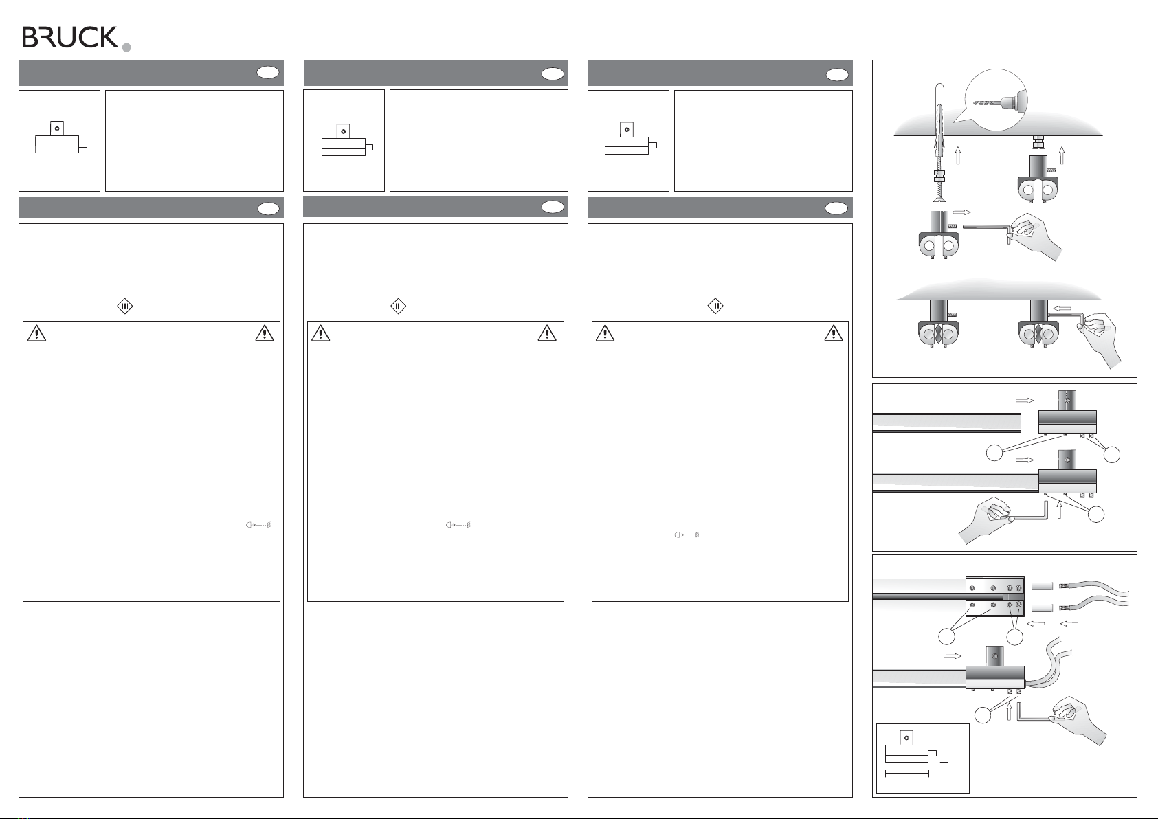
1 Wandbefestigung mit Einspeisung, komplett,
4 Aderendhülsen, 2 Innensechskantschlüssel,
1 Ersatzschraube, Montagematerial
2 Endkappen
AAcchhttuunngg!!Bei starker Erwärmung Schrauben CCund DDfest
nachziehen! 14 Tage nach Montageende sollten
alle Befestigungsschrauben kontrolliert bzw.
leicht nachgezogen werden.
HHiinnwweeiiss::Als Anschlußleitung empfehlen wir unser Produkt
Anschlußleitung, 2x4qmm / 2x6qmm flexibel,
transparent isoliert. ( Art.-Nr.: 150 118 / 150 121)
EINSPEISUNG C/W END VIA
ART.-NO. 160 514
VIA LV TRACK SYSTEM
241102023D
GB
TECHNICAL DATA
System voltage 12 V SELV
max. current 25 A
max. load 300 A
Connecting line 4 – 6 qmm
Protection class
DELIVERY SCOPE
1 wall fastener with feed, complete
4 multicore cable ends, 2 hexagonal recess wrenches,
1 replacement screw, mounting material
2 end caps
AAtttteennttiioonn!!In case of heating up, strongly retighten the
screws CCand DD! 14 days after completion
of assembly, all fastening screws should be
checked respectively lightly retightened.
RReemmaarrkk::As connecting line, we recommend our product
connecting line, 2x4 qmm / 2x6 qmm flexible,
transparent insulation (item no. 150 118 / 150 121)
VIA SYSTÈME À RAIL BT
MODE D´EMPLOI
F
F
CARACTERISTIQUES TECHNIQUES
Tension du système 12 V SELV
Courant max. 25 A
Charge max. 300 W
Câble de raccordement 4 – 6 qmm
classe de protection
VOLUME DE LIVRAISON
1 fixation murale avec alimentation complète. 4 douilles de con-
tact ,2 clés allène six pans, 1 vis de rechange, matériel de montage
2 capuchons
AAtttteennttiioonn!!Resserrez les vis CCet DDlors d’un important
échauffement. 14 jours après la fin du montage,
toutes les vis doivent être contrôlées ou être
légèrement resserrées.
RReemmaarrqquuee::Comme câble de raccordement, nous vous
conseillons notre produit câble de raccordement:
2x4 qmm / 2x6 qmm flexible, transparent isolé.
(Art.-No.:150 178 / 150 121).
POWER FEED C/W END VIA
ART.-NO. 160 514
ALIMENTATION C/W END VIA
ART.-NO. 160 514
USER MANUAL GB
Ø 6mm
CD
D
D
C
C
ALLGEMEINE SICHERHEITSHINWEISE
1. Montage und Anschluß des Systems nur durch Fachpersonal
(Elektriker).
2. Bei allen Arbeiten an System und Leuchten AAnnllaaggee
ssppaannnnuunnggssffrreeiisscchhaalltteenn!!!!
3. Nicht zur Installation in Feuchträumen geeignet.
4. Bei der Montage des VIA-Systems dürfen nur
VIA-Systembauteile verwendet werden.
5. AAcchhttuunngg,,GGeeffaahhrrdduurrcchhSSttrroommsscchhllaagg!!!!
System und Leuchten nniieemmaallssohne Trafo direkt an die
NNeettzzssppaannnnuunng
ganschließen!
6. Es liegt in der Verantwortung des Benutzers, die elektrische,
mechanische und thermische Verträglichkeit zwischen dem
System und den daran angebrachten Leuchten
sicherzustellen.
7. VVoorrssiicchhtt!!Leuchte und Leuchtmittel werden in Betrieb heiß.
8. Den angegebenen Mindestabstand der Leuchtmittel zu
brennbaren Gegenständen beachten! (siehe Leuchte )
9. AAcchhttuunngg::Zur Verminderung der Gefahr von Überhit-
zung und Feuer keine Leiter überbrücken.
10. Kein Garantieanspruch bei eigenmächtigen Veränderungen
und oder unsachgemäßer Benutzung!
GENERAL REMARKS ON SAFETY
1. Assembly and connection of the system only by specialist
personnel (electrician).
2. SSwwiittcchhooffffppoowweerrttootthheessyysstteemmfor all work on the system
and on lamps!!
3. Not suitable for installation in wet rooms.
4. For assembly of the VIA system, only VIA system compo-
nents must be used.
5. AAtttteennttiioonn,,eelleeccttrriiccsshhoocckkhhaazzaarrdd!!!!NNeevveerrconnect the system
and lamps without transformer directly to tthheemmaaiinnss
vvoollttaaggee!
!!!
6. It is within the responsibility of the user to ensure the
electrical, mechanical and thermal compatibility between
the system and lamps mounted to it.
7. TTaakkeeccaarree!!Lamp and illuminant become hot during
operation.
8. Observe the stated minimum distance of the illuminants to
flammable objects! ( see lamp )
9. AAtttteennttiioonn::In order to minimise the risk of overheating
or fire do not bypass any conductors.
10. No warranty claim in case of unauthorized modifications
and / or improper use!
CONSIGNE DE SECURITE GENERALES
1. Le montage et le raccordement des luminaires ne doivent
se faire que par du personnel spécialisé (électricien)
2. Avant d’effectuer tout travail sur le système et les
luminaires mmeettttrreell’’iinnssttaallllaattiioonnhhoorrsstteennssiioonn
3. N’est pas approprié à être installé dans des pièces humides
4. Lors du montage du Système VIA n’utiliser que les
composants de la gamme VIA.
5. AAtttteennttiioonnddaannggeerrdd’’éélleeccttrrooccuuttiioonn!!!!NNeejjaammaaiissraccorder le
système ou les luminaires directement sur le réseau sans le
transformateur !
6. L’utilisateur est resposnsable d’assurer la compatibilité
électrique, mécanique et thermique entre le système et les
luminaires qui s’y rapportent.
7. AAtttteenntti
ioonn!!Les luminaires et les lampes sont brûlantes lors
de leur utilisation.
8. Veiller à respecter l’intervalle minimum indiqué des lampes
par rapport à des objets inflammables.
(voir luminaires )
9. AAtttteennttiioonn::afin de minimiser les risques de surchauffe et
d´incendie, ne pas court-circuiter les conducteurs.
10. Nous ne donnons aucune garantie lors de modifications
effectuées sur l’installation ou lors d’une utilisation
inadéquate