Bruck 160528 User manual

VIA NV-SCHIENENSYSTEM D
BRUCK GMBH & CO.KG
INDUSTRIESTR. 22 • 44628 HERNE
internet http://www.bruck.de
GEBRAUCHSANLEITUNG D
TECHNISCHE DATEN
Beschreibung: Mitteneinspeisung für VIA-Schienen
an Wand und Decke
Systemspannung: 12 V SELV
max. Belastung: 300 W
Material: Messing-Druckguß
Oberfläche: verchromt / vergoldet / matt-verchromt
bronze
LIEFERUMFANG
1 Mitteneinspeisung, komplett 2teilig, 2 Endkappen
WWiicchhttiigg! Die Einspeisung kann an beliebiger Stelle der
Schiene nachträglich angebracht werden. Um den Spannungsfall
zu vermindern, empfiehlt es sich jedoch, den Ort der Einspeisung
möglichst mittig im System zu wählen. Anschlußleitung
min. 4 mm², max. 6 mm², Kupfer isoliert
- Anschlußleitung 10mm abisolieren (s. Hinweis),
- Schrauben AAlösen, Einspeisung von der Seite auf die
Schiene schieben. Schrauben AAgut anziehen
- Schrauben BBlösen, Anschlußleitung mit Aderendhülse
versehen in Bolzen CCeinschieben und Schrauben BB
wieder gut festziehen.
AAcchhttuunngg! Bei starker Erwärmung alle Schrauben fest nachziehen!
14 Tage nach Montageende sollten alle Befestigungsschrauben
kontrolliert bzw. leicht nachgezogen werden.
HHiinnwweeiiss: Als Anschlußleitung empfehlen wir unser Produkt
Anschlußleitung, 2 x 4 mm² flexibel, transparent isoliert.
(Art.-Nr.: 150 118 / ID-Nr.: 124 529).
EINSPEISUNG VIA
ART.-NO. 160 528
VIA LV TRACK SYSTEM
USER MANUAL
151102993I
GB
GB
TECHNICAL DATA
Description: Ceiling power feed for VIA tracks on the
wall and on the ceiling.
System voltage: 12 V SELV
Maximum charge: 300 W
Material: brass pressure founding
Surface: chrome-plated / gold-plated / mat chrome-plated
bronze
DELIVERY SCOPE
1 central alimentation, complete, one part, 2 end caps
IImmppoorrttaanntt!!The power feed can be built into the track at any
place and at any time later on. But we recommend to choose the
position of the alimentation as centric as possible in the system in
order to avoid a loss of voltage. Connection line, insulated with
copper, minimum 4 qmm, maximum 6 qmm
- Remove 10 mm of the insulation of the connetion line. (See
indication!)
- Loosen the screws AA, push the power feed laterally on to the
track. Fix the screws AAfirmly.
- Loosen the screws BB. Push the connecting line into the bolt CC.
AAtttteennttiioonn!!In case of strong heating, fasten all screws again
firmly! 14 days after finishing the mounting all fixing screws
should be checked or eventually fastened again slightly.
IImmppoorrttaanntt!!We recommend our product ‘connection line’ as
conducter of connection, 2 x 4 qmm flexible, transparent,
insulated.
(Art.-No.: 150 118 / EAN-No.: 124 529).
VIA SYSTÈME À RAIL BT
MODE D´EMPLOI
F
F
CARACTÉRISTIQUES TECHNIQUES
Descripcion: Alimentation pour lignes VIA au mur et au
plafond.
Voltage de système: 12 V SELV
Charge max.: 300 W
Matériaux: fusion à presion de laiton
Surface: cromé / doré / mat-cromé / bronze
VOLUME DE LIVRAISON
1 alimentation centrale, complète, une partie, 2 capuchons
IImmppoorrttaanntt!!Plus tard, l’alimentation peut être incorporée à la
ligne, à quelconque lieu et à quelconque moment. Mais nous
recommandons d’élégir la position de l’alimentation la plus
centrale que possible au système pour éviter une perte de voltage.
Ligne de connexion, isolée avec cuivre, min. 4 mm², max. 6 mm².
- Enlever 10 mm de l’isolation de la ligne de connexion. (Voir
l’indication!)
- Dévisser les vis AA, mettre l’alimentation latéralement à la ligne.
Fixer les vis AAtrès fort.
- Dévisser les vis BB. Passer la ligne de connexion à la cheville CC
AAtttteennttiioonn!!Dans le cas d’haute chaleur, fixer encore une fois
très fort toutes les vis! 14 jours depuis de terminer le montage,
tous les vis de fixation devraient être contrôlées ou éventuelle-
ment légèrement serrées de nouveau.
IImmppoorrttaanntt!!Recommandons notre produit ‘ligne de connexion’
comme conducteur de connexion, 2 x 4 mm² flexible,
transparent, isolé. (Art.-No.: 150 118 / EAN-No.: 124 529).
1
A
1 2
POWER FEED VIA
ART.-NO. 160 528
ALIMENTATION VIA
ART.-NO. 160 528
1 2 1 2
A
2
C
B
A
26,5mm
30mm
ALLGEMEINE SICHERHEITSHINWEISE
1. Montage und Anschluß des Systems nur durch Fachpersonal
(Elektriker).
2. Bei allen Arbeiten an System und Leuchten AAnnllaaggee
ssppaannnnuunnggssffrreeiisscchhaalltteenn!!!!
3. Nicht zur Installation in Feuchträumen geeignet.
4. Bei der Montage des VIA-Systems dürfen nur
VIA-Systembauteile verwendet werden.
5. AAcchhttuunngg,,GGeeffaahhrrdduurrcchhSSttrroommsscchhllaagg!!!!
System und Leuchten nniieemmaallssohne Trafo direkt an die
NNeettzzssppaannnnuunng
ganschließen!
6. Es liegt in der Verantwortung des Benutzers, die elektrische,
mechanische und thermische Verträglichkeit zwischen dem
System und den daran angebrachten Leuchten
sicherzustellen.
7. VVoorrssiicchhtt!!Leuchte und Leuchtmittel werden in Betrieb heiß.
8. Den angegebenen Mindestabstand der Leuchtmittel zu
brennbaren Gegenständen beachten! (siehe Leuchte )
9. AAcchhttuunngg::Zur Verminderung der Gefahr von Überhit-
zung und Feuer keine Leiter überbrücken.
10. Kein Garantieanspruch bei eigenmächtigen Veränderungen
und oder unsachgemäßer Benutzung!
GENERAL REMARKS ON SAFETY
1. Assembly and connection of the system only by specialist
personnel (electrician).
2. SSwwiittcchhooffffppoowweerrttootthheessyysstteemmfor all work on the system
and on lamps!!
3. Not suitable for installation in wet rooms.
4. For assembly of the VIA system, only VIA system compo-
nents must be used.
5. AAtttteennttiioonn,,eelleeccttrriiccsshhoocckkhhaazzaarrdd!!!!NNeevveerrconnect the system
and lamps without transformer directly to tthheemmaaiinnss
vvoollttaaggee!
!!!
6. It is within the responsibility of the user to ensure the
electrical, mechanical and thermal compatibility between
the system and lamps mounted to it.
7. TTaakkeeccaarree!!Lamp and illuminant become hot during
operation.
8. Observe the stated minimum distance of the illuminants to
flammable objects! ( see lamp )
9. AAtttteennttiioonn::In order to minimise the risk of overheating
or fire do not bypass any conductors.
10. No warranty claim in case of unauthorized modifications
and / or improper use!
CONSIGNE DE SECURITE GENERALES
1. Le montage et le raccordement des luminaires ne doivent
se faire que par du personnel spécialisé (électricien)
2. Avant d’effectuer tout travail sur le système et les
luminaires mmeettttrreell’’iinnssttaallllaattiioonnhhoorrsstteennssiioonn
3. N’est pas approprié à être installé dans des pièces humides
4. Lors du montage du Système VIA n’utiliser que les
composants de la gamme VIA.
5. AAtttteennttiioonnddaannggeerrdd’’éélleeccttrrooccuuttiioonn!!!!NNeejjaammaaiissraccorder le
système ou les luminaires directement sur le réseau sans le
transformateur !
6. L’utilisateur est resposnsable d’assurer la compatibilité
électrique, mécanique et thermique entre le système et les
luminaires qui s’y rapportent.
7. AAtttteenntti
ioonn!!Les luminaires et les lampes sont brûlantes lors
de leur utilisation.
8. Veiller à respecter l’intervalle minimum indiqué des lampes
par rapport à des objets inflammables. (voir luminaires )
9. AAtttteennttiioonn::afin de minimiser les risques de surchauffe et
d´incendie, ne pas court-circuiter les conducteurs.
10. Nous ne donnons aucune garantie lors de modifications
effectuées sur l’installation ou lors d’une utilisation inadéquate

BRUCK GMBH & CO.KG
INDUSTRIESTR. 22 • 44628 HERNE
internet http://www.bruck.de
VIA SISTEMA DE RAILES DE BT EVIA SISTEMA A BINARIO A BV IPLANUNGSHILFE
PLANNING AIDS
ASSISTANCE DE PLANNING
ASISTENCIA DE PLANIFICACIÓN
ASSISTENZA ALLA PIANIFICAZIONE
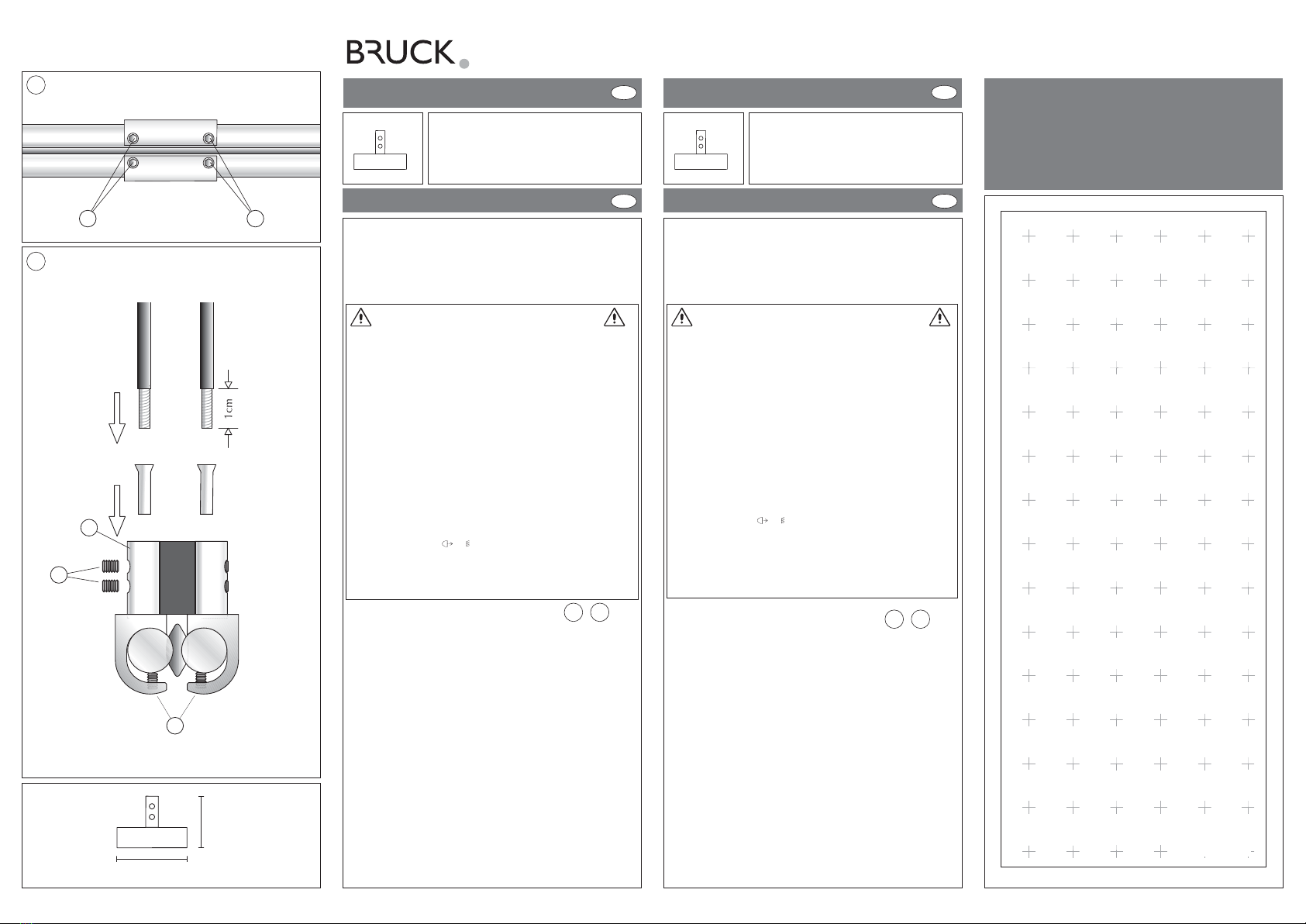
1 cm = 1 m
ALIMENTACIÓN VIA
ART.-NO. 160 528
DATI TECNICI
Descrizione: Alimentazione per linee VIA alla parete ed al soffitto
Voltaggio di sistema: 12 V SELV
Carica massima: 300 W
Materiale: ottone di pressione colata
Superficie: cromato / dorato / cromo opaco / bronzo
VOLUME DELLA FORNITURA
1 alimentazione central, completa, una parte
2 terminali
IImmppoorrttaannttee!!Più tardi, l’alimentazione può esser incorporata
nella linea, a qualunque luogo ed a qualunque momento. Ma rac-
comandiamo di eleggere la posizione dell’alimentazione più cen-
trale che possibile al sistema per evitare una perdita di
voltaggio. Linea di connessione, isolata con, al minimo: 4 mm², al
massimo: 6 mm².
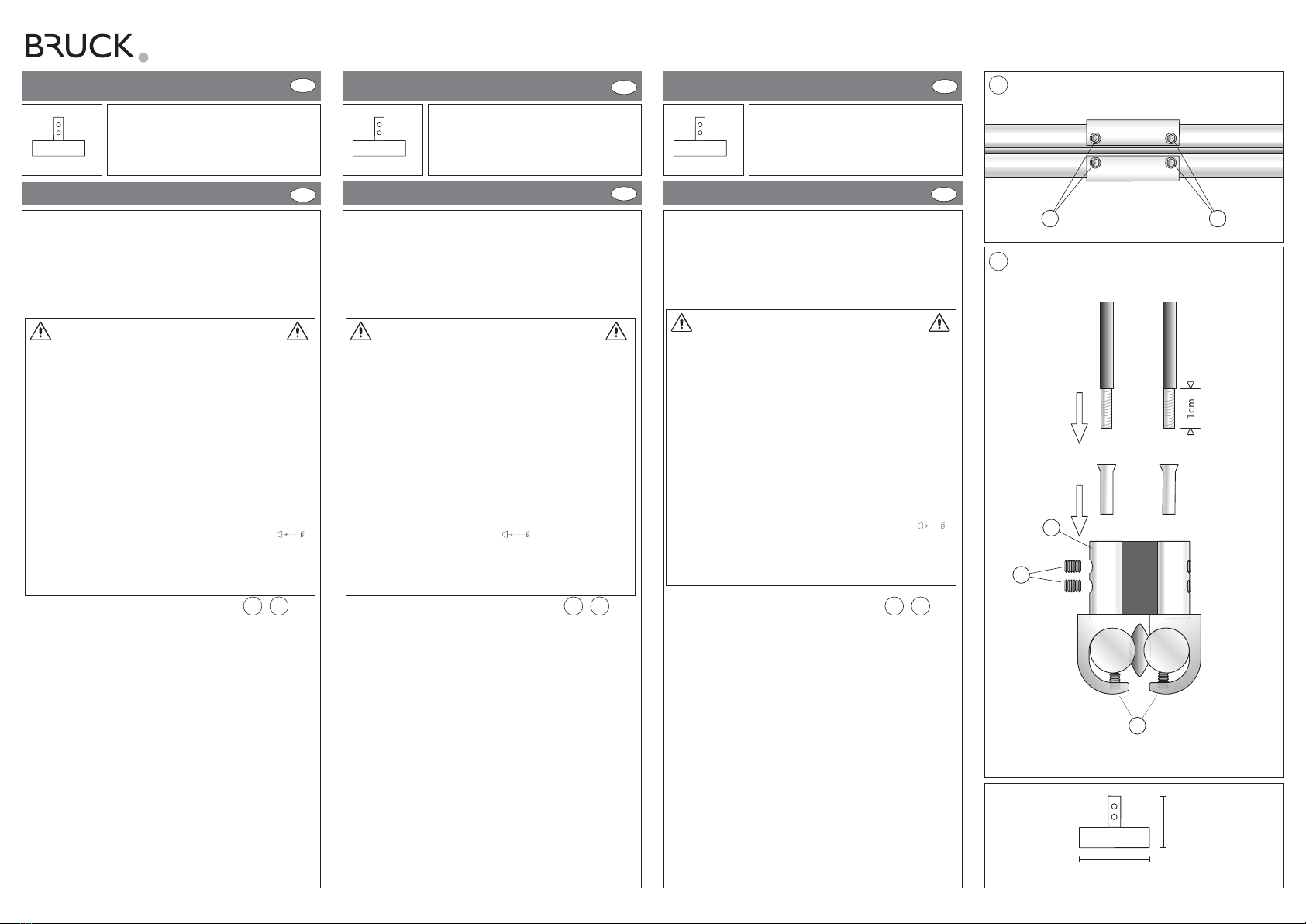
- Rimuovere 10 mm dell’isolazione della linea di connessione.(Vedasi
l’indicazione!)
- Allentare le viti AA, mettere l’alimentazione lateralmente alla
linea. Fissare le viti AAben fermo.
- Allentare le viti BB. Passare la linea di connessione al perno CC
AAtttteennzziioonnee!!Nel caso di alto calore, fissare ancora una volta
ben forte tutte le viti! 14 giorni dopo terminare il montaggio, tutte
le viti di fissaggio dovrebbero controllate od eventualmente serrate
leggereamente di nuovo.
IImmppoorrttaannttee!!Raccomandiamo il nostro prodotto ‘linea di con-
nessione’ come conduttore di connessione, 2 x 4 mm² flessibile,
transparente, isolato. (Art.-No.: 150 118 / EAN-No.: 124 529).
INSTRUCCIONES DE EMPLEO E
DATOS TÉCNICOS
Descripción: Alimentación para líneas VIA en la pared y en el techo
Voltaje de sistem: 12 V SELV
Carga máxima: 300 W
Material: colado de presión de latón
Superficie: cromo / dorado / cromo mate / bronce
VOLUMEN DE SUMINISTRO
1 alimentación central, completa, una parte,
2 capuchónes finales
¡¡IImmppoorrttaannttee!!La alimentación puede incorporarse en la línea
más tarde a cualquier punto y a cualquier momento. Pero
recomendamos elegir la posición de la alimentación lo más
céntrica posible en el sistema para evitar una pérdida de voltaje.
Línea de conexión, isolada con cobre, min. 4 mm², max. 6 mm².
- Remover 10 mm de la isolación de la línea de conexión.
(¡Véase la indicación!) Pasar la manguera contractante
ligeramente sobre el cable.
- Desatornillar los tornillos AA, poner la alimentación
lateralmente en la línea. Fijar los tornillos AAfuerte.
- Desatornillar los tornillos BB. Pasar la línea de conexión en el
perno CCe isolarla eventualmente con la manguera contractante.
¡¡AAtteenncciióónn!!En el caso de fuerte calor, fijar otra vez todos los
tornillos fuerte! 14 días después de terminar el montaje, todos los
tornillos de fijación deberían ser controlados o eventualmente ser
serrados otra vez ligeramente.
¡¡IImmppoorrttaannttee!!Recomendamos nuestro producto ‘línea de
conexión’ como conductor de conexión, 2 x 4 mm² flexible,
transparente, isolado. (Art.-No.: 150 118 / EAN-No.: 124 529).
ISTRUZIONI PER L´USO I
ALIMENTAZIONE VIA
ART.-NO. 160 528
1 2 1 2
AVVERTENZE GENERALI PER LA SICUREZZA
1. Il montaggio e il collegamento del sistema vanno effettuati
esclusivamente da personale specializzato (elettricista).
2. Per tutti i lavori sul sistema e sulle lampade eelliimmiinnaarreellaa
tteennssiioonneeddaallll’’iimmppiiaannttoo!!
3. Non adatto per l’installazione in locali umidi.
4. Per il montaggio del sistema VIA vanno utilizzati
esclusivamente componenti di sistema VIA.
5. AAtttteennzziioonnee,,ppeerriiccoollooddiissccoosssseeddiiccoorrrreennttee!!!!Non
collegare il sistema e la lampada mmaaiidirettamente alla
tte
ennssiioonneeddeellllaarreetteesenza trasformatore!
6. L’utente è responsabile di assicurare la tollerabilità elettrica,
meccanica e termica tra il sistema e le lampade applicate.
7. AAtttteennzziioonnee!!La lampada ed il mezzo illuminante scottano
quando funzionanti.
8. Osservare la distanza minima indicata del mezzo
illuminante da oggetti combustibili!
( vedi lampada )
9. AAtttteennzziioonnee::al fine di ridurre il rischio di surriscaldamen-
to e incendio, non cavallottare i conduttori.
10. Nessun diritto di garanzia in caso di modifiche apportate di
propria iniziativa e / o di utilizzo inappropriato!
INDICACIONES GENERALES DE SEGURIDAD
1. El montaje y la conexión del sistema deben ser llevados a
cabo solamente por personal técnico (electricistas).
2. ¡En todos los trabajos a llevar a cabo en el sistema y las
lámparas ha de mantenerse la iinnssttaallaacciióónnlliibbrreeddeetteennssiióónn!!
3. El sistema no es apropiado para la instalación en locales
húmedos.
4. En el montaje del sistema VIA solamente deben emplearse
piezas constructivas del sistema VIA.
5. ¡¡AAtteenncciióónnppeelliiggrrooddeeeelleeccttrrooccuucciióónn!!¡El sistema y las
lámparas no deben conectarse nnuunnccaadirectamente a la
tteennssiióónnddeerreeddsin transformador!
6. Es responsabilidad del usuario asegurar la compatibilidad
eléctrica, mecánica y térmica entre el sistema y las lámparas
empleadas en él.
7. ¡¡CCuuiiddaaddoo!!Las lámparas y las bombillas o reflectores se
calientan durante el funcionamiento.
8. ¡Ha de observarse la distancia mínima indicada de las
bombillas o reflectores respecto de los objetos combustibles!
( véase la lámpara ).
9. AAtteenncciióónn::no puentee ningún conductor eléctrico para así
disminuir el riesgo de sobrecalentamiento e incendio.
10. Se pierden las reivindicaciones de garantía al llevar modifi
caciones a cabo por propia cuenta y / o empleo incorrecto!
1
AA
2
C
B
A
26,5mm
30mm
Other Bruck Work Light manuals
Popular Work Light manuals by other brands

Bayco
Bayco NIGHTSTICK Dual-Light Xtreme Lumens... instruction manual

Havis-Shields
Havis-Shields Magnafire 3000 brochure

REV Ritter
REV Ritter ZZ-812-SMD Assembly and operating instructions

LED's work
LED's work 700318 operating manual

REV Ritter
REV Ritter FLEX POWER 10 Assembly and operating instructions

Philips
Philips Xitanium Xitanium Brochure & specs