Brultech Greeneye Monitor User manual

Brultech Research Inc
October 7, 2012
www.brultech.com Copyright © 2012 Brultech Research Inc. All rights reserved.
1
GreenEye Monitor™Manual
(Preliminary/Incomplete)
Energy Consumption Monitor
With Pulse Counter and Temperature Sensing Inputs

Brultech Research Inc
October 7, 2012
www.brultech.com Copyright © 2012 Brultech Research Inc. All rights reserved.
2
Introduction........................................................................................................................................................................... 4
Overview ................................................................................................................................................................................... 4
The sensors................................................................................................................................................................................ 6
Current Sensors .................................................................................................................................................................... 6
Voltage Sensors .................................................................................................................................................................... 6
Pulse Output Devices............................................................................................................................................................ 6
Temperature Sensors ........................................................................................................................................................... 6
Communication ......................................................................................................................................................................... 7
Where to Start ....................................................................................................................................................................... 8
Read and UNDERSTAND the safety information ....................................................................................................................... 8
Power up and establish communication before installing ........................................................................................................ 8
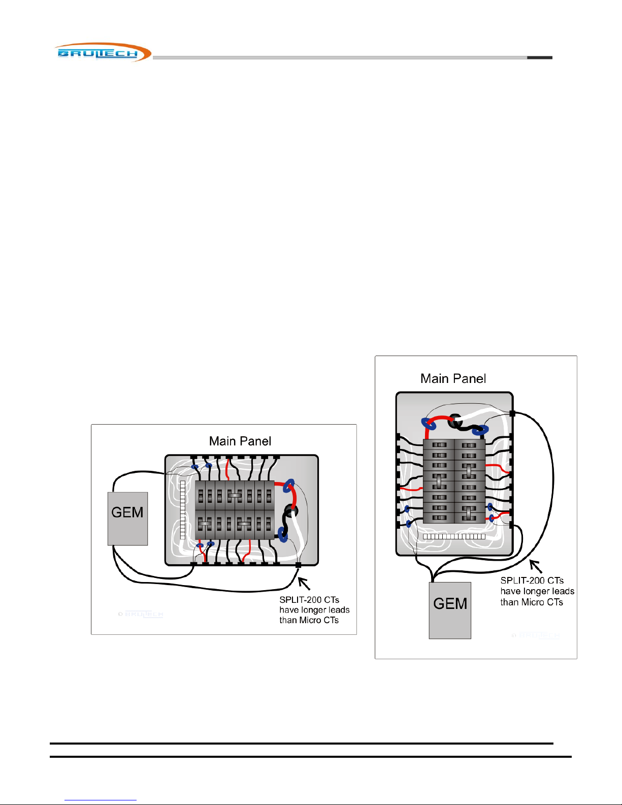
Plan the mounting location for the monitor, taking into consideration the CT lead length ..................................................... 8
Important Safety Information .............................................................................................................................................. 10
Compliance .......................................................................................................................................................................... 11
Overview / Layout ............................................................................................................................................................... 12
(1) CT Connection Terminals ................................................................................................................................................... 13
(2) Pulse Counter Inputs .......................................................................................................................................................... 13
(3) Potential Transformer (PT) Input ....................................................................................................................................... 14
(4) Alternate Potential Transformer (PT) And 5VDC Supply Input .......................................................................................... 14
(5) GEM Power Supply Input ................................................................................................................................................... 14
(6) Power Supply Access Terminals ......................................................................................................................................... 14
(7) “1-Wire” Bus and RS-232 Ground Terminal ....................................................................................................................... 14
(8) RS-232 Connection............................................................................................................................................................. 14
(9) Optional COM Module Header .......................................................................................................................................... 14
(10) Optional WiFi Module ...................................................................................................................................................... 15
(11) XBee® Module Socket ...................................................................................................................................................... 15
(12) Battery Holder.................................................................................................................................................................. 15
(13) System and Communication LEDs.................................................................................................................................... 15
(14) Push Button Switch .......................................................................................................................................................... 15
Current Transformer (CT) Installation .................................................................................................................................. 17
Important ................................................................................................................................................................................ 17
Type A CT Connection ............................................................................................................................................................. 19
Single CT Connection .......................................................................................................................................................... 19
Dual Type A CT Connections ............................................................................................................................................... 19
Type B CT Connection.............................................................................................................................................................. 20
Single CT Connection .......................................................................................................................................................... 20
Dual Type B CT Connections ............................................................................................................................................... 20
Pulse Count Inputs ............................................................................................................................................................... 22
Potential Transformer (PT) Input ......................................................................................................................................... 23
3.5mm Phone Jack .............................................................................................................................................................. 23
Mini USB Jack...................................................................................................................................................................... 24
Power Supply Input.............................................................................................................................................................. 25
Power Supply Access Terminal Block ...................................................................................................................................... 25
CT Installation ...................................................................................................................................................................... 26
Single/Split Phase Residential System ..................................................................................................................................... 27
Three Phase (Polyphase) 4-Wire Wye(Y) System .................................................................................................................... 28
CT Connection (Four-Wire WYE System) ............................................................................................................................ 30
Displayed Polarity ............................................................................................................................................................... 30

Brultech Research Inc
October 7, 2012
www.brultech.com Copyright © 2012 Brultech Research Inc. All rights reserved.
3
Three Phase (Polyphase) 3-Wire Delta (∆) System.................................................................................................................. 31
Communication Link ............................................................................................................................................................ 32
COM Ports ............................................................................................................................................................................... 32
COM Port Bridge Mode ........................................................................................................................................................... 34
RS-232 Port.............................................................................................................................................................................. 36
WiFi Communication Option ................................................................................................................................................... 36
XBee® Module Option ............................................................................................................................................................. 37
Ethernet Module Option ......................................................................................................................................................... 37
Combination WiFi/Ethernet Option ............................................................................................Error! Bookmark not defined.
Custom Com PCB Header ........................................................................................................................................................ 37
Firmware Upgrades.............................................................................................................................................................. 38
COM Processor Firmware Upgrade ......................................................................................................................................... 38
Recovering From Corrupt COM Firmware............................................................................................................................... 41
ENG Processor Firmware Upgrade .......................................................................................................................................... 41
Recovering From Corrupt ENG Firmware ................................................................................................................................ 42
Technical Specification......................................................................................................................................................... 43
Power Metering....................................................................................................................................................................... 43
Pulse Counting......................................................................................................................................................................... 44
Temperature Sensing .............................................................................................................................................................. 45
Communication ....................................................................................................................................................................... 45
GEM System ............................................................................................................................................................................ 46
Channel Assignment Worksheet .......................................................................................................................................... 48

Brultech Research Inc
October 7, 2012
www.brultech.com Copyright © 2012 Brultech Research Inc. All rights reserved.
4
Introduction
The GREENEYE MONITOR (GEM) Home Energy Monitor is a multi-channel power meter designed to measure the
consumption of residential service panels and/or panel circuits. The measured data is then transferred to a computer or
internet server for storage, analysis and real-time display.
The primary function of the GEM is to monitor electrical energy consumed. Additional inputs have been included to measure
other consumables such as water, gas and propane, providing there is a pulse signal available from such devices. The GEM
also provides a “1-Wire Bus” which accepts low cost sensors to monitor temperature from various rooms and outdoors.
The GEM processes all of the measured data then sends it to a host computer, server or website for display and analysis.
Overview
The basic function of the GEM is to:
1. Read and convert the sensor signals to real-world values.
2. Process the acquired metrics.
3. Forward the data to a host for access via computer, internet, automation system or smart phone.
NOTE: Only low voltage, galvanic isolated signals are connected to the GreenEye™Monitor!

Brultech Research Inc
October 7, 2012
www.brultech.com Copyright © 2012 Brultech Research Inc. All rights reserved.
5
The current sensors (CT) are small non obtrusive devices installed in the electrical panel on each circuit breaker circuit. Two
larger CTs are installed on the power feed from the Utility Company, providing total house consumption. Optionally, other
sensors may be connected to provide temperature or water/gas consumption.
Two supplies are used, one +5V supply to power the GEM and the second to monitor the power line voltage for accurate true
power conversion.
The GEM converts the data from the sensors and makes it available to a host. The host could be one or more of the following:
A website dedicated to monitoring, displaying and charting consumption information.
A local web server. We have available, a small powerful web server which consumes less than 5Watt to operate
(That’s less than 2 cents per day)
Personal website.
Local PC
Home automation system
Smart phone via one of the above options
Your own custom solution. We provide API information upon request.
There is a variety of options available for communication depending on the server option chosen and wireless range. The
communication options are:
Two RS-232 COM ports via push terminal block
Wifi communication (optional)
Ethernet connection (optional)
XBee®Module for ZigBee®communication (optional)

Brultech Research Inc
October 7, 2012
www.brultech.com Copyright © 2012 Brultech Research Inc. All rights reserved.
6
The sensors
Various sensors may be used with the GEM:
Current Sensors
Voltage Sensor
Pulse Output Devices
Temperature Sensors
Current Sensors
Current sensing is done using “current transformers” referred to as “CT”
throughout this manual. The CTs we use require no electrical connection since the
sensed electrical current is accomplished by reading the magnetic field of an electrical conductor.
Voltage Sensors
The powerline voltage needs to be measured in order to calculate “true power”. This is
accomplished using a single “potential transformer” referred to as “PT” throughout this
manual. The “powerline voltage” is the voltage present at the electrical receptacle, typically
120V or 240V depending on the Country. The PT isolates this voltage and reduces it to a safe
low voltage value for the GEM to monitor.
Pulse Output Devices
Some water, gas and propane meters provide a “pulse output”. This is a simply ON-OFF signal which
occurs any time an “x”amount of a given consumable is used. For example a water meter could provide a
single on-off pulse for each gallon used. These pulses are accumulated by the GEM to provide the amount
and time of consumption. If the meter does not provide a pulse signal then one can be added to existing
water, gas or other system. (Check with local utility company for rules and codes!)
The picture on the right shows a typical water meter with pulse output available from
http://www.temcocontrols.com
Temperature Sensors
The GEM uses a “1-Wire®” bus for temperature sensing and is based on the Maxim/Dallas
DS18B20 sensors. These sensors can share a common 3-conductor cable.
The picture on the right shows a typical temperature sensor available from
http://www.adafruit.com

Brultech Research Inc
October 7, 2012
www.brultech.com Copyright © 2012 Brultech Research Inc. All rights reserved.
7
Communication
The GEM offers a multitude of communication options to transfer the monitored data to its destination. Two separate
ports each providing various communication options are provided:
1. RS-232
2. WiFi (optional) *will soon be discontinued due to erratic performance of Roving Networks’RN-171 WiFly Module.
3. Ethernet (optional)
4. Combination WiFi and Ethernet module (optional) *recommended
5. ZigBee® via XBee® modules from Digi.com (optional)
6. A PCB header for custom options

Brultech Research Inc
October 7, 2012
www.brultech.com Copyright © 2012 Brultech Research Inc. All rights reserved.
8
Where to Start
It is very important to plan the installation of the GreenEye Monitor (GEM). The guide below will help ensure a smooth
installation.
Read and UNDERSTAND the safety information
This is the most important step! Not only will this help ensure that the installation will be according to local codes,
but will also prevent injury, fire or fatality.
Power up and establish communication before installing
This mainly applies to systems using WiFi or ZigBee® wireless communication. It is recommended to simply power up
the GEM (without any sensors connected) while in close range to the WiFi router or ZigBee® coordinator whichever
applies, and configure the SSID, IP address, etc. This will help decipher any possible range issues if there are
problems with the wireless connection.
Plan the mounting location for the monitor, taking into consideration the CT lead length
It is important to consider where the CT leads will be routed when
choosing a location to mount the GEM. If mounted to far away, the
CT leads may not reach the terminal strips. The best location is
usually as shown in the pictures below:
1.

Brultech Research Inc
October 7, 2012
www.brultech.com Copyright © 2012 Brultech Research Inc. All rights reserved.
9
Identify the mounting area for the GREENEYE MONITOR (GEM)
Identify the breaker panel circuits you will be monitoring.
Occasionally, circuit breakers are improperly identified. Switch the
breaker off to verify that it indeed kills the power to the load in
question.
Any GREENEYE MONITOR (GEM) input which will host more than one CT requires special attention so that the CT is installed
with proper orientation. This is explained later in this chapter.
The diagram below illustrates a very simple installation. Typically, the installation will involve using more current sensors to
measure as many electrical loads as possible.
WARNING !
NEVER Install The GREENEYE MONITOR
(GEM) Unit Inside the Electrical Panel

Brultech Research Inc
October 7, 2012
www.brultech.com Copyright © 2012 Brultech Research Inc. All rights reserved.
10
Important Safety Information
The GREENEYE MONITOR (GEM) operates as a “Class II” low voltage
device. This requires that all external connected signals be a low voltage
(<50V) and provided by Class II approved power supply and sensors.
All of our power supplies are UL, CSA or UL/c approved for use in USA and
Canada. Most of our current transformers (CT) are UL/c listed. No direct
line connections to the GEM are allowed. All signals must be galvanic
isolated from the power-line.
Never install the GEM inside an electrical panel. A separate “low voltage” panel may be used when
needed.
The GREENEYE MONITOR (GEM) installation requires the installation of current transformers (CT)
installed inside the electrical service panel. This portion of the installation MUST be performed by a qualified electrician or
individual. The installer must follow all local safety codes and use proper safety practices and equipment.
The qualified installer must be aware that main panels may still contain dangerous voltage levels even though the main
breaker is in the “OFF” position.
The following rules MUST be obeyed!
Any work performed inside the electrical panel must be done by an electrician or qualified individual. This
individual will be familiar with the local electrical code and perform the installation accordingly.
NEVER install the GreenEye Monitor (GEM) inside the electrical panel. Only low voltage (12VAC or less) galvanic
isolated connections are to be made to the GREENEYE MONITOR (GEM) terminals.
The current transformer (CT) leads must exit the electrical panel through an appropriate box connector, strain
relief or bushing. The CT leads must be properly anchored on the outside of the panel.
The portion of the CT leads inside the panel must not have any damage, cuts or wear to the outside insulation.
The CT leads must be routed in such a way that its insulation will not be rubbing against live terminals. Care must
be exercised not to pinch the CT leads especially when re-installing the panel cover.
Do not install the CTs in panels with voltages greater than 300V.
Do not install the GREENEYE MONITOR (GEM) in a wet location.
WARNING !
Read All Of The Safety Rules Before
Installing!

Brultech Research Inc
October 7, 2012
www.brultech.com Copyright © 2012 Brultech Research Inc. All rights reserved.
11
Compliance
The GreenEye Monitor models GEM-W and GEM-E have been Tested to Comply with FCC Standards
For Home and Office Use.
This device complies with Part 15 of the FCC Rules. Operation is subject to the following two
conditions:
(1) this device may not cause harmful interference, and
(2) this device must accept any interference received, including interference that may cause undesired operation.
Wireless Versions:
Contains FCC ID: OUR-XBEE2 (USA) (Wireless Versions Only)
Contains Model XBee® ZNet 2.5 Radio, IC: 4214A-XBEE2 (Canada)
May Contain Roving Networks WiFly Module FCC ID: T9J-RN171
May Contain FCC ID: AZYHF-A111

Brultech Research Inc
October 7, 2012
www.brultech.com Copyright © 2012 Brultech Research Inc. All rights reserved.
12
Overview / Layout
The diagram below illustrates various items and sections of the GEM circuit board. This chapter describes each numbered
section.

Brultech Research Inc
October 7, 2012
www.brultech.com Copyright © 2012 Brultech Research Inc. All rights reserved.
13
(1) CT Connection Terminals
This section is composed of 32 terminal blocks, one for each of
the power monitoring channels. The channel number is printed
on the circuit board.
The terminal blocks have four terminals each. This is where the
CT leads connect to the GEM
The terminals are numbered 1-4, although not marked directly
on the terminal block. The legend below should be used as a
guide.
The terminal number to be used will vary based on the “Type”
of the CT and the number of CTs connected to a given channel.
IMPORTANT! The CT leads must be stripped back 10mm for proper connection to the terminal block. See
“Connecting CT to the terminal blocks” section.
(2) Pulse Counter Inputs
The GEM has four pulse counting inputs. Pulse signals may be acquired from certain water, gas or electric meters to
indicate the amount of consumption.
Pulse channels 1 and 2 are designed to accept voltage pulses and channels 3 and 4 are pulsed using “dry” contact
closure.
See “Pulse Counting” section.

Brultech Research Inc
October 7, 2012
www.brultech.com Copyright © 2012 Brultech Research Inc. All rights reserved.
14
(3) Potential Transformer (PT) Input
The GEM may receive the PT signal from the 3.5mm phone jack (#3) or via the mini USB connector (#4). The 3.5mm
jack is a stereo style jack providing two voltage range options, depending on the PT used. See “PT” section for more
information.
(4) Alternate Potential Transformer (PT) And 5VDC Supply Input
NOTE: This is not a standard USB port for communication.
This mini USB jack may be used as an alternative to the 3.5mm jack (#3), providing the PT signal is in the 333mVAC
(.333V) range. This USB jack us dual duty and may also provide an alternative to the +5 Volt DC power supply jack
(#5).
(5) GEM Power Supply Input
This 2.1mm X 5.5mm barrel jack is for the 5VDC supply connection. The center pin is the (+) positive connection.
(6) Power Supply Access Terminals
This four terminal block provides access to the GEM’s +5V and +3.3V supply. This is reserved for future options and
special applications.
(7) “1-Wire”Bus and RS-232 Ground Terminal
This four terminal block possessed the three connections for the “1-Wire” bus and also the “Common Ground”
connection for the RS-232 connection (#8).
(8) RS-232 Connection
This four terminal block encompasses the receive (RX) and transmit (TX) lines for both RS-232 COM ports.
(9) Optional COM Module Header
This 10-pin 2mm pitch header provides access to the UART and power supply providing an interface for alternate
communication modules. This header should only be used with available modules. Please contact Brultech if you
wish to design a custom communication interface using this header.

Brultech Research Inc
October 7, 2012
www.brultech.com Copyright © 2012 Brultech Research Inc. All rights reserved.
15
(10) Optional WiFi Module
The model “GEM-W” includes a WiFi communication module.
(11) XBee® Module Socket
The GEM may be fitted with Digi’s XBee® or XBee®-Pro modules providing ZigBee® communications. An opening is
also included in the enclosure in should a module with external antenna is used.
(12) Battery Holder
A CR-2032 battery is used to retain data under power outage conditions.
(13) System and Communication LEDs
The left tri-color LED is used for “System Status”.
The two color LED on the right side provides Wifi status if this option is present or other status depending on the
Ethernet option included.
(14) Push Button Switch
The push button switch stem is accessible from outside the enclosure. The purpose of this switch is to provide some
optional settings when a communication link is not yet configured or available.
This switch is also used for exiting bridge mode. Anytime the communication is put into bridge mode which couples
Com1 communication to Com2, any press of the switch causes the GEM to exit bridge mode.
The switch is also used to recover from situations where communication is lost while upgrading the “COM”
processor’s firmware thereby corruption the firmware. The push button switch is then pressed while power to the
GEM is cycle allowing a fresh start to upgrading the firmware. Please follow the appropriate instructions with the
setup program before attempting this.
There are two set of three functions available. Each set is entered using a specific key sequence. Once the sequence
has been executed and the push button has been released, the “system” LED will generate the following sequence:
Flash RED three times (function 1 option), then
Flash GREEN three times (function 2 option), then
Flash YELLOW three times (function 3 option), then exit the sequence and return to normal
operating mode.
If the switch is briefly pressed during any of the flashing sequences, the option relating to the corresponding color
will execute. For example, if the switch is momentarily pressed during the “green” sequence, the GEM will execute
the “green option”.
As mentioned before, there are two set of functions. Each set is entered by executing a unique key sequence.
The WiFi function is entered by pressing the switch and holding in ON for 6 seconds. Once the switch is released, the
LEDs will perform the flash sequence as detailed above; green, red and yellow each flash three times in a row.

Brultech Research Inc
October 7, 2012
www.brultech.com Copyright © 2012 Brultech Research Inc. All rights reserved.
16
Options 1
Options 2
Push Button
Sequence Required
to Enter Option
Press PB switch for 5
seconds then release
Press PB briefly four
times in a row at 1
seconds intervals. (The
red LED should come
on each press)
System LED Flash
Sequence
Red three times
Green three
times
Yellow three
times
Return to
normal
operation
Red three times
Green three
times
Yellow three
times
Return to
normal
operation
FUNCTION if PB
pressed while
flashing:
Red
WiFi Adhoc Mode for
initial setup
Not yet defined
Green
Recall “user2” Settings
Send AT command to
XBee® Module to
search for ZigBee®
PAN. (ATNR0)
Yellow
Recall “user3” Settings
Send “reset” (reboot)
to WiFi and XBee®
modules.
FUNCTION if PB is
NOT pressed during
the flashing
sequence
Return to normal
operation
Return to normal
operation

Brultech Research Inc
October 7, 2012
www.brultech.com Copyright © 2012 Brultech Research Inc. All rights reserved.
17
Current Transformer (CT) Installation
Important
The current transformers are installed inside the electrical panel. The CTs MUST be
installed by a qualified individual. Read the “Safety” section at the beginning of this
document!
CT Connection to the Terminal Strip
NOTE: The CT leads must be stripped approximately 10mm (0.4”) and have a
gauge size between 18 and 26 AWG.
The GEM uses spring loaded terminal blocks. The CT leads must be stripped the
proper length. If the leads have stranded wire, it is preferable to “tin” the wire
before hand to prevent dealing with frayed ends. (Tinning is the process of adding
solder to bond all of the strands together).
Connecting the CT leads to the terminal strip
1. Align the two lead ends with the terminal holes. This can be done
one lead at a time, however its seems to be easier inserting both
leads at the same time, providing they are nicely tinned with no
frayed ends.
2. Press down on the orange TAB(s) corresponding to the lead or
leads to be inserted, using a small “flat blade” screwdriver.

Brultech Research Inc
October 7, 2012
www.brultech.com Copyright © 2012 Brultech Research Inc. All rights reserved.
18
3. Insert the leads into the terminal block while making sure the
leads are perpendicular. In most cases, both CT leads can be
inserted at the same time. If the lead was stripped back 10mm,
then the stripped section should be entirely inside the block with
only the insulation visible.
4. Release the pressure to the spring tab.
5. Finally, tug slightly on the leads to make sure they are secure.
The channel number for each block is printed on the circuit board next to
each terminal block as shown in the picture (right).
IMPORTANT!
Two types of current transformers are compatible with the GEM, Types
A and B.
The difference between each type has to do with the type of signal which
represents the sensed current:
TYPE A: The measured current is represented by a voltage output signal.
(SPLIT-60, SPLIT-100, SPLIT-200, SPLIT-400)
TYPE B: The measured current is represented by a current output signal.
(Micro-40, Micro-80, Micro-100, SPLIT-170)
Because of this difference, each CT type has to be connected to the
terminal strip of the GEM in a different manner.

Brultech Research Inc
October 7, 2012
www.brultech.com Copyright © 2012 Brultech Research Inc. All rights reserved.
19
Type A CT Connection
Again, what constitutes a “Type A” CT is the fact that the signal produced is a voltage, usually below 0.333V.
Single CT Connection
Type A CT leads connects to terminals 1 and 2. This applies for any single “Type A” CT. When a single CT is connected to a
channel, the lead polarity (lead color code) does not matter.
Dual Type A CT Connections
This technique for coupling two CTs on a single channel only applies to single or split-phase services. This cannot be done
with 3-phase systems, unless the 2nd CT is monitoring another load located on the same phase. See 3-phase section for more
information.

Brultech Research Inc
October 7, 2012
www.brultech.com Copyright © 2012 Brultech Research Inc. All rights reserved.
20
Both CTs must be of the same model. For example although SPLIT-100 and SPLIT-200 CTs are both Type A CTs, they may no
be combined on a single channel.
It is important to pay attention to the lead polarity when more than one CT is connected to a single channel. If a mistake is
made with regards to lead polarity, there will be no harm or damage as a result. The consequence of this is that the current
from one CT will be subtracted from the other. For example:
CT1 monitors a 60W load and CT2 monitors a 100W load. Improper polarity will cause the GEM to display this as a
40W load instead of 160W which is the sum of both loads.
It is very easy to correct such a situation. Remove the leads of one CT only and swap the two leads….. insert the black wire
where the white wire was previously and vice versa.
Sometimes it is just as easy to take the 50/50 chance a make a quick check by simply disconnecting one of the CT leads while
observing the power (watt). If the power increases when the CT lead is removed, then simply swap the polarity on one CT
only. This should result in an increase in power (providing there is a load on this circuit).
Type B CT Connection
Again, what constitutes a “Type B” CT is the fact that the signal produced is a current signal, usually in the milliamp (mA)
range.
Single CT Connection
Type B CT leads connect to terminals 2 and 3. When only one CT is connected to a given channel, the lead polarity does not
matter.
Dual Type B CT Connections
This technique for coupling two CTs on a single channel only applies to single or split-phase services. This cannot be done
with 3-phase systems, unless the 2nd CT is monitoring another load located on the same phase. See 3-phase section for more
information.
Other manuals for Greeneye Monitor
2
This manual suits for next models
1
Table of contents
Other Brultech Measuring Instrument manuals
Popular Measuring Instrument manuals by other brands

LiveWire Innovation
LiveWire Innovation FaultChaser user manual

Borgelt
Borgelt B50 Vario user guide

ARJAY ENGINEERING
ARJAY ENGINEERING 2852-FCM user manual

Tektronix
Tektronix TLA 700 Series installation manual

ELGO Electronic
ELGO Electronic IZ15E-010 Series Operation manual

YOKOGAWA
YOKOGAWA 2768 user manual