Installation Instructions
CONTENTS
Page
SAFETY CONSIDERATIONS . . . . . . . . . . . . . . . . . . . . 1-10
Rated Indoor Airflow (cfm) . . . . . . . . . . . . . . . . . . . . . . . ..2
Pre-Installation . . . . . . . . . . . . . . . . . . . . . . . . . . . . . . . . . . . 2
INSTALLATION. . . . . . . . . . . . . . . . . . . . . . . . . . . . . . . 10-78
Jobsite Survey . . . . . . . . . . . . . . . . . . . . . . . . . . . . . . . . . . . 10
Step 1 — Plan for Unit Location . . . . . . . . . . . . . . . . . . . 10
Step 2 — Plan for Sequence of Unit Installation . . . . . 11
Step 3 — Inspect Unit . . . . . . . . . . . . . . . . . . . . . . . . . . . . 11
Step 4 — Provide Unit Support . . . . . . . . . . . . . . . . . . . . 11
Step 5 — Field Fabricate Ductwork . . . . . . . . . . . . . . . . 14
Step 6 — Rig and Place Unit . . . . . . . . . . . . . . . . . . . . . . 15
Step 7 — Convert to Horizontal and Connect
Ductwork . . . . . . . . . . . . . . . . . . . . . . . . . . . . . . . . . . . . . 15
Step 8 — Install Outside Air Hood . . . . . . . . . . . . . . . . . 16
• 558J*08-14 UNIT SIZES
• 558J*16 UNIT SIZE
Step 9 — Install External Condensate Trap and Line . 19
Step 10 — Make Electrical Connections . . . . . . . . . . . . 19
• 558J*08-14 UNIT SIZES
• 558J*16 UNIT SIZE
Electric Heaters. . . . . . . . . . . . . . . . . . . . . . . . . . . . . . . . . . 29
• 558J*08-14 UNIT SIZES
• 558J*16 UNIT SIZE
Perfect Humidity™ System Control Connections . . . . . 32
• 558J*08-14 UNIT SIZES
• 558J*16 UNIT SIZE
EconoMi$er®X (Factory-Installed Option) . . . . . . . . . 35
RTU Open Controller System . . . . . . . . . . . . . . . . . . . . . 48
Field Connections . . . . . . . . . . . . . . . . . . . . . . . . . . . . . . . 55
Communication Wiring — Protocols . . . . . . . . . . . . . . . 58
Local Access . . . . . . . . . . . . . . . . . . . . . . . . . . . . . . . . . . . . 59
Outdoor Air Enthalpy Control . . . . . . . . . . . . . . . . . . . . . 60
Smoke Detectors. . . . . . . . . . . . . . . . . . . . . . . . . . . . . . . . . 61
Step 11 — Adjust Factory-Installed Options . . . . . . . . . 64
Step 12 — Install Accessories . . . . . . . . . . . . . . . . . . . . . 64
Step 13 — Check Belt Tension . . . . . . . . . . . . . . . . . . . . 64
Pre Start-Up and Start-Up . . . . . . . . . . . . . . . . . . . . . . . . . 65
START-UP CHECKLIST. . . . . . . . . . . . . . . . . . . CL-1, CL-2
SAFETY CONSIDERATIONS
Improper installation, adjustment, alteration, service, main-
tenance, or use can cause explosion, fire, electrical shock or
other conditions which may cause personal injury or property
damage. Consult a qualified installer, service agency, or your
distributor or branch for information or assistance. The quali-
fied installer or agency must use factory-authorized kits or ac-
cessories when modifying this product. Refer to the individual
instructions packaged with the kits or accessories when
installing.
Follow all safety codes. Wear safety glasses and work
gloves. Use quenching cloths for brazing operations and have a
fire extinguisher available. Read these instructions thoroughly
and follow all warnings or cautions attached to the unit. Con-
sult local building codes and appropriate national electrical
codes (in USA, ANSI/NFPA 70, National Electrical Code
(NEC); in Canada, CSA C22.1) for special requirements.
It is important to recognize safety information. This is the
safety-alert symbol . When you see this symbol on the unit
and in instructions or manuals, be alert to the potential for per-
sonal injury.
Understand the signal words DANGER, WARNING, CAU-
TION, and NOTE. These words are used with the safety-alert
symbol. DANGER identifies the most serious hazards which
will result in severe personal injury or death. WARNING signi-
fies hazards which could result in personal injury or death.
CAUTION is used to identify unsafe practices, which may re-
sult in minor personal injury or product and property damage.
NOTE is used to highlight suggestions which will result in en-
hanced installation, reliability, or operation.
558J units for installation in the United States contain use of Bryant's 2-speed indoor fan control system.
This complies with the U.S. Department of Energy (DOE) efficiency standard of 2018.
558J units for installation outside the United States may or may not contain use of the 2-speed indoor fan
control system as they are not required to comply with the U.S. Department of Energy (DOE) efficiency
standard of 2018.
For specific details on operation of the Bryant 2-speed indoor fan system refer to the Variable Frequency
Drive (VFD) Factory-Installed Option 2-Speed Motor Control Installation, Setup, and Troubleshooting
manual.
WARNING
FIRE, EXPLOSION HAZARD
Failure to follow this warning could result in personal
injury or death.
Disconnect gas piping from unit when leak testing at pres-
sure greater than 0.5 psig (3450 Pa). Pressures greater than
0.5 psig (3450 Pa) will cause gas valve damage resulting in
hazardous condition. If gas valve is subjected to pressure
greater than 0.5 psig (3450 Pa), it must be replaced before
use. When pressure testing field-supplied gas piping at
pressures of 0.5 psig (3450 Pa) or less, a unit connected to
such piping must be isolated by closing the manual gas
valve.
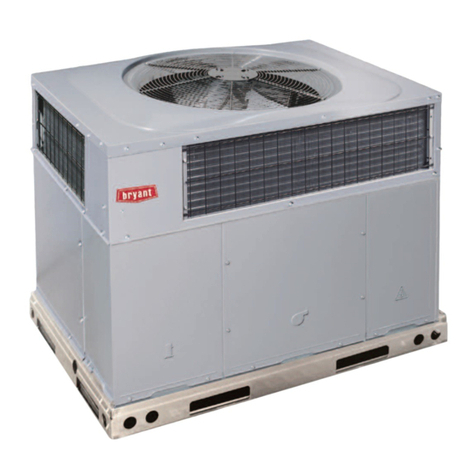
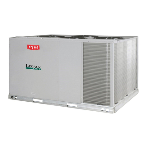
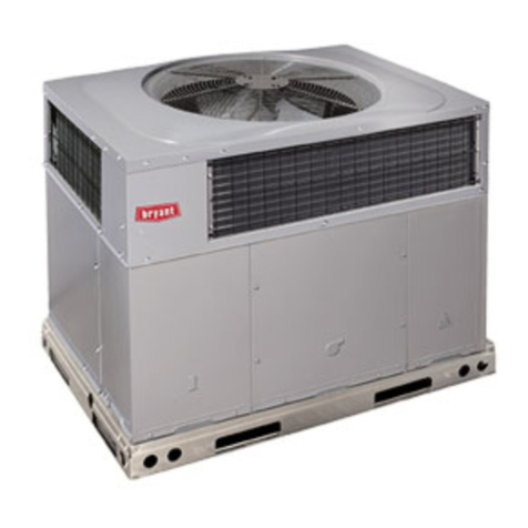
Legacy™ Line
558J 08-16
Single Package Rooftop Cooling Only
with Puron®(R-410A) Refrigerant
