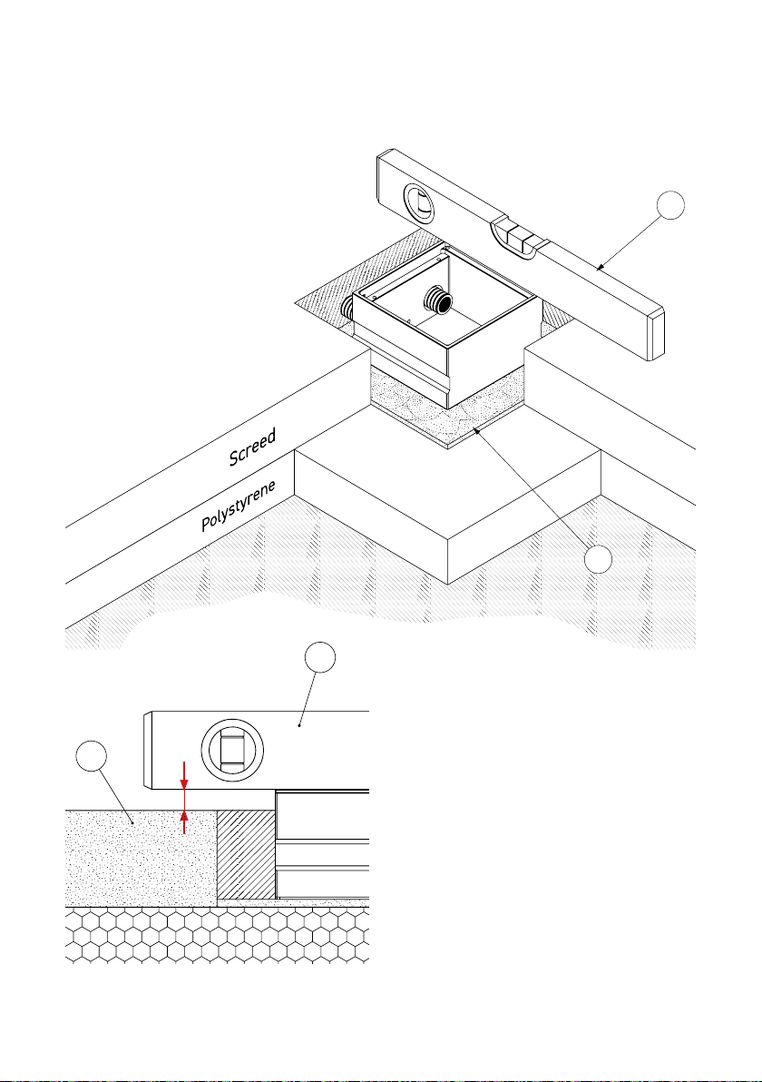
BS 88 A Series User manual

Bedienungsanleitung
Instruction Manual
88er A/E-Serie
88 A/E-Series

2
Inhalt/Contents
Produktbeschreibung ���������������������������� 3
Technische Daten������������������������������������ 4
Montageanleitung����������������������������������� 5
Gebrauchshinweise�������������������������������13
Product description ������������������������������������ 3
Technical data����������������������������������������������� 4
Assembly instructions ������������������������������� 8
Instructions for use ���������������������������������� 13

3
1
3
4
2
88er A-Serie/88 A-Series
Exemplarisch ist die Bodensteckdose 8802A
abgebildet. Das Montageprinzip gilt für
alle Bodensteckdosen der 88er A-Serie: 8802A,
8808A und der 88er E-Serie: 8802E, 8804E,
8808E.
The 8802A floor socket is shown as an
example� The installation principle applies
to all floor sockets from the 88 A-Series:
8802A, 8808A and to the 88 E-Series: 8802E,
8804E, 8808E�
Bezeichnung/Designation:
Deckel/Lid
Geräteträger/Device carrier
Steckdose/Socket
Gehäuse/Box

4
Technische Daten/Technical specifications
Art.-Nr.
Item No 8802A 8802E 8804E
Einbaumaße
Instl dim 125x125x72 mm 125 x125 x 72 mm 220 x150 x 72mm
Zuleitungen
Supply line
2x hinten/back
Ø 25mm
2x hinten/back
Ø 25mm
4x hinten/back
Ø 25mm
Nivellierbar
Height adj 5mm 5mm 5mm
Schutzart
Protection IP20 IP20 IP20
Belastbarkeit
Load
Flächenlast/Area load
max� 300kg
Flächenlast/Area load
max� 400kg
Flächenlast/Area load
max� 400kg
Art.-Nr.
Item No 8808A 8808E
Einbaumaße
Instl dim 240x240x 62 mm 240 x 240 x 62 mm
Zuleitungen
Supply line
8x seitlich/lateral
Ø 25mm
8x seitlich/lateral
Ø 25mm
Nivellierbar
Height adj 5mm 5mm
Schutzart
Protection IP20 IP20
Belastbarkeit
Load
Flächenlast/Area load
max� 400kg
Flächenlast/Area load
max� 400kg

5
Montageanleitung
P
PB
L
Schritt 1 (Vorbereitungen)
Den Deckel abnehmen (siehe links,
Umschlagseite 3)� Anschließend den
Geräteträger von dem Gehäuse
abmontieren�
Schritt 2
Vor dem Gießen des Estrichs einen
Polystyrol-Block(PB), der in seiner äußeren
Abmessung umlaufend ca� 40mm größer
ist als die Dose*, als Platzhalter auf die
ausgelegte Dämmschicht (P) kleben� Danach
die Leerrohre (L) verlegen und senkrecht
am Polystyrol-Block (PB) befestigen (zum
Beispiel mit Klebeband)�
40 mm 40 mm
40 mm
40 mm
Bodensteckdose
Ansicht von oben
PB

6
W
M
Schritt 3
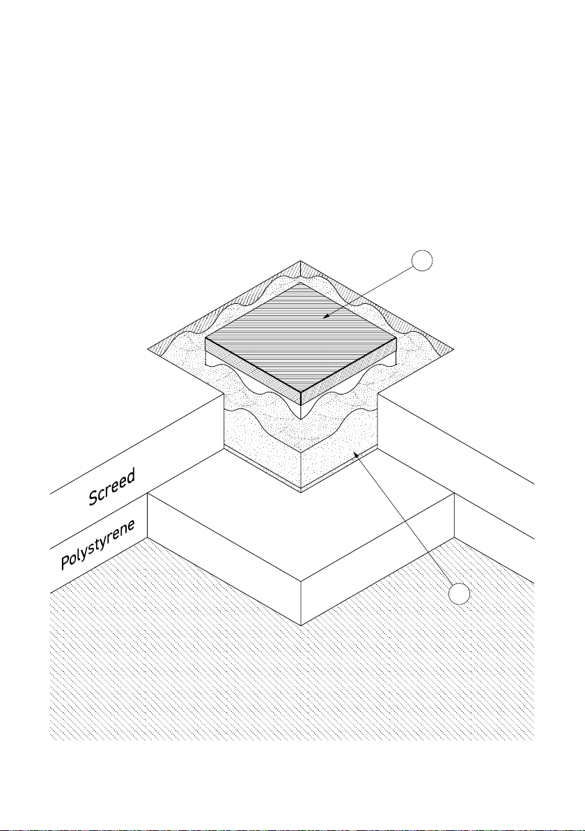
Nach dem Gießen des Estrichs den
Polystyrol-Block aus dem Estrich
entfernen� Das Gehäuse nun in
die enstandene Bodenaussparung
auf ein Mörtelbett*(M) einsetzen
und die Leerrohre in die Öffnungen
des Gehäuseseinführen�
*Achtung!
Die Höhe des Mörtelbetts muss so
vermessen werden, dass der Abstand ’t’
zwischen Wasserwaage (W) und
Estrich (E) so groß ist, wie die spätere
Belagsstärke� Zudem muss das Mörtelbett
für die entsprechende Belastung der
Bodensteckdose ausgelegt sein� Wichtig:
Zum Messen den Deckel
wieder einsetzen!
W
E
P
M
t

7
M
PD
Schritt 4
Das Gehäuseabdichten� (Tipp:
die Gehäuseöffnung beispielsweise
mit einem Pappdeckel (PD) abdecken,
wie abgebildet)� Die Aussparung
um das Gehäusenun mit Mörtel (M)
auffüllen� Die Position des Gehäuses
vor dem Aushärten des Mörtels
überprüfen!

8
Assembly Instructions
Step 1 (Preparations)
Remove the lid � Then remove the device
carrier from the box � (Page U3)�
Step 2
Before pouring the screed, a polystyrene
block (PB) with a circumference of approx�
40 mm larger than the box in its outer
dimension*must be glued to the insulation
layer (P) as a placeholder� Then lay the
conduits (L) and fix them (e�g� with adhesive
tape) vertically to the polystyrene block (PB)�
P
PB
L
40 mm40 mm
Floor socket
40 mm
40 mm
View from above
PB

9
W
M
*Attention!
The height of the mortar bed must be
measured so that the distance ’t’ between
the spirit level (W) and the screed (E) is
as large as the subsequent covering thick-
ness� In addition, the mortar bed must
be designed for the corresponding load
on the floor socket� Important: Insert the
lid
again to measure!
W
E
P
M
t
Step 3
Remove the polystyrene block (PB)
after pouring the screed� Now insert the
boxinto the resulting floor recess on
a mortar bed*(M) and install the conduits
into the openings of the box�

10
M
PD
Step 4
Seal the box� (Tip: Cover the box opening,
for example, with cardboard (PD), as shown.)
Now fill the recess around the boxwith
mortar (M)� Check the position of the box
before curing the mortar!

11
E
P
M
B
Step 5
After curing, connect the sockets, screw
the device carrierback into the box
and insert the lid � Lay the remaining
covering (B) in the room� The floor socket
is now successfully installed� (See cross
section below.)

12
Schritt 5
Nach dem Aushärten die Steckdosen
anschließen, den Geräteträger
wieder
in das Gehäuse
einschrauben und
den Deckel
einsetzen� Den restlichen
Belag (B) im Raum verlegen� Die Boden-
steckdose ist nun erfolgreich eingebaut�
(Siehe Querschnitt unten.)
E
P
M
B

13
Um eine anhaltende Funktion der Bodensteckdose
zu gewährleisten sind folgende Hinweise zu
beachten:
• Anschluss, Reparatur oder Instandhaltung sind
von einer ausgebildeten Fachkraft durchzuführen�
Während des Einbaus und der Inbetriebnahme sind
Handschuhe zu tragen�
• Für die Montage der Bodensteckdose muss
ein fester Untergrund (z�B� Estrich, Beton, etc�)
vorhanden sein�
• Bei der Montage auf einem unbefestigten
Untergrund ist die Bodensteckdose nicht begehbar�
• Die Anschlussleitung muss einen Querschnitt
entsprechend der Vorschrift des VDE aufweisen�
• Falls Kabelverschraubungen verwendet werden,
sollte diese für den entsprechenden Kabel-
querschnitt geeignet sein und eine entsprechende
Schutzart aufweisen�
• Bei Verwendung der Nivellierschrauben zur Höhen-
korrektur des Deckels ist die Bodensteckdose nur
begehbar�
• Pflegehinweis: Das Produkt ist für die Trocken-
pflege geeignet (es werden flüssigkeitslose oder
flüssigkeitsarme (nebelfeuchte) Verfahren zur
Reinigung verwendet)� Zudem dürfen für die
Reinigung keine säurehaltigen, chloridhaltigen oder
alkalische Mittel verwendet werden�
• Trotz Qualitätsprüfung kann es im Fertigungs-
prozess zu scharfen Kanten oder Ecken an Gehäuse,
Deckel oder anderen Bauteilen kommen�
• Bei mechanischen Schäden oder anderen Mängeln
(technisch/elektrisch) darf das Produkt nicht in
Betrieb genommen werden�
• Das Produkt ist unter Beachtung der nationalen
Vorschriften zu entsorgen�
Irrtümer und technische Änderungen
vorbehalten.
In order to ensure a lasting function of the
floor socket, the following instructions must
be observed:
• Connection, repair or maintenance must be carried
out by a trained specialist� During installation and
commissioning gloves must be worn�
• For the installation of the floor socket, a solid
surface (for example screed, concrete) must be
present�
• When installing on an unpaved surface, the floor
socket is not walkable�
• The connecting cable must have a cross-section
in accordance with the VDE regulation�
• If cable glands are used, they should be suitable for
the corresponding cable cross-section and have an
appropriate degree of protection�
• When using the leveling screws for height correcting
the lid, the floor socket is only accessible�
• Care instructions: The product is suitable for dry
care (liquid-free or low-liquid (mist-moist) cleaning
methods are used)� In addition, no acid-, chloride-
containing or alkaline products may be used for
cleaning�
• Despite quality inspection, sharp edges or corners
on housings, lids, or other components may occur
during the manufacturing process�
• In the case of mechanical damage or other defects
(technical/electrical), it is not allowed to put the
product into operation�
• The product is in compliance with the national
regulations to dispose�
Errors and technical changes reserved.
Gebrauchshinweise/Instructions for use

© by BS Bodensteckdosen Systemtechnik GmbH
BS Bodensteckdosen
Systemtechnik GmbH
Dingerdisser Str� 36
33699 Bielefeld, Germany
Tel +49 521 9892780
Fax+49 521 989278-30
info@bodensteckdosen�com
www�bodensteckdosen�com
Irrtümer und technische Änderungen vorbehalten.
Subject to errors and technical changes.
This manual suits for next models
6
Table of contents
Languages:
Other BS Accessories manuals