BT Versatility Packages, Spares and Maintenance items
BT Code
BT Versatility Pro. Plus (Includes System, VM, 1M,2V8)
BT Versatility Pro Plus 2+8 Digital VDS 007193
BT Versatility Pro Plus 4+16 Digital VDS 007194
BT Versatility Pro Plus 6+24 Digital VDS 007195
BT Versatility Pro Plus 8+32 Digital VDS 007196
BT Versatility Pro (Includes System,VM,4V8 and V16 with the 8/32 system) N/A
BT Versatility Pro 2+8 Digital VDS 007197
BT Versatility Pro 4+16 Digital VDS 007198
BT Versatility Pro 6+24 Digital VDS 007199
BT Versatility Pro 8+32 Digital VDS 007200
BT Versatility (Includes System, 2V8) N/A
BT Versatility 2+8 + 2V8 Digital VDS 007201
BT Versatility 4+16 +2V8 Digital VDS 007202
BT Versatility 6+24 + 2V8 Digital VDS 007203
BT Versatility 8+32 + 2V8 Digital VDS 007204
BT Versatility (System, VM,4V8 and V16 with the 8/32 system) N/A
BT Versatility 2_8+VM+4V8 Analogue VDS 007205
BT Versatility 4+16+VM+4V8 Analogue VDS 007206
BT Versatility 6+24 +VM+4V8 Analogue VDS 007207
BT Versatility 8+32+VM+4V8+V16 Analogue VDS 007208
BT Versatility (Inculdes System, 2V8) N/A
BT Versatility 2+8 +2V8 Analogue VDS 007209
BT Versatility 4+16 +2V8 Analogue VDS 007210
BT Versatility 6+24 + 2V8 Analogue VDS 007211
BT Versatility 8+32 + 2V8 Analogue VDS 007212
BT Versatility Value Add Packs N/A
BT Versatility VM & 4xV8 Phone Pack VDS 007213
BT Versatility Phone Pack 1 - 2 x V8 VDS 007214
BT Versatility Phone Pack 2 - 4 x V8 VDS 007215
BT Versatility Phone Pack 3 - 2 x V16 VDS 007216
BT Versatility Phone Pack 4 - 6 x V VDS 007217
BT Versatility Phone Pack 5 - V16 & V16 Console VDS 007218
Additional items N/A
BT Versatility Digital Line Module ISDN VDS 007219
BT Versatility Analogue Line Module VDS 007220
BT Versatility Voicemail 2P VDS 007221
BT Versatility Voicemail 4P VDS 007222
BT Versatility Internet Module VDS 007223
BT Versatility BBU VDS 007224
BT Versatility 8 Port Extension Module VDS 007225
BT Versatility Hospitality Application VDS 007226
BT Versatility Options Module VDS 007227
BT Versatility V Telephone VDS 007228
BT Versatility V8 Featurephone 007229
BT Versatility V16 Featurehone VDS 007230
BT Versatility V16 XP Expansion Console VDS 007231
BT Versatility Door Intercom VDS 007232
BT Versatility Expansion Backplane VDS 007233
BT Versatility
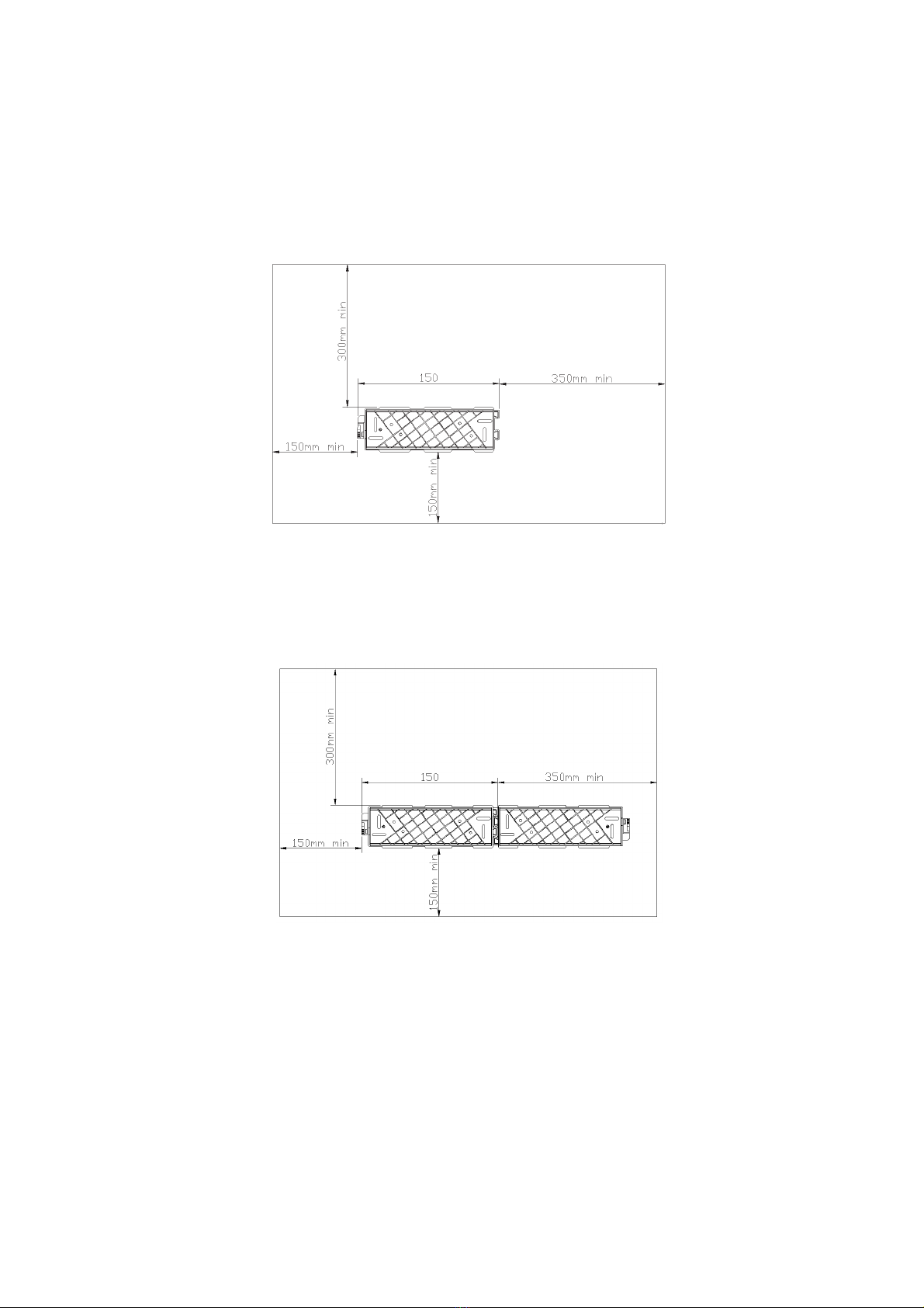
Installation and Maintenance Manual
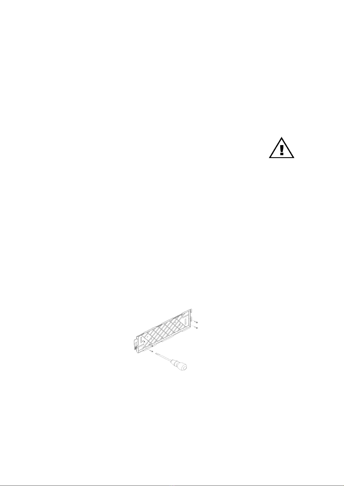
Safety Precautions during installation and system upgrades
4