manuals.online logo
Brands
  1. Home
  2. •
  3. Brands
  4. •
  5. Bticino
  6. •
  7. Intercom System
  8. •
  9. Bticino 308040 User manual

Bticino 308040 User manual

308040
04/20-01 PC
LE12096AA
BTicino SpA – Viale Borri, 231 – 21100 Varese – Italy – www.bticino.com
• Dimensional data
• Données dimensionnelles
• Abmessungsdaten
160 – 165 cm
135 – 140 cm
180 mm
330 mm
130 mm
262 mm
50 mm
58 mm
54 mm
58 mm
308026
• Wall mounted installation
• Installation murale
• Aufputz Installation
• The camera must not be installed facing strong light sources, or in locations where the area being shot is strongly backlit. In order to resolve these problems, we recommend that the
camera is installed at a height of 180 cm, instead of the usual 160 – 165 cm, with the lens pointing down. This will improve image quality. In low light situations, the colour rendition
of the image displayed by the colour camera may decrease.This is to ensure that the person being displayed can be better recognised. To ensure optimum vision in low lit rooms, the
installation of an additional light source is recommended.
• La caméra ne doit pas être installée face à des sources lumineuses intenses ni à un endroit où la personne faisant face à la caméra serait en contrejour. Pour résoudre les problèmes précédemment
décrits, il est recommandé de modifier la hauteur d’installation de la caméra, généralement à 160 – 165 cm, et de la placer à une hauteur de 180 cm et d’orienter l’objectif vers le bas de façon à
améliorer la qualité des images.
En conditions de faible luminosité, l’image visualisée des caméras couleur peut causer une diminution du rendu chromatique au bénéfice d’une meilleure reconnaissance de la personne cadrée.
Pour une vision optimale, il est recommandé dans tous les cas, dans les environnements peu éclairés, de prévoir une source d’éclairage supplémentaire.
• Die Kamera darf nicht gegenüber starken Lichtquellen oder an Orten installiert werden, an denen der aufgenommene Bereich stark von hinten beleuchtet wird. Um diese Probleme zu
lösen, empfehlen wir, die Kamera in einer Höhe von 180 cm statt der üblichen 160 - 165 cm mit nach unten gerichtetem Objektiv zu installieren. Dadurch wird die Bildqualität verbessert.
Bei schlechten Lichtverhältnissen kann die Farbwiedergabe des von der Farbkamera angezeigten Bildes abnehmen. Dies soll sicherstellen, dass die angezeigte Person besser erkannt
werden kann. Um eine optimale Sicht in schwach beleuchteten Räumen zu gewährleisten, wird die Installation einer zusätzlichen Lichtquelle empfohlen.
• Flush mounted installation
• Installation encastrée
• Unterputz Installation
23
4
1
179 mm
329 mm
2
• Wall mounted installation
• Installation murale
• Unterputz Installation
23
1
308026
• Installing the accessories
• Installation accessoires
• Installation des Zubehörs
• VIGIK® transponder reader
• Lecteur transpondeur T25 - VIGIK®
• VIGIK® Transponder-Lesegerät
• CCT75NM key switch
• Interrupteur à clé CCT75NM
• CCT75NM Schlüsselschalter
2
2
2
2
1
1
1
1
3
12
3
5
6
• Camera lens and display glass replacement
• Changement de la lentille de la caméra et du verre de l’écran
• Ersatz für Kameralinse und Displayglas
• To protect from acts vandalism, for the most delicate parts of the device we have included item 308034. This item makes it possible to replace the camera lens and the display
glass in one operation.
• En cas d’actes de vandalisme, a été prévu l’article réf. 308034 pour la partie la plus délicate du dispositif. Cet article permet de changer en une seule opération la lentille de la caméra et le
verre de l’écran.
• Zum Schutz vor Vandalismus haben wir für die empfindlichsten Teile des Gerätes den Artikel 308034 aufgenommen. Dieser Artikel ermöglicht es, das Kameraobjektiv und das
Displayglas in einem Arbeitsgang auszutauschen.
4
308034
• Completing the installation
• Terminer l’installation
• Fertigstellung der Installation
• Warning: before securing the entrance panel to the wall fit the protection caps in their housings,
ensuring that they are positioned correctly
• Attention : avant de fixer le poste externe à la paroi, replacer les bouchons de protection dans leur
logement en veillant à les positionner correctement.
• Achtung: Bevor Sie die Aussensprechstelle an der Wand befestigen, bringen Sie die Schutzkappen in
ihren Gehäusen an und stellen Sie sicher, dass sie richtig positioniert sind.
4
• Description
• Description
• Beschreibung
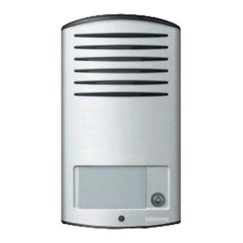
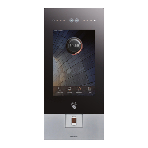
1. Loudspeaker
2. Green LED: door open notification
3. Microphone
4. Display
5. Key used to send the call to the selected resident, or to the switchboard
6. Door lock release key
7. Preset for VIGIK® reader, or key lock release
8. Delete key
9. Alphanumeric keypad
10. Resident search keys
11. Green LED: call forwarded
Red LED: system busy
12. Green LED: communication active
13. 4 x lighting LED
14. Camera
15. Loudspeaker volume adjustment
16. Jumpers (see table in the Programming section).
17. SCS/BUS connection
18. Connection of the door lock and door lock release pushbutton
19. Additional power supply
20. Configurator socket
21. MiniUSB connector for the connection to the PC
22. Microphone volume adjustment
1. Haut-parleur
2. Voyant vert: indication porte ouverte
3. Micro
4. Écran
5. Touche d’appel du résident sélectionné ou du standard de concierge
6. Touche d’ouverture serrure
7. Prédisposition pour lecteur VIGIK® ou ouverture à clé
8. Touche d’effacement
9. Clavier alphanumérique
10. Touche de recherche résident
11. Voyant vert: appel transmis
Voyant rouge : système occupé
12. Voyant vert: communication active
13. 4 voyants lumineux
14. Caméra
15. Réglage volume haut-parleur
16. Cavalier (voir tableau au chapitre Programmation)
17. Branchement BUS SCS
18. Branchement serrure et bouton d’ouverture porte locale
19. Alimentation supplémentaire
20. Logement configurateurs
21. Connecteur MiniUSB pour configuration avec PC
22. Réglage volume micro
1. Lautsprecher
2. LED zur Statusanzeige (grün = Tür offen)
3. Mikrofon
4. LCD-Graphik-Display
5. Taste zur Weiterleitung des Anrufs an den ausgewählten Teilnehmer
6. Türöffner-Freigabetaste
7. Vorbereitung für die Installation eines T25 Vigik-Transponder-Leser oder eines
Schlüsselschalters
8. Löschtaste
9. Alphanumerische Tastatur
10. AUF-AB Adressbuch-Scrolltasten
11. Grün LED: Anruf weitergeleitet Rot LED: System besetzt
12. Grün LED: Kommunikation aktiv
13. 4 x LED Beleuchtung (Kamera)
14. Weitwinkel-Farbkamera mit integriertem Lautsprechermodul
15. Lautstärker Regelung des Lautsprechers
16. Jumper (siehe Tabelle im Abschnitt Programmierung)
17. SCS/BUS-Anschluss
18. Anschluss des Türschlosses und Türöffner-Taste
19. Zusätzliche Stromversorgung
20. Konfiguratoren-Steckplatz
21. Mini-USB-Stecker für den Anschluss an den PC
22. Mikrofon-Lautstärkeregelung
1
2
3
4
9
12
10
11
5
68
14
13
7
15
19
22
18
20
21
17
16
5
• Phisical conguration
• Conguration phisique
• Physische Kongurationa
• Technical features
• Caractéristiques techniques
• Technische Daten
• 1/4”sensor
• lens F: 2,1 mm; f: 1,0 mm
• Power supply 18 – 27 Vdc
• Absorption:
105 mA (stand-by)
340 mA (max in operation)
• Interlaced 2:1
• 400 lines resolution(horizontal centered)
• Night lighting by the white LEDs
• Automatic brightness adjustment
• Operating temperature (-25) – (+70) °C
• Angle of vision:
horizontal 124°
vertical 100°
• Protection index: IP54
• Protection index against mechanical impact: IK07
• Capteur de 1/4”
• Objectif F: 2,0 mm ; f: 1,0 mm
• Alimentation: 18 – 27 Vdc
• Absorption:
105 mA (en stand by)
340 mA (max. en fonctionnement)
• Entrelacement: 2:1
• Résolution: 400 lignes (horizontales, au centre)
• Éclairage nocturne avec LEDs blancs
• Réglage automatique luminosité
• Température de fonctionnement: (-25) – (+70) °C
• Angle de cadrage:
horizontal 124°
vertical 100°
• Degré de protection: IP54
• Degré de robustesse: IK07
• 1/4”Sensor
• Linse F: 2,1 mm; f: 1,0 mm
• Stromversorgung 18 – 27 Vdc
• Verbrauch:
105 mA (Standby)
340 mA (max im Betrieb)
• Interlaced 2:1
• 400 Linien Auflösung (horizontal zentriert)
• Nachtbeleuchtung durch die weißen LEDs
• Automatische Helligkeitsanpassung
• Betriebstemperatur (-25) – (+70) °C
• Blickwinkel:
horizontal 124°
vertikal 100°
• Schutzindex: IP54
• Schutzindex gegen mechanische Wirkung: IK07
J1 J2 J3
P= Entrance panel number; Numéro du poste externe;
Adresse der Türstation
N= Call number (Not used); Numéro d’appel (pas utilisé);
Rufnummer (Nicht verwendet)
T= Door lock time delay; Temporisation serrure;
Zeitverzögerung für Türschloss
S= Type of call signal; Type de signal d’appel;
Signaltyp des Tür Rufes
J1 - Jumper connected to J1 (default) = control speech synthesis enabled; sound
notification disabled.
Cavalier sur J1 (par défaut) = synthèse vocale activée ; signal à tonalités désactivé.
Jumper gesteckt mit J1 (Standard) = Steuerung der Sprachsynthese aktiviert;
Tonbenachrichtigung deaktiviert.
J2 - Jumper connected to J2 = control speech synthesis disabled; sound notification enabled
Cavalier sur J2 = synthèse vocale désactivée ; signal à tonalités activé
Jumper gesteckt mit J2 = Steuerung der Sprachsynthese deaktiviert;
Tonbenachrichtigung aktiviert
J3 - Remove in case of additional power supply; Extraire en cas d’alimentation supplémentaire
Bei zusätzlicher Spannungsversorgung entfernen
Warnings and consumer rights
Read carefully before use and keep for future reference
Touching the units with wet hands is forbidden
Using liquid cleaners or aerosols is forbidden
Blocking the ventilation openings is forbidden
Modifying the devices is forbidden
Removing protective parts from the devices is forbidden
Installing the units near liquids and powders is forbidden
Installing the units near heat sources is forbidden
Installing the units near harmful gases, metal dusts or similar is forbidden
Fastening the units on unsuitable surfaces is forbidden
Risk of devices falling because the surface on which they are installed collapses or inappropriate installation
Switch the power supply OFF before any work on the system
Caution: Installation, conguration, starting-up and maintenance must be performed exclusively by
qualied personnel.
Check that the wall installation has been carried out correctly
Lay out the wires respecting the standards in force
Connect the power supply wires as indicated
Use only the items indicated in the technical specications for any system expansions
Avertissements et droits du consommateur
Lire attentivement avant toute utilisation et installation de nos produits et conserver pour toute consul-
tation en cas de besoin.
Interdiction de toucher les unités avec les mains mouillées.
Interdiction d’utiliser des produits de nettoyage liquides ou des aérosols.
Interdiction de boucher les ouvertures de ventilation.
Interdiction de modier les dispositifs.
Interdiction des retirer les parties de protection des dispositifs.
Interdiction d’installer les unités à proximité de liquides et poudres/poussières.
Interdiction d’installer les unités à proximité de sources de chaleur.
Interdiction d’installer les unités à proximité de gaz nocifs, de poudres métalliques ou autres matières semblables.
Interdiction de xer les unités sur des surfaces non appropriées.
Risque de chute des dispositifs en cas derupture de la surface sur laquelle ils sont installés ou mauvaise installation.
Couper l’alimentation avant toute intervention sur l’installation.
Attention: les opérations d’installation, de conguration, de mise en service et d’entretien doivent être
conées à un personnel qualié.
S’assurer que l’installation murale est correctement eectuée.
Eectuer la pose des câbles dans le respect des normes en vigueur.
Brancher les câbles d’alimentation dans le respect des indications fournies.
Pour les éventuelles extensions de l’installation, utiliser uniquement les articles indiqués dans les carac-
téristiques techniques.
• Hinweise und Rechte der Verbraucher
Vor Gebrauch, die Hinweise aufmerksam durchlesen und sorgfältig aufbewahren, um sie auch in Zukunft nachschlagen zu können.
Verbot, die Einheiten mit nassen Händen zu berühren
Verbot, Flüssigreiniger oder Aerosol zu benutzen
Verbot, die Belüftungsschlitze abzudecken
Verbot, die Vorrichtungen zu ändern
Verbot, die Schutzbleche von den Vorrichtungen abzunehmen
Verbot, die Einheit in der Nähe von Flüssigkeiten und Staub zu installieren
Verbot, die Einheit in der Nähe vonWärmequellen zu installieren
Verbot, die Einheit in der Nähe von giftigem Gas, Metallstaub o. ä. zu installieren
Verbot, die Einheit an ungeeignete Flächen zu befestigen
Risiko des Herabfallens derVorrichtungen durch Nachlassen der Auageäche oder wegen falscher Installation
Die Stromversorgung abtrennen, bevor an der Anlage gearbeitet wird.
Achtung: die Installation, Konguration, Inbetriebnahme und Wartung dürfen nur von qualizierten Fachleuten vorgenommen werden.
Sicherstellen, dass die Wandmontage richtig vorgenommen wird
Die Kabeln gemäß geltenden Normen verlegen
Die Stromkabeln gemäß Anweisungen anschließen
Bei eventuellen Anlagenerweiterungen ausschließlich die Artikel verwenden, die in den technischen Spezikationen angegeben sind
Other manuals for 308040

1

This manual suits for next models

1

Other Bticino Intercom System manuals

Bticino 368921 User manual

Bticino

Bticino 368921 User manual

Bticino 363910 User manual

Bticino

Bticino 363910 User manual

Bticino 317011 User manual

Bticino

Bticino 317011 User manual

Bticino 308040 User guide

Bticino

Bticino 308040 User guide

Bticino 343081 User manual

Bticino

Bticino 343081 User manual

Bticino 374004 User manual

Bticino

Bticino 374004 User manual

Bticino 322040 User manual

Bticino

Bticino 322040 User manual

Bticino 344643 User manual

Bticino

Bticino 344643 User manual

Bticino 365511 User manual

Bticino

Bticino 365511 User manual

Bticino CLASSE 100X16E User manual

Bticino

Bticino CLASSE 100X16E User manual

Bticino AXOLUTE Nighter User manual

Bticino

Bticino AXOLUTE Nighter User manual

Bticino Sfera video kit User guide

Bticino

Bticino Sfera video kit User guide

Bticino 366811 User manual

Bticino

Bticino 366811 User manual

Bticino 346310 User manual

Bticino

Bticino 346310 User manual

Bticino Small Entrance Panel Compact Operating manual

Bticino

Bticino Small Entrance Panel Compact Operating manual

Bticino 366611 User manual

Bticino

Bticino 366611 User manual

Bticino 364614 User manual

Bticino

Bticino 364614 User manual

Bticino 315111 Operating manual

Bticino

Bticino 315111 Operating manual

Bticino 317013 User manual

Bticino

Bticino 317013 User manual

Bticino Terraneo 332550 User manual

Bticino

Bticino Terraneo 332550 User manual

Bticino 369911 User manual

Bticino

Bticino 369911 User manual

Bticino 375006 User manual

Bticino

Bticino 375006 User manual

Bticino 322011 User manual

Bticino

Bticino 322011 User manual

Bticino 344163 Polyx Memory Display User manual

Bticino

Bticino 344163 Polyx Memory Display User manual

Popular Intercom System manuals by other brands

Fermax CITY 4+N OUTDOOR PANEL Installer manual

Fermax

Fermax CITY 4+N OUTDOOR PANEL Installer manual

Steren CCTV-040 instruction manual

Steren

Steren CCTV-040 instruction manual

Hollyland 0108B manual

Hollyland

Hollyland 0108B manual

ELEKTROBOCK BZ30 manual

ELEKTROBOCK

ELEKTROBOCK BZ30 manual

Bpt Futura X2 manual

Bpt

Bpt Futura X2 manual

Optimus MP-C1 quick guide

Optimus

Optimus MP-C1 quick guide

Vimar Elvox 6A40 instruction sheet

Vimar

Vimar Elvox 6A40 instruction sheet

GVS H Series user manual

GVS

GVS H Series user manual

SSS Siedle A 150-10 Product information

SSS Siedle

SSS Siedle A 150-10 Product information

golmar Vista Nexa instruction manual

golmar

golmar Vista Nexa instruction manual

RTS BTR-800 operating instructions

RTS

RTS BTR-800 operating instructions

SSS Siedle SET CAB 850-1 Product information

SSS Siedle

SSS Siedle SET CAB 850-1 Product information

Comelit UT1020VC Programming manual

Comelit

Comelit UT1020VC Programming manual

RTS TIF-4000 Frame user manual

RTS

RTS TIF-4000 Frame user manual

SSS Siedle BTSV 850 Series System manual

SSS Siedle

SSS Siedle BTSV 850 Series System manual

DKS 1812 Plus Installation & owner's manual

DKS

DKS 1812 Plus Installation & owner's manual

golmar Stadio Plus 4113/AL instruction manual

golmar

golmar Stadio Plus 4113/AL instruction manual

Comelit KCA2061A Technical manual

Comelit

Comelit KCA2061A Technical manual

manuals.online logo
manuals.online logoBrands
  • About & Mission
  • Contact us
  • Privacy Policy
  • Terms and Conditions

Copyright 2025 Manuals.Online. All Rights Reserved.