manuals.online logo
Brands
  1. Home
  2. •
  3. Brands
  4. •
  5. Bticino
  6. •
  7. Intercom System
  8. •
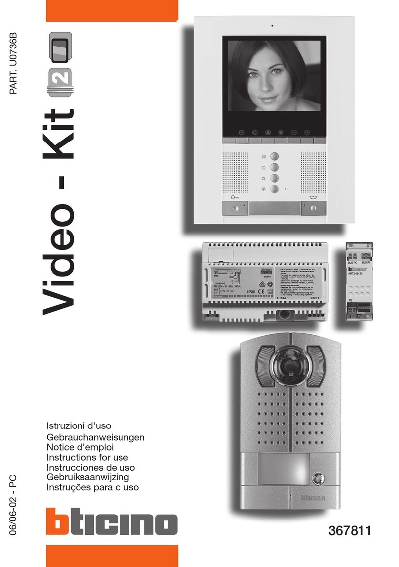
  9. Bticino Kit Video 2 User manual

Bticino Kit Video 2 User manual

06/07-01 - PC PART. U1083C
Istruzioni d’uso
Gebrauchanweisungen
Notice d’emploi
Instructions for use
Instrucciones de uso
Gebruiksaanwijzing
Instruções para o uso
Kit Video
368421
3
I
NL
F
GB
E
D
P
I
NL
F
GB
E
D
P
VECCHIO IMPIANTO A CAMPANELLO
Impianto esistente con 3 fili e due chiamate
ALTE KLINGELANLAGE
Vorhandene Anlage mit 3 Leitern und zwei Rufen
ANCIENNE INSTALLATION A SONNETTE
Installation existante à trois fils et deux appels
OLD SYSTEM WITH BELL
Existing system with 3 wires and two calls
VIEJA INSTALACIÓN CON TIMBRE
Instalación existente con 3 hilos y dos llamadas
OUDE DEURBELINSTALLATIE
Bestaande installatie met 3 draden en twee oproepen
ANTIGA INSTALAÇÃO EM CAMPAÍNHA
Instalação existente com 3 fios e duas chamadas.
NUOVO IMPIANTO VIDEOCITOFONICO A COLORI
Impianto realizzato senza modifiche ai 2 fili esistenti:
chiamata, videocitofono e serratura.
NEUE ANLAGE FÜR FARBVIDEOHAUSTELEFON
Anlage ohne Änderungen an den vorhandenen 2 Leitern:
Ruffunktion, Videohaustelefon und elektrisches Schloss.
NOUVELLE INSTALLATION VIDÉOPHONIQUE COULEURS
Installation réalisée sans modifications sur les 2 fils
existants: appel, vidéophone, et serrure électrique.
NEW COLOUR VIDEO DOOR ENTRY SYSTEM
System made without modifications to the 2 existing
wires: call, video door entry and electric door lock.
NUEVO VIDEOINTERFONO EN COLOR
Instalación realizada sin las modificaciones a los 2 hilos
existentes: llamada, vídeointerfono y cerradura eléctrica.
NIEUWE KLEUREN-VIDEOHUISTELEFOONINSTALLATIE
Installatie aangelegd zonder wijzigingen aan de 2 bestaande
aders: oproep, video-deurtelefoon en elektrisch deurslot.
NOVA INSTALAÇÃO DO INTERCOMUNICADOR VÍDEO
Instalação realizada sem modificar os 2 fios existentes:
chamada, intercomunicador vídeo e fechadura eléctrica.
4
Kit Video

35
185
106




4
5
5




�

7
8
Prima dell’installazione assicurarsi che la vite sia completamente avvitata.
Vor der Installation sicherstellen, dass die Schraube richtig festgeschraubt ist.
Avant l’installation, s’assurer que la vis soit complètement vissée.
Before installing make sure that the screw is completely tightened.
Antes de la instalación, compruebe que el tornillo esté completamente enroscado.
Vóór de installatie controleren of de schroef volledig vastgedraaid is.
Antes da instalação verificar se o parafuso está completamente atarraxado
*
Premere con forza
Fest drücken
Appuyer avec force
Press hard
Presione con fuerza.
Met kracht duwen
Carregar com força
5÷10mm
6
Kit Video
- La telecamera non deve essere installata di fronte a grandi sorgenti luminose, oppure in luoghi
dove il soggetto ripreso rimanga molto in controluce. Per risolvere i problemi precedentemente
descritti si consiglia di variare l’altezza di installazione della telecamera, solitamente 160-165 cm,
ad un’altezza di 180 cm e di orientare l’obiettivo verso il basso in modo da migliorare la qualità
delle riprese.
- Nota: Le telecamere con sensore CCD a colori presentano, in condizioni di scarsa luminosità, una
sensibilità inferiore rispetto alle telecamere in bianco/nero. Si consiglia pertanto, in ambienti poco
illuminati di prevedere una fonte di illuminazione aggiuntiva.
- Die Kamera darf nicht vor starken Lichtquellen oder an Orten installiert werden, wo das Subjekt
sich im Gegenlicht befindet. Um die zuvor erwähnten Probleme zu lösen, empfehlen wir die In-
stallationshöhe der Kamera zu ändern, d.h. sie anstatt auf 160-165 cm Höhe, auf 180 cm Höhe zu
installieren und das Objektiv nach unten zu orientieren, um die Aufnahmequalität zu verbessern.
- Bemerkung: Farbkameras mit CCD-Aufnahmeelement besitzen bei schlechter Beleuchtung eine
geringere Empfindlichkeit als Schwarz/Weiß Kameras. Wir empfehlen daher eine zusätzliche Be-
leuchtungsquelle vorzusehen.
- La télécaméra ne doit pas être installée en face de fortes sources lumineuses, ou bien dans des
endroits où le sujet pris reste très à contre-jour. Pour résoudre les problèmes précédemment
décrits, il est conseillé de porter la hauteur d’installation de la télécaméra, normalement 160-165
cm, à une hauteur de 180 cm et d’orienter l’objectif vers le bas de façon à améliorer la qualité
des prises de vue.
- Nota: les télécaméras avec capteur CCD couleurs présentent, dans des conditions de faible
luminosité, une sensibilité inférieure aux télécaméras noir/blanc. Il est donc conseillé, dans des
milieux peu éclairés, de prévoir une source de lumière supplémentaire.
- The camera must not be installed in front of large light sources, or in places where the subject
viewed remains in deep shadow. To solve the problems described above change the height at
which the camera is installed, normally 160 to 165 cm, to a height of 180 cm, and face the lens
downwards to improve the quality of the views.
- Note: in poor lighting conditions cameras with colour CCD detector are less sensitive than black/
white cameras. An extra lighting source should be added in poorly lit rooms.
- La telecámara no debe ser instalada delante de fuentes luminosas grande en lugares en donde el
individuo filmado se encuentre demasiado en contraluz. Para solucionar los problemas descritos
antes, es aconsejable modificar la altura de instalación de la telecamera, de 160-165 cm a 180
cm y enfocar el objetivo hacia abajo para optimizar la calidad de la filmación.
- Nota: las telecámaras con sensor CCD en colores presentan, en condiciones de escasa lumi-
nosidad, una sensibilidad inferior respecto a las telecámaras en blanco/negro. Por lo tanto es
aconsejable en ambientes escasamente iluminados prever una fuente de iluminación extra.
- Installeer de camera niet tegenover grote lichtbronnen of op plaatsen waar de opname van het
onderwerp door sterk tegenlicht wordt gestoord. Voorgaande problemen zijn op te lossen door
de camera op een hoogte van 180 cm te installeren (in plaats van 160-165 cm) en het objectief
omlaag te richten zodat de kwaliteit van de opnames beter zal zijn.
- Opmerking: camera’s met kleuren-CCD-sensor zijn bij een zwakke verlichting minder gevoe-
lig dan zwart-wit camera’s. Daarom is het raadzaam om zwak verlichte omgevingen van extra
verlichting te voorzien.
- A câmara não deve ser montada diante de fortes fontes de luz, ou então em lugares onde o
elemento que deve ser filmado fique muito em contraluz. Para resolver os problemas supramen-
cionados recomenda-se variar a altura da instalação da câmara, que habitualmente é de 160-165
cm, para uma altura de 180 cm e orientar a objectiva para baixo a fim de melhorar a qualidade
das filmagens.
- Nota: as câmaras com sensor CCD em cores apresentam, quando há pouca luminosidade, uma
sensibilidade inferior em relação às câmaras em branco e preto. Portanto, recomenda-se, quan-
do os ambientes forem pouco iluminados providenciar uma fonte de iluminação adicional
I
NL
F
GB
E
D
P
7
L’immagine visualizzata è ottimale per
un angolo di osservazione di 40°.
Das angezeigte Bild ist optimal für
einen Sichtwinkel von 40°.
L’image visualisée est parfaite pour un
angle d’observation de 40°.
The displayed picture is optimum for
an observation angle of 40°.
La imagen visualizada es excelente
para un ángulo de observación de 40°.
Het gevisualiseerde beeld is optimaal
voor een observatiehoek van 40°.
A imagem visualizada é óptima para
um ângulo de observação de 40°.
OK
40
10
30
I
NL
F
GB
E
D
P
1
2
30 mm
151 mm
168 mm
8
Kit Video
3
I
NL
F
GB
E
D
P
I
NL
F
GB
E
D
P
4
Per il fissaggio della base utilizzare tasselli ad espan-
sione e viti. Non fissare la base direttamente alla
scatola da incasso.
Zur Befestigung der Halterung Spreizdübeln und
Schrauben verwenden. Die Halterung nicht direkt
an die UP-Schachtel befestigen.
Pour la fixation de la base, utiliser des chevilles à
expansion et des vis. Ne pas fixer la base directe-
ment à la boîte d’encastrement.
To fasten the base use screw anchors and screws.
Do not fasten the base directly to the flush-
mounted box.
Para la fijación de la base, utilice tacos de expan-
sión y tornillos. No fije la base directamente a la
caja empotrable.
Voor de vasthechting van de basis uitzetpluggen en
schroeven gebruiken. De basis niet rechtstreeks
aan de inbouwdoos bevestigen.
Para fixar a base utilizar os parafusos de expansão
e parafusos. Não fixar a base directamente na
caixa de encaixar.
Collegare il Polyx Video Display al BUS dell’im-
pianto
Die Polyx Video Display mit dem BUS der Anlage
verbinden
Raccorder la Polyx Video Display au BUS de l’ins-
tallation.
Connect the Polyx Video Display to the system BUS
Conecte la Polyx Video Display al BUS del sistema
Het Polyx Video Display verbinden met de BUS van
de installatie
Conectar o Polyx Video Display ao BUS da instalação
9
6
A
I
NL
F
GB
E
D
P
A
I
NL
F
GB
E
D
P
5
Per estrarre il Polyx Video Display dalla base abbassa-
re la linguetta di fermo A servendosi di un cacciavite,
quindi spingere il Polyx Video Display verso l'alto.
Um die Polyx Video Display aus der Halterung zu
nehmen, die Sperrfeder A mit einem Schraubenzie-
her nach unten drücken und die Polyx Video Display
nach oben herausziehen.
Pour extraire la Polyx Video Display de la base,
abaisser la languette d’arrêt A, en se servant d’un
tournevis, puis pousser la Polyx Video Display vers
le haut.
To extract the Polyx Video Display from the base
lower the stop tab A using a screwdriver, then push
the Polyx Video Display upwards.
Para extraer la Polyx Video Display de la base, baje
la lengüeta de bloqueo A utilizando un destornil-
lador, luego empuje la Polyx Video Displays hacia
arriba.
Om het Polyx Video Display uit de basis te trekken,
het blokkeerstrookje A neerlaten gebruikmakend
van een schroevendraaier, vervolgens het Polyx Vi-
deo Display naar boven duwen.
Para extrair o Polyx Video Display da base abaixar
a lingueta de parada A utilizando uma chave de
parafuso, então empurrar o Polyx Video Display
para cima.
Dopo aver effettuato tutti i collegamenti fissare il Polyx
Video Display alla base avendo cura di disporre i fili in
modo che non vengano danneggiati.
Nachdem alle Anschlüsse vorgenommen worden
sind, die Polyx Video Display an die Halterung be-
festigen und darauf achten, dass dabei die Leiter
nicht beschädigt werden.
Après avoir effectué tous les raccordements, fixer
la Polyx Video Display à la base, en ayant soin de
disposer les fils de façon à ce qu’ils ne soient pas
endommagés.
After making all the connections fasten the Polyx
Video Display to the base, being careful to arrange
the wires so that they are not damaged.
Después de haber efectuado todas las conexiones,
fije la Polyx Video Display a la base prestando aten-
ción a disponer los hilos de manera que no sean
dañados.
Nadat men alle verbindingen heeft uitgevoerd, het
Polyx Video Display vasthechten aan de basis en
ervoor zorgen dat de draden zodanig geplaatst zijn
dat ze niet beschadigd worden.
Depois de ter realizado todos as conexões fixar o
Polyx Video Display à base tendo cuidado de colocar
os fios de maneira que não fiquem danificados.
10
Kit Video
Sede configuratori
Sitz der Konfiguratoren
Logement configurateurs
Configurator seat
Alojamento configuradores
Plaats van de configuratie modules
Alojamento configurador
I
NL
F
GB
E
D
P
7
I
NL
F
GB
E
D
P
I
NL
F
GB
E
D
P
Spostare su ON solo nell’ultimo
videocitofono che termina la tratta.
Nur am letzten Videohaustelefon
der Strecke auf ON schalten
Déplacer sur ON seulement sur le der-
nier vidéophone qui termine le tronçon
Move to ON only in the last video
handset which ends the section
Lleve a ON sólo en el último video-
portero que termina el tramo
Op ON verplaatsen alleen in de
laatste huisbeeldtelefoon die het
stuk beëindigt
Colocar em ON somente no último in-
tercomunicador que termina o trecho
Collegamento al BUS dell’impianto
Anschluss an den BUS der Anlage
Raccordement au BUS de l’installation
Connecting the BUS to the system
Conexión al BUS del sistema
Verbinding met de BUS van de installatie
Conexão ao BUS da instalação
I
NL
F
GB
E
D
P
Collegamento di un eventuale
alimentatore supplementare
Anschluss eines eventuellen zu-
sätzlichen Netzgeräts
Raccordement d’une alimentation
supplémentaire éventuelle
Connecting any extra power supply
Conexión de un eventual alimenta-
dor adicional
Verbinding van een eventuele sup-
plementaire voeder
Conexão de um eventual alimenta-
dor suplementar
11
I
NL
F
GB
E
D
P
Attenzione: il Polyx Video Display deve rispettare le seguenti regole installative:
- deve essere installato solo in ambienti interni
- non deve essere esposto a stillicidio o a spruzzi d’acqua
- non ostruire le aperture di ventilazione
- deve essere usato unicamente su sistemi 2 fili SCS Bticino.
Ogni uso improprio dell’articolo puó comprometterne le caratteristiche di sicurezza.
Achtung: die Polyx Video Display muss unter Beachtung folgender
Regeln installiert werden:
- sie darf nur im Inneren installiert werden
- sie darf nicht Wassertropfen oder -spritzer ausgesetzt werden
- Belüftungsschlitze nicht verstopfen
- Sie darf nur mit “2--Draht-Bus-System” der SCS Bticino verwendet werden.
Jeder ungeeigneter Gebrauch des Geräts kann seine Sicherheitseigenschaften
beeinträchtigen.
Attention: le Polyx Video Display doit respecter les règles d’installation suivantes:
- il doit être monté seulement à l’intérieur
- il ne doit pas être exposé à des suintements ou à des éclaboussures
- ne pas boucher les ouvertures d’aération
- il doit être utilisé uniquement sur des systèmes 2 fils SCS Bticino.
Tout usage impropre de la référence peut compromettre les caractéristiques de sécurité.
Caution: the Polyx Video Display must respect the following installation rules:
- it must only be installed indoors
- it must not be exposed to water drops or splashes
- do not block the ventilation openings
- it must be used only on SCS Bticino 2-wire systems
An improper use of the item can compromise its safety features
Atención: el Polyx Video Display debe respetar las siguientes normas de instalación:
- se debe instalar sólo al cubierto
- no debe estar expuesto a goteo o salpicones de agua
- no tape las aberturas de ventilación
- se debe utilizar exclusivamente en sistemas 2 hilos SCS Bticino.
Cualquier uso impropio del artículo puede comprometer sus características de seguridad.
Let op: Bij de installatie van de Polyx Video Display moet men de volgende voorschriften in
acht nemen:
- binnenshuis installeren
- niet aan waterdruppels en -stralen blootstellen
- de ventilatieopeningen niet versperren
- uitsluitend in 2-dradige SCS Bticino systemen installeren
Ieder oneigenlijk gebruik kan de veiligheid van het product schaden.
Atenção: o Polyx Video Display deve respeitar as seguintes regras para ser instalado:
- deve ser instalado somente internamente
- não deve ser exposto a estilicídio ou borrifos de água
- não deve obstruir as aberturas de ventilação
- deve ser usado somente em sistemas de 2 fios da SCS Bticino.
Qualquer uso impróprio do artigo pode comprometer as suas características de segurança.
12
Kit Video






 








 �


�


A = Pulsante apertura serratura
Schalter Türöffner
Poussoir d’ouverture serrure
Door lock pushbutton
Pulsador apertura cerradura
Drukknop opening
Botão para abertura da fechadura
S+S- = 18V - 4A impulsivi - 250mA mantenimento (30 Ohm max)
S+S- = 18V - 4A Impulsstrom - 250mA Haltestrom (30 Ohm max)
S+S- = 18V - 4A impulsifs - 250mA entretien (30 Ohm max)
S+S- = 18V - 4A impulsive - 250mA holding current (30 Ohm max)
S+S- = 18V - 4A impulsivos - 250mA mantenimiento (30 Ohm max)
S+S- = 18V - 4A impulsief - 250mA onderhoud (
30 Ohm
max)
S+S- = 18V - 4A instantâneos - 250mA continuos (
30 Ohm
max)
Schema base
con serratura a 2 fili
Übersichtszeichnung mit
einem 2-Draht-Schloss
Schéma de base
avec serrure à 2 fils
Basic diagram with
2 wire door lock
I
NL
F
GB
E
D
P
Esquema básico con
cerradura de 2 hilos
Basisschema met slot
met 2 draden
Esquema de base com
fechadura de 2 fios
13






 








�
 �



A = Pulsante apertura serratura
Schalter Türöffner
Poussoir d’ouverture serrure
Door lock pushbutton
Pulsador apertura cerradura
Drukknop opening
Botão para abertura da fechadura
Schema base 2
Übersichtszeichnung 2
Schéma de base 2
Basic diagram 2
Esquema básico 2
Basisschema 2
Esquema de base 2
I
NL
F
GB
E
D
P
S+S- = 18V - 4A impulsivi - 250mA mantenimento (30 Ohm max)
S+S- = 18V - 4A Impulsstrom - 250mA Haltestrom (30 Ohm max)
S+S- = 18V - 4A impulsifs - 250mA entretien (30 Ohm max)
S+S- = 18V - 4A impulsive - 250mA holding current (30 Ohm max)
S+S- = 18V - 4A impulsivos - 250mA mantenimiento (30 Ohm max)
S+S- = 18V - 4A impulsief - 250mA onderhoud (
30 Ohm
max)
S+S- = 18V - 4A instantâneos - 250mA continuos (
30 Ohm
max)
14
Kit Video



    
 


�

�



A = Pulsante apertura serratura
Schalter Türöffner
Poussoir d’ouverture serrure
Door lock pushbutton
Pulsador apertura cerradura
Drukknop opening
Botão para abertura da fechadura
Schema base
con serratura a relè
Übersichtszeichnung
mit Schloss mit Relais
Schéma base
avec serrure à relais
Basic diagram
with relay door lock
Esquema básico
con cerradura de relé
Basisschema
met slot met relais
Esquema de base
da fechadura com relè
I
NL
F
GB
E
D
P
15
Installare e collegare gli apparecchi come indicato nello schema.
Assicurarsi che durante le operazioni di montaggio degli apparecchi l’alimentatore non sia collegato alla rete pubblica.
L’a
Prima di alimentare l’impianto verificare l’esattezza del cablaggio ed accertarsi che la tensione di rete sia compatibile con quella
dell’alimentatore.
Posare i cavi seguendo lo schema riportato nelle pagine precedenti in cui è indicato il numero dei cavi da predisporre e la dislo-
cazione fisica degli apparecchi che compongono l’impianto.
Die Geräte laut Plan montieren und anschließen.
Bei der Montage der Geräte darf das Netzgerät nicht am Niederspannungsnetz angeschlossen sein.
Das Speisegerät darf nicht Tropfwasser oder Wasserspritzer ausgesetzt werden.
Belüftungsschlitze des Speisegeräts nicht verstopfen.
Bevor die Anlage mit Strom versorgt wird, sollte kontrolliert werden, ob die Verkabelung richtig vorgenommen wurde.
Prüfen Sie bitte die Anschlusswerte des Netzgerätes mit der Netzspannung.
Bitte beachten Sie die Nummerierung der Drahte auf beigefugtem Schaltplan.
In der Tabelle der nachfolgenden Seite ist der Mindestschnitt der Kabel je nach Abstand zwischen Tür- und Hausstation angegeben.
Monter et brancher les appareils comme indiqué sur le schéma.
S’assurer que pendant les opérations d’installation des appareils l’alimentation n’est pas raccordée au réseau public.
L’alimentation ne doit etre exposée ni à stillation ou à pulvérisations d’eau. Ne pas boucher les ouvertures d’aération de l’alimentation.
Avant d’alimenter l’installation, vérifier que le cablage est correct et s’assurer que la tension du réseau est compatible avec celle
de l’alimentation.
Poser les câbles d’après le schéma qui se trouve dans les pages précédentes, sur lequel est indiqué le nombre de cables à placer
et la localisation physique des appareils qui forment l’installation.
Le tableau de la page suivante indique la section minimale des câbles en fonction de la distance entre poste extérieur et poste
interne.
Install and connect the devices as indicated in the diagram.
Make sure that when the devices are mounted the power supply is not connected to the public electric power line.
The power supply must not be exposed to dripping water or splashes. Do not block the power supply ventilation openings.
Before energizing the installation chech that cabling is correct and make sure that line voltage is compatible with power supply
voltage
Lay cables according to diagram shown in the previous pages, which indicates the number of cables to be arranged and the layout
of devices that make up the installation.
The table on the following page indicates the minimum section of the wires as a function of the distance between entrance panel
and audio handset.
Instalar y conectar los aparatos como se indica en el esquema. Asegurarse de que durante las operaciones de montaje de los
aparatos, el alimentador no está conectado a la red pública.
El alimentador no debe estar expuesto a goteo o salpicones de agua. No tape las aberturas de ventilación del alimentador.
Antes de alimentar la instalación, comprobar que el cableado es correcto y asegurarse de que la tensión de red es compatible
con la del alimentador.
Colocar los cables siguiendo el esquema que se da en las páginas anteriores en las que se ha indicado el número de los cables
que hay que predisponer y la colocación fisica de los aparatos que componen la instalación.
La tabla en la página siguiente indica la sección mínima de los cables en función de la distancia entre la unidad exterior y la
unidad interior.
Installeer en verbind de apparatuur zoals aangegeven in het schema.
Controleer voordat u de installatie aansluit op het lichtnet of de bekabeling goed is aangelegd en of de netspanning geschikt is
voor de voeding.
De voeding mag niet worden blootgesteld aan waterdruppels of-stralen. Niet de ventilatieopeningen van de voeding versperren.
Vergewis u ervan dat de voeding niet op het lichtnet is aangesloten tijdens de installatie.
Leg de kabels aan volgens het schema op de volgende bladzijden waarin het nummer van de kabels en de plaatsing van de
apparaten is aangegeven.
De tabel van de volgende pagina geeft de minimum doorsnede van de kabels in functie van de afstand tussen binnenplaats en
buitenplaats.
Instalar e ligar os aparelhos conforme indicado no esquema.
Assegurar-se de que durante as operações de montagem dos aparelhos, o alimentador não está ligado à rede pública.
O alimentador
não
deve ser exposto a estililicídio ou a borrifos de água. Não obstrua as aberturas de ventilaç
ão
do alimentador.
Antes de ligar a corrente na instala
ç
ão verificar se os cabos sao correctos e certificar-se de que a tensão de rede é compativel
com a do alimentador.
Colocar os cabos seguindo o esquema das páginas anteriores onde se indica o número dos cabos a preparar e a disposi
ç
ão
fisica dos aparelhos que formam o sistema.
A tabela da página seguinte indica a secção mínima dos cabos em função da distância entre a unidade exterior e a unidade
interior.
I
NL
F
GB
P
E
D
16
Kit Video
Sezione cavi (mm2)
Kabelschnitt (mm2)
Section câbles (mm2)
Cable section (mm2)
Sección cables (mm2)
Doorsnede sleutels (mm2)
Secção cabos (mm2) 0,28
Bticino
art.336904
Bticino
art.L4669 1
30m 50m 30m 100m
>0,2mm
2
Bticino
L4669
>0,35mm
2
0,28mm
2
Bticino
C9881U/5E
AWG24 UTP5
Bticino
336904
One PTT
278 TP
0,28mm
2
One SYT
+ Digital TP
5/10
One SYT
+ 1 Num TP
5/10
GIGA_TW
CAT5E
AWG24
One SYT
+ Num TP
8/10
Cable
ARB.6060-1
6/10
Cable
EV6R
6/10
A50 140 145 200 200 145 200 50
B50 115 80 200 115 80 200 50
C50 100 65 200
100
65 200 50
>0,2mm
2
Bticino
L4669
>0,35mm
2
0,28mm
2
Bticino
C9881U/5E
AWG24 UTP5
Bticino
336904
One PTT
278 TP
0,28mm
2
One SYT
+ Digital TP
5/10
One SYT
+ 1 Num TP
5/10
GIGA_TW
CAT5E
AWG24
One SYT
+ Num TP
8/10
Cable
ARB.6060-1
6/10
Cable
EV6R
6/10
A50 100 140 200 150 140 200 50
B50 100 80 200 115 80 200 50
C50 90 60 200 90 60 200 50
Fino a 2 posti interni
Bis zu 2 Hausstationen
Jusqu’à 2 postes internes
Up to 2 handsets
Da 3 a 6 posti interni
Von 3 bis 6 Hausstationen
De 3 à 6 postes internes
From 3 to 6 handsets
Da 3 a 6 placas interiores
Van 3 tot 6 interne punten
De 3 a 6 unidades internas
Hasta 2 placas interiores
Tot 2 interne punten
Até 2 unidades internas
17
Konfiguration Türstation:
P = zur Konfiguration, siehe Pläne in diesem
Handbuch
N = zur Konfiguration, siehe Pläne in diesem Hand-
buch
T = ZEITGEBER SCHLOSSRELAIS
S = zur Konfiguration, siehe Pläne in diesem
Handbuch
Configuración placa exterior:
P = para la configuración, véanse los esquemas
presentados en este manual
N = para la configuración, véanse los esquemas
presentados en este manual
T = TEMPORIZADOR RELÉ CERRADURA
S = para la configuración, véanse los esquemas
presentados en este manual
Entrance panel configuration:
P = for the configuration see the diagrams in this
manual
N = for the configuration see the diagrams in this
manual
T = DOOR LOCK TIMER RELAY
S = for the configuration see the diagrams in this
manual
Configurazione posto esterno:
P = per la configurazione vedere gli schemi
riportati in questo manuale
N = per la configurazione vedere gli schemi
riportati in questo manuale
T = TEMPORIZZATORE SERRATURA
S = per la configurazione vedere gli schemi
riportati in questo manuale
E
GB
0= kein
Konfigurator 1 2 3 4 5 6 7
1 Sek. 2 Sek. 3 Sek.
Wie
Taste
6 Sek. 8 Sek. 10 Sek.
4 Sek.
Konfiguratornummer
ACHTUNG: Jedes Mal, wenn die Konfiguration
geändert wird, den Strom abschalten, etwa 1
Minute warten und dann wieder einschalten.
ATTENZIONE: Tutte le volte che si modifica la
configurazione è necessario togliere e ridare
l’alimentazione all’impianto, attendendo circa
1 minuto.
D
0= ningun
configurador 1 2 3 4 5 6 7
1 seg. 2 seg. 3 seg.
come
pulsador
6 seg. 8 seg. 10 seg.
4 seg.
Numero del configurador
ATENCIÓN: Cada vez que modifica la confi-
guración, es necesario cortar y volver a dar
alimentación a la instalación, después de
esperar aproximadamente 1 minuto.
CAUTION: Every time the configuration is alte-
red the system must be switched off and back
on again, waiting for about 1 minute.
0= nessun
configuratore
1 2 3 4 5 6 7
1 sec. 2 sec. 3 sec.
come
pulsante
6 sec. 8 sec. 10 sec.
4 sec.
numero del configuratore
I
0= no
configurator 1 2 3 4 5 6 7
1 Sec. 2 Sec. 3 Sec.
As
pushbutton
6 Sec. 8 Sec. 10 Sec.
4 Sec.
Number of the configurator
18
Kit Video
Configuratie externe plaats:
P = voor de configuratie zie de in deze handleiding
aangegeven schema’s
N = voor de configuratie zie de in deze handleiding
aangegeven schema’s
T = TIMER DEURSLOTRELAIS
S = voor de configuratie zie de in deze handleiding
aangegeven schema’s
Configuration poste extérieur:
P = pour la configuration, voir les schémas
reportés dans cette notice
N = pour la configuration, voir les schémas reportés
dans cette notice
T = TEMPORISATEUR RELAIS SERRURE
S = pour la configuration, voir les schémas
reportés dans cette notice
Configuração unidade externa:
P = para a configuração veja os esquemas citados
neste manual
N = para a configuração veja os esquemas citados
neste manual
T = TEMPORIZADOR DO RELÉ DA FECHADURA
S = para a configuração veja os esquemas citados
neste manual
NL
0= aucun
configurateur
1 2 3 4 5 6 7
1 sec. 2 sec. 3 sec.
comme
poussoir
6 sec. 8 sec. 10 sec.
4 sec.
numéro du configurateur
ATTENTION: Chaque fois que l’on modifie la confi-
guration, il faut retirer, puis redonner l’alimentation à
l’installation, après avoir attendu environ 1 minute.
F
0= geen
configurator 1 2 3 4 5 6 7
1 sec. 2 sec. 3 sec.
als de
drukknop
6 sec. 8 sec. 10 sec.
4 sec.
Configurator nummer
LET OP: Na iedere wijziging in de configuratie
moet de installatie ongeveer 1 minuut van het
elektriciteitsnet worden afgesloten.
0= nenhum
configurador 1 2 3 4 5 6 7
1 seg. 2 seg. 3 seg.
como
botão
6 seg. 8 seg. 10 seg.
4 seg.
Numero do configurador
ATENÇÃO: Todas as vezes que se modificar
a configuração é necessário ligar e desligar
a instalação da energia eléctrica, esperando
cerca de 1 minuto.
P
19
Regolazione del volume:
Se si manifestasse il disturbo del fischio, (effetto Larsen), ridurre prima la potenza del microfono , agendo con un
cacciavite sul potenziometro corrispondente, fino ad un livello accettabile. Qualora il fenomeno persista, agire sul poten-
ziometro dell’altoparlante in modo da eliminare l’inconveniente. Se il volume è troppo basso, aumentare prima il volume
dell’altoparlante ed eventualmente anche quello del microfono, tenendo presente che è preferibile una trasmissione chiara
e priva di disturbi, che una al limite dell’innesco (Larsen).
I
Réglage du volume:
Lors de sifflement (effet de Larsen), reduire d’abord la puissance du micro , sur le potentiomètre correspondant, à
l’aide d’un tournevis, jusqu’à l’obtention d’un niveau satisfaisant. Si le sifflement persiste, régler le potentiomètre du haut-
parleur jusqu’à l’élimination de celui-ci. Si le volume est trop bas, augmenter d’abord la puissance du haut-parleur et
éventuellement celle du micro, en considérant qu’une réception claire et sans parasite est préférable à une communication
à la limite de l’accrochage (effet de Larsen).
F
De geluidssterkte regelen:
Als er een fluittoon hoorbaar is (effect van Larsen): verminder eerst het vermogen van de microfoon met behulp
van een schroevendraaier zijn stroomregelaar zo te regelen dat de geluidssterkte van het gefluit aanvaardbaar is. Als het
verschijnsel niet verdwijnt, dan moet u ook de stroomregelaar van de luidspreker bijstellen. Als de geluidssterkte nu te
klein is, verhoog dan eerst de geluidssterkte van de luidspreker en daarna eventueel ook die van de microfoon, en denk er
bij het bijstellen aan dat een duidelijk hoorbaar en ongestoord geluid beter is dan een harder geluid op de grens van het
Larsen effect.
NL
Regulação do volume:
Se se manifestar uma interferência no som (efeito de Larsen), começar por diminuir a potência do microfone , ro-
dando o potenciómetro correspondente com uma chave de parafusos, até obter um nível aceitável. Se o fenómeno persistir,
regular o potenciómetro do altifalante de modo a eliminar o problema. Se o volume estiver demasiado baixo, começar por
aumentar o volume do altifalante e depois, se necessário, o do microfone, tendo presente que é melhor ter uma transmissão
clara e sem interferências, que uma no limiar de início de efeitos Larsen.
P
Regulación del volumen:
Si se manifesta el silbido de acoplamiento, (efecto Larsen), reducir primero la potencia del micrófono , girando con
un destornillador el potenciómetro correspondiente, hasta obtener un nivel aceptable. Si el fenómeno persistiera, regular el
potenciómetro del altavoz hasta eliminar la interferencia. Si el volumen es demasiado bajo, aumentar primero el volumen
del altavoz y eventualmente también el del micrófono, teniendo en cuenta que es preferible una transmissión clara y limpia
de interferencias, que una al limite del acoplo (Larsen).
E
Adjustment volume:
In case of a whistle (Larsen effect), first reduce the microphones power, adjusting the corresponding potentiometers
with a screw driver, until an acceptable level is reached. Should the whistle persist, adjust the loudspeakers volume in order
to eliminate the trouble. If the volume is too low level then, increase first the potentiometer of the loudspeaker and secondly
the one for the microphone, bearing in mind that a clear and noise free reception is preferable than one just before whistling
(Larsen).
GB
Einstellung der Lautstärke:
Beim etwaigen Auftreten eines Pfeiftones (Larsen-Effekt), zuerst die Lautstärke des Mikrophones bis auf einen
annehmbaren Wert herabsetzen, indem man das entsprechende Potentiometer mit einem Schraubendreher einstellt. Sollte
die Störung weiterhin bestehen, dann das Potentiometer des Lautsprechers bis zur Beseitigung des Pfeiftones einstellen.
Ist die Lautstärke nun zu niedrig, dann zuerst die des Lautsprechers und erst danach evtl. auch die des Mikrophons erhöhen,
wobei ein deutlicher und störungsfreier Empfang einem an der Störungsgrenze liegendem (Larsen-Effekt) vorzuziehen ist.
D
20
Kit Video
Chiamata al piano
Etagenruf
Appel à l’étage
Call to the floor
Llamada a la planta
Oproep naar de verdieping
Chamada ao andar
- La configurazione in A e PL sul comando L4651/2 deve essere uguale alla configurazione in N del Polyx Video Display.
- Die Konfiguration in A und PL an der Steuerung L4651/2 muss gleich sein wie die Konfiguration in
N
der Polyx Video Display.
- La configuration en A et PL sur la commande L4651/2 doit être semblable à la configuration en
N
de la Polyx Video Dis-
play.
- The configuration in A and PL on control L4651/2 must be the same as the configuration in
N
of the Polyx Video Display.
- La configuración en A y PL en el comando L4651/2 debe ser igual a la configuración en
N
de la Polyx Video Display.
- De configuratie in A en PL op de bediening L4651/2 moet gelijk zijn aan de configuratie in
N
van het Polyx Video Display.
Varianti opzionali
Alternative Optionen
Variantes en option
Optional variations
I
NL
F
GB
E
D
P
Variantes opcionales
Optionele varianten
Variantes opcionais
1
2
3
3501/1
3501/2
3501/3
4
5
3501/4
3501/5
L4651/2
BUS
BUS
BUSBUS
6
ON
6
OFF
6
OFF
OFF
6
OFF
BUSBUS BUS
BUS BUS
2
54
162636
5646
6
SPE =
M =
A =
PL =
9
2
OFF
I
NL
F
GB
E
D
P
*1 *2

This manual suits for next models

1

Other Bticino Intercom System manuals

Bticino 344642 User manual

Bticino

Bticino 344642 User manual

Bticino D45 User manual

Bticino

Bticino D45 User manual

Bticino 343081 User manual

Bticino

Bticino 343081 User manual

Bticino 308040 User manual

Bticino

Bticino 308040 User manual

Bticino 363910 User manual

Bticino

Bticino 363910 User manual

Bticino TERRANEO 312124 User manual

Bticino

Bticino TERRANEO 312124 User manual

Bticino CLASSE 100 V12B User manual

Bticino

Bticino CLASSE 100 V12B User manual

Bticino 374006 User manual

Bticino

Bticino 374006 User manual

Bticino Classe100 X16E Operating manual

Bticino

Bticino Classe100 X16E Operating manual

Bticino 344782 Operating manual

Bticino

Bticino 344782 Operating manual

Bticino Axolute 349311 User manual

Bticino

Bticino Axolute 349311 User manual

Bticino Axolute 349311 User manual

Bticino

Bticino Axolute 349311 User manual

Bticino 344252 User manual

Bticino

Bticino 344252 User manual

Bticino 374005 User manual

Bticino

Bticino 374005 User manual

Bticino 368011 User manual

Bticino

Bticino 368011 User manual

Bticino 322040 User manual

Bticino

Bticino 322040 User manual

Bticino 317113 User manual

Bticino

Bticino 317113 User manual

Bticino Sfera video kit User guide

Bticino

Bticino Sfera video kit User guide

Bticino 323004 User manual

Bticino

Bticino 323004 User manual

Bticino Axolute Outdoor 349140 User manual

Bticino

Bticino Axolute Outdoor 349140 User manual

Bticino 364614 User manual

Bticino

Bticino 364614 User manual

Bticino 342982 User manual

Bticino

Bticino 342982 User manual

Bticino TI 369711 User manual

Bticino

Bticino TI 369711 User manual

Bticino Terraneo T5854A User manual

Bticino

Bticino Terraneo T5854A User manual

Popular Intercom System manuals by other brands

Comelit MT SB2 01 Technical manual

Comelit

Comelit MT SB2 01 Technical manual

HME Clear-Com EQUIP G30238-3A1 quick start guide

HME

HME Clear-Com EQUIP G30238-3A1 quick start guide

TCS AMI Series Product information

TCS

TCS AMI Series Product information

Telex RadioCom BTR-700 supplementary guide

Telex

Telex RadioCom BTR-700 supplementary guide

Kanrich PH-812 user manual

Kanrich

Kanrich PH-812 user manual

Viking C-2000A Technical practice

Viking

Viking C-2000A Technical practice

SKS-Kinkel VICO 100074 instruction manual

SKS-Kinkel

SKS-Kinkel VICO 100074 instruction manual

Fermax LOFT VDS User& installer's manual

Fermax

Fermax LOFT VDS User& installer's manual

HM Electronics IC100 Maintenance instructions

HM Electronics

HM Electronics IC100 Maintenance instructions

BURG WATCHER Door eGuard DG 8200 operating instructions

BURG WATCHER

BURG WATCHER Door eGuard DG 8200 operating instructions

CP Plus ORANGE CP-UVK-701A quick start guide

CP Plus

CP Plus ORANGE CP-UVK-701A quick start guide

Elvox 6680/C17 Installer's guide

Elvox

Elvox 6680/C17 Installer's guide

NACD TVTEL 2K user guide

NACD

NACD TVTEL 2K user guide

Moman H2 user manual

Moman

Moman H2 user manual

Optimus MP-A254 quick guide

Optimus

Optimus MP-A254 quick guide

Mircom TX3 Series installation manual

Mircom

Mircom TX3 Series installation manual

Elvox 884G manual

Elvox

Elvox 884G manual

LEGRAND 369339 installation instructions

LEGRAND

LEGRAND 369339 installation instructions

manuals.online logo
manuals.online logoBrands
  • About & Mission
  • Contact us
  • Privacy Policy
  • Terms and Conditions

Copyright 2025 Manuals.Online. All Rights Reserved.